 Open Access Article
A new nanowire-based lithium hexaoxotungstate anode for lithium-ion batteries
Muhammad Zain
Akram
abc,
Arjun Kumar
Thapa
b,
Babajide Patrick
Ajayi
b,
Veerendra
Atla
bd,
Jian Ru
Gong
 *ac and
Mahendra
Sunkara
 *b
*b
aChinese Academy of Sciences (CAS), Center for Excellence in Nanoscience, CAS Key Laboratory of Nanosystem and Hierarchy Fabrication, National Center for Nanoscience and Technology, Beijing 100190, People's Republic of China. E-mail: gongjr@nanoctr.cn
bConn Center for Renewable Energy Research, University of Louisville, Louisville, Kentucky 40292, USA. E-mail: mahendra@louisville.edu
cUniversity of Chinese Academy of Sciences, Beijing 100049, People's Republic of China
dAdvanced Energy Materials, LLC, 311 E. Lee St., Louisville, Kentucky 40208, USA
First published on 23rd May 2019
Abstract
This study reports one dimensional lithium hexaoxotungstate (Li6WO6), with a diameter in the range of 200–500 nm, as a novel anode material for lithium-ion batteries. The electrochemical performance of lithium hexaoxotungstate was investigated and a discharge capacity of 705 mA h g−1 was achieved after 50 cycles, along with an excellent rate capability. The 1D morphology of the material is believed to provide excellent transport properties, resulting in a high rate capability. The remarkable electrochemical performance of the Li6WO6 nanowires indicates that this new class of anode holds a lot of promise for future deployment in energy storage devices.
Introduction
Lithium-ion batteries (LIBs) are the most commercially viable rechargeable batteries. Owing to their endearing features such as high energy density, light weight and low operating cost, LIBs have found widespread applications in grid-scale energy storage systems, portable electronic devices, medical microelectronic devices, and hybrid electrical vehicles.1–4 Despite the previous successes recorded in LIB technology, currently, a large number of research studies are focused toward the improvement of some aspects of this technology, such as enhanced energy density, higher power delivery for a longer time duration and a shorter charging period. Graphite is commercially used as a common negative electrode (anode) material for LIBs, which offers high lithium mobility. However, some drawbacks that limit the performance of graphite anode include its limited theoretical capacity (372 mA h g−1), poor structural stability and above all, the safety concerns under high rate charge–discharge operation.5 Recently, Li4Ti5O12 (LTO) has emerged as a high-rate anode material for LIBs, yet two decades of research has been extensively dedicated to improving the charge storage capability of LTO and its composites.6,7 These challenges have motivated the quest for novel materials that could intercalate a larger quantity of lithium at a high charge–discharge rate. Transition metal oxides (TMOs) have emerged as potential candidates to replace the existing carbon-based anode materials due to their higher theoretical specific capacities and high potential vs. Li+/Li compared to graphite.8 A general challenge, however, with graphite-based anode alternatives remains the long-term cycling and stability. The poor cycling performance of anode materials is usually a consequence of the poor electronic conductivity of the materials and irreversible structural distortion during operation,9 whereas, ionic diffusion within the electrochemically active species generally causes limitations in the charge–discharge rate of the battery.10Reducing the particle size of the electrode materials is considered useful for the relaxation of mechanical stress generated via the periodic volumetric expansion and contraction of the electrode materials during the charge and discharge process.11 It has been suggested that the particle size should fall under a certain critical radius so that the intercalation-driven strain could be accommodated elastically instead via plastic deformation, allowing the retention of the original structure and thus improving the structural stability.12 Nanosized electrode materials offer faster intercalation of Li ions by providing high surface areas and short diffusion channels for Li+ diffusion, thereby allowing expedited storage and delivery of energy. 1D nanomaterials such as nanowires (NWs), nanorods and nanotubes are anticipated to be the materials of choice for next generation LIBs owing to their extraordinary transport properties resulting from reduced dimensions, long cycle life due to the flexibility offered by the material during lithium ion insertion and desertion, and also because of their desirable mechanical properties.11,13–15 Nanowire-based electrodes can offer decreased mean lithium ion diffusion path lengths and improvement in the area of contact between the electrode–electrolyte interfaces, which can result in high rate capability and decreased reaction resistance.2,16,17 As a consequence of these merits, a huge amount of research has been directed towards 1D nanostructures for their use as cathode and anode materials in lithium ion batteries, particularly in the past decade.18–22 The number of elements in a nanowire is also considered to be an important attribute while determining the functionality of a compound. Ternary nanowires that possess more than one redox active species in their lattice are expected to provide exceptional lithium storage properties.23 However, the complex methodologies required for the synthesis of 1D ternary nanowires have rendered this area relatively less explored. Specifically, factors such as the complexity of synthesis and difficulty to scale-up the production of these materials create an additional layer of roadblocks towards commercial deployment. Fortunately, current research has introduced a variety of functional materials with 1D morphologies that could be prepared via cost-effective and easily scalable procedures.24–26
Anodes based on tungsten oxide (WO3) and its composites, in particular, have drawn immense attention from researchers as they offer high specific capacities.27 WO3 materials with monoclinic and hexagonal structures with varying morphologies have been thoroughly investigated for LIB applications.27,28 Moreover, mixed oxides containing tungsten and one other metal cation including zinc (ZnWO4),29 cadmium (CdWO4),30 nickel (NiWO4)9 and manganese (MnWO4)31 have been explored as anode materials.
A recent study has highlighted the importance of the presence of lithium impurities in the lattice of WO3, which can help in improving the discharge capacity and cycling performance compared to that of pure WO3 with either hexagonal or monoclinic structures. It has been reported that residual lithium ions from the precursor can add stability to the structure and also improve its conductivity by enhancing the charge-transfer process at the interface of the semiconductor and electrolyte.32 Although pre-lithiation of WO3 has been studied for LIB anodes, there have been no reports on the investigation of the performance of lithium tungstate as an anode material for LIBs. It is worth mentioning here that the capacity of lithium modified tungsten oxides could be dependent on the factors such as impurity levels and calcination temperatures, whereas for a lithium and tungsten mixed metal oxide compound (LixWOy), a consistent performance could be expected irrespective of synthesis parameters such as impurity concentrations or calcination temperatures.
Although in the past TMOs such as molybdenum oxide were alloyed with lithium, resulting in an enhancement in the electrochemical performance of these composite anode materials,23,33 here, we introduce for the first time, orthorhombic lithium hexaoxotungstate (Li6WO6) nanowires as an efficient anode material for LIBs that combines the benefits of a 1D morphology and pre-lithiation, offering a high discharge capacity after repetitive cycling and a high C-rate. The presence of Li ions in the lattice is anticipated to provide structural stability to Li6WO6 over continuous charge and discharge cycles while the 1D morphology of the material is believed to facilitate rapid charge transfer and mechanical resilience, making the material a suitable host structure for lithium insertion and extraction. The orthorhombic lithium hexaoxotungstate nanowires in this work demonstrated a high discharge capacity of 973.8 mA h g−1 after 10 cycles at 0.1C, whereas the previously reported best performing sample among pre-lithiated monoclinic WO3 samples displayed a discharge capacity of 703 mA h g−1 after 10 cycles, at a charge rate of 0.2C.32
Experimental
Li6WO6 NWs were prepared on a gram-scale via our previously reported easy and cost-effective method.26 A solid-state thermal oxidation method was utilized to prepare lithium tungsten oxide NWs with high density. Lithium hydroxide and tungsten oxide precursors were mixed in a molar ratio of 30![[thin space (1/6-em)]](https://www.rsc.org/images/entities/char_2009.gif) :
:![[thin space (1/6-em)]](https://www.rsc.org/images/entities/char_2009.gif) 1, and a small quantity of deionized water was added into the mixture. The obtained paste was uniformly coated onto quartz slides and was then subjected to thermal oxidation at 700 °C for 3 h. The furnace was then allowed to cool down naturally.
1, and a small quantity of deionized water was added into the mixture. The obtained paste was uniformly coated onto quartz slides and was then subjected to thermal oxidation at 700 °C for 3 h. The furnace was then allowed to cool down naturally.
Powder X-ray diffraction (XRD) patterns were obtained using a Bruker D8 Discover diffractometer at a 40 kV accelerating voltage and 40 mA current using Cu Kα radiation. The morphology of the samples was analyzed using a scanning electron microscope (SEM; TESCAN VEGA3 SBEASYPROBE).
To perform electrochemical characterization, about 1 mg of Li6WO6 powder was initially weighed and mixed with 1 mg of teflonized acetylene black (TAB-2) binder in an agate mortar. The electrodes were pressed on a stainless steel collector with an area of ∼2 cm2. The electrodes were thereafter dried at 160 °C for 5 h under vacuum. All cells were assembled in a dry glove box filled with argon. Li6WO6 was used as a working electrode while Li foil was utilized as a counter electrode. The electrodes were separated from each other by glass fiber (ADVANTEC, GB-100R) using 2032 coin-type cell. The electrolyte used was a 1 M solution of LiPF6 dissolved in a 1![[thin space (1/6-em)]](https://www.rsc.org/images/entities/char_2009.gif) :
:![[thin space (1/6-em)]](https://www.rsc.org/images/entities/char_2009.gif) 2 ratio (by volume) of ethylene carbonate and dimethyl carbonate. The galvanostatic charge–discharge measurements were carried out using an Arbin instrument. Discharge and charge measurements were carried out at a voltage range of 3.0–0.005 V at a current density of 0.1 A g−1. The cyclic voltammetry (CV) measurements were also performed in a voltage range of 3.0–0.005 V with a scan speed of 1 mV s−1 using a Bio-Logic USA Science Instrument.
2 ratio (by volume) of ethylene carbonate and dimethyl carbonate. The galvanostatic charge–discharge measurements were carried out using an Arbin instrument. Discharge and charge measurements were carried out at a voltage range of 3.0–0.005 V at a current density of 0.1 A g−1. The cyclic voltammetry (CV) measurements were also performed in a voltage range of 3.0–0.005 V with a scan speed of 1 mV s−1 using a Bio-Logic USA Science Instrument.
Results and discussion
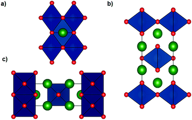
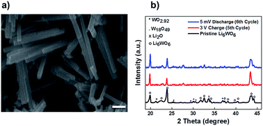
The Li6WO6 crystal structure (viewed from different axes) is shown in Fig. 1. It is an orthorhombic structure with the space group Immm (no. 71), which if more appropriately written as Li3W0.5O3 would indicate a W occupancy of 0.5 in the corner-sharing WO6 octahedra. From the figure, the Li atoms seem unencumbered along the b axis, and so it would appear that Li transportation occurs through the b-channel.Fig. 2a demonstrates the SEM micrograph of Li6WO6 with 1D morphology. The average diameter of nanowires is between 200–500 nm. The XRD patterns of the as-synthesized nanowire sample as well as samples after charge–discharge cycles are shown in Fig. 2b. The diffraction pattern of the as-synthesized sample matches well with the characteristic peaks of Li6WO6 (PDF 00-021-0532). The pristine sample also shows the presence of some unconverted tungsten oxide in reduced form, WO2.92 (PDF 00-030-1387) and W18O49 (PDF 03-065-1291).
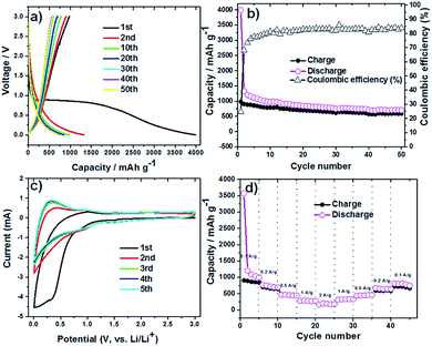
The lithium insertion and extraction cycling behavior is demonstrated in Fig. 3. The charge–discharge capacity curves of the Li6WO6 nanowire anode are shown in Fig. 3a. For the voltage range of 3.0–0.005 V (vs. Li/Li+) using a high current rate of 100 mA g−1, initial discharge and charge capacities of 3986 and 981 mA h g−1 were noted during the first cycle respectively, whereas the discharge capacity in the second cycle was reduced to 1324 mA h g−1. This capacity degradation between the first and second cycle can be mainly attributed to the irreversible decomposition of the electrolyte, which promotes the formation of a surface passivation layer commonly known as a solid electrolyte interphase (SEI).34,35 Thereafter, the electrode exhibits great capacity retention, which indicates good reversibility and cycling performance. Overall, the discharge capacity of the Li6WO6 nanowire electrode remained as high as 705 mA h g−1 even after 50 cycles. The charge–discharge capacities versus cycle number for the Li6WO6 anode electrode in the voltage range of 3.0–0.005 V with a current of 100 mA g−1 are presented in Fig. 3b. The coulombic efficiency was calculated from the charge–discharge curves. The coulombic efficiency of the 50th charge–discharge cycle was found to be ∼85%. The huge enhancement in the coulombic efficiency between the first and 50th cycle indicates a highly reversible lithium insertion and desertion process. However, the low initial coulombic efficiency is attributed to the irreversible capacity loss resulting from the development of a SEI layer. In addition, given that this anode material is new, the low initial coulombic efficiency may have been due to compatibility issues with the binder utilized in the experiment, and so, further investigative work regarding more suitable or compatible binders may be necessary going forward. The cyclic voltammetry (CV) curves of Li6WO6 at a scan rate of 1 mV s−1 between 0.002 and 3 V are shown in Fig. 3c.
In the first cathodic polarization curve, the lithium insertion process can be visualized at around 0.8 V and increases steadily until it reaches 0.002 V. Also, a reduction peak was observed at 0.28 V during the initial cathodic scan that disappeared in the following cathodic cycles, which could indicate some irreversible lithium insertion into the crystal structure and the formation of a SEI that causes irreversible capacity loss between the first and second cycles.32
During the first anodic polarization cycle, the current peak appears at 1 V, indicating a lithium extraction process. For the following cycles, this peak shifts towards lower potentials that further confirms unrecoverable phase transformation due to SEI formation. The reproducible CV curves obtained from the second cycle onwards indicate a reversible Li insertion/extraction process for the Li6WO6 NW anode.
The rate capability of the Li6WO6 nanowire anode is shown in Fig. 3d. When the charging rate was increased stepwise in the sequence of 100, 200, 500, 1000 and 2000 mA g−1, discharge capacities of 999, 691, 448, 268, 174 mA h g−1 were achieved. Afterwards, when the current rate was reduced back to 1000, 500, 200, and 100 mA g−1, stable discharge capacities of 330, 464, 645 and 749 mA h g−1 were obtained. These results indicate that Li6WO6 is an efficient material to use as a high-rate lithium ion battery anode. The highly reversible capacity achieved after cycling at different current rates may be related to the high structural flexibility of the lithium hexaoxotungstate NWs during the charge–discharge volume swing. As a matter of fact, one of the key challenges in the design of efficient anode materials remains the structural integrity of electrode materials over consecutive discharge–recharge cycles.8,36
It was suggested in previous reports that pre-lithiation of tungsten oxide can provide structural stability during charge and discharge cycles.32 To develop a better understanding of the lithium insertion and extraction process and to investigate the phase changes during the galvanostatic charge and discharge cycles, we performed ex situ XRD on our samples after the 5th charge and 6th discharge cycles (Fig. 2b). The presence of excess Li in the form of lithium oxide coming from the material preparation method was largely reduced as can be seen from the reduction in the peak intensity corresponding to Li2O for the charged and discharged sample. We believe that excess lithium oxide was likely extracted in the first discharge cycle. Also, the residual reduced tungsten oxide that was observed in the diffraction pattern of the pristine sample was mostly converted during the lithium insertion and extraction cycles, which was confirmed by the disappearance of some of the corresponding reflections in the XRD patterns. A few unknown reflections appeared in the patterns of the tested sample that could not be matched with any phase and therefore very likely emanated from a secondary reaction at the electrolyte–electrode interface, which is also in accordance with the cyclic voltammetry results that indicate the existence of electrolyte decomposition products. Also, The X-ray diffraction analysis done after the fifth charging cycle indicates that material does not degrade during the charge–discharge process.
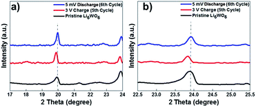
As can be seen from Fig. 4, a shift in peaks toward lower angles was observed, which indicates the lithium insertion process in the lattice of Li6WO6. This kind of peak shift occurs when the lithium intercalation causes a slight increase in the size of the unit cell.37,38
XRD performed after the 6th discharge (lithium extraction) cycle showed that the major peaks were retained at their original position after the discharge process. These results suggest that during the lithiation process, the lattice of Li6WO6 expands, while during delithiation, the guest lithium ions leave the lattice of Li6WO6 without affecting its crystal structure.
The formation of SEI layers can influence the electrode kinetics. When lithium reacts with tungsten forming lithium tungstates, the lithium ion conductivity could be significantly increased and therefore, the reaction resistance can be reduced efficiently.39 We believe that while Li6WO6 may offer increased lithium conductivity, the 1D morphology further helps in reducing the lithium diffusion length, which overall helps to improve the transport properties of the anode.
Conclusions
In summary, Li6WO6 nanowires synthesized via a cost-effective and scalable route were utilized as a negative electrode material for LIBs for the first time. The NWs exhibit a high discharge capacity, excellent rate capability and long cycle life. Granted, the coulombic efficiency is rather low, however, further studies may be required in search of more suitable binders. The a priori presence of Li in the lattice of the Li6WO6 nanowires helped in stabilizing the crystal structure and enhancing lithium diffusion. Lithium intercalation in the nanowires during the insertion stage was evidenced by a slight shift toward lower angles in the diffraction patterns. Overall, the lithium hexaoxotungstate did not undergo degradation during the charge and discharge process and was proven to be an efficient alternative anode material for LIBs by exhibiting phenomenal electrochemical performance and rate capability.Conflicts of interest
The authors declare no conflicts of interest.Acknowledgements
The authors acknowledge partial financial support for this work from the US National Science Foundation (NSF EPSCoR grant 1355438), the National Natural Science Foundation of China (21422303, 21573049, 21872043, 81602643), the National Key R&D Program “nanotechnology” special focus (2016YFA0201600), the Beijing Natural Science Foundation (2142036), the Knowledge Innovation Program, Youth Innovation Promotion Association, the Special Program of “One Belt One Road” of CAS, and support from the CAS-TWAS President's PhD Fellowship Program. The authors also acknowledge partial support from US National Science Foundation (1355438) and the Conn Center for Renewable Energy Research for access to facilities.Notes and references
- J. M. Tarascon and M. Armand, Nature, 2001, 414, 359 CrossRef CAS PubMed.
- P. G. Bruce, B. Scrosati and J. M. Tarascon, Angew. Chem., Int. Ed., 2008, 47, 2930–2946 CrossRef CAS PubMed.
- A. S. Arico, P. Bruce, B. Scrosati, J.-M. Tarascon and W. Van Schalkwijk, in Materials For Sustainable Energy: A Collection of Peer-Reviewed Research and Review Articles from Nature Publishing Group, World Scientific, 2011, pp. 148–159 Search PubMed.
- C. Liu, F. Li, L. P. Ma and H. M. Cheng, Adv. Mater., 2010, 22, E28–E62 CrossRef CAS PubMed.
- F.-H. Du, B. Li, W. Fu, Y.-J. Xiong, K.-X. Wang and J.-S. Chen, Adv. Mater., 2014, 26, 6145–6150 CrossRef CAS PubMed.
- J. T. Vaughey, M. M. Thackeray, A. J. Kahaian, A. N. Jansen and C.-h. Chen, US Pat. No. 6,221,531, 2001.
- Y. Lin, W. Xu, X. Zhang, L. Wang and W. Liu, JOM, 2017, 69, 1503–1508 CrossRef CAS.
- K. Cao, T. Jin, L. Yang and L. Jiao, Mater. Chem. Front., 2017, 1, 2213–2242 RSC.
- R. Kumar, P. K. Gupta, A. Agrawal, R. K. Nagarale and A. Sharma, J. Electrochem. Soc., 2017, 164, A785–A795 CrossRef CAS.
- K. J. Griffith, K. M. Wiaderek, G. Cibin, L. E. Marbella and C. P. Grey, Nature, 2018, 559, 556 CrossRef CAS PubMed.
- M. L. Carreon, A. K. Thapa, J. B. Jasinski and M. K. Sunkara, ECS Electrochem. Lett., 2015, 4, A124–A128 CrossRef CAS.
- R. A. Huggins and W. D. Nix, Ionics, 2000, 6, 57–63 CrossRef CAS.
- K. T. Lee and J. Cho, Nano today, 2011, 6, 28–41 CrossRef CAS.
- C. K. Chan, H. Peng, G. Liu, K. McIlwrath, X. F. Zhang, R. A. Huggins and Y. Cui, in Materials for Sustainable Energy: A Collection of Peer-Reviewed Research and Review Articles from Nature Publishing Group, World Scientific, 2011, pp. 187–191 Search PubMed.
- Y. Liu, Y. Jiao, H. Zhou, X. Yu, F. Qu and X. Wu, Nano-Micro Lett., 2015, 7, 12–16 CrossRef CAS PubMed.
- Y. Wang, Y. Wang, D. Jia, Z. Peng, Y. Xia and G. Zheng, Nano Lett., 2014, 14, 1080–1084 CrossRef CAS PubMed.
- H.-W. Lee, P. Muralidharan, R. Ruffo, C. M. Mari, Y. Cui and D. K. Kim, Nano Lett., 2010, 10, 3852–3856 CrossRef CAS PubMed.
- K. Peng, J. Jie, W. Zhang and S.-T. Lee, Appl. Phys. Lett., 2008, 93, 033105 CrossRef.
- L. Mai, L. Xu, C. Han, X. Xu, Y. Luo, S. Zhao and Y. Zhao, Nano Lett., 2010, 10, 4750–4755 CrossRef CAS PubMed.
- C. K. Chan, X. F. Zhang and Y. Cui, Nano Lett., 2008, 8, 307–309 CrossRef CAS PubMed.
- Y. Wang and G. Cao, Adv. Mater., 2008, 20, 2251–2269 CrossRef CAS.
- W. Li, Y.-X. Yin, S. Xin, W.-G. Song and Y.-G. Guo, Energy Environ. Sci., 2012, 5, 8007–8013 RSC.
- R. Verma, C.-J. Park, R. Kothandaraman and U. Varadaraju, Electrochim. Acta, 2017, 258, 1445–1452 CrossRef CAS.
- T. Q. Nguyen, V. Atla, V. K. Vendra, A. K. Thapa, J. B. Jasinski, T. L. Druffel and M. K. Sunkara, Chem. Eng. Sci., 2016, 154, 20–26 CrossRef CAS.
- A. Nambo, J. He, T. Q. Nguyen, V. Atla, T. Druffel and M. Sunkara, Nano Lett., 2017, 17, 3327–3333 CrossRef CAS PubMed.
- M. Z. Akram, V. Atla, A. Nambo, B. P. Ajayi, J. B. Jasinski, J. He, J. R. Gong and M. Sunkara, Nano Lett., 2018, 18, 4891–4899 CrossRef CAS PubMed.
- M. Zheng, H. Tang, Q. Hu, S. Zheng, L. Li, J. Xu and H. Pang, Adv. Funct. Mater., 2018, 28, 1707500 CrossRef.
- M. Sasidharan, N. Gunawardhana, M. Yoshio and K. Nakashima, Nano Energy, 2012, 1, 503–508 CrossRef CAS.
- H.-W. Shim, I.-S. Cho, K. S. Hong, A.-H. Lim and D.-W. Kim, J. Phys. Chem. C, 2011, 115, 16228–16233 CrossRef CAS.
- J. Zhang, J. Pan, L. Shao, J. Shu, M. Zhou and J. Pan, J. Alloys Compd., 2014, 614, 249–252 CrossRef CAS.
- E. Zhang, Z. Xing, J. Wang, Z. Ju and Y. Qian, RSC Adv., 2012, 2, 6748–6751 RSC.
- P. Li, X. Li, Z. Zhao, M. Wang, T. Fox, Q. Zhang and Y. Zhou, Electrochim. Acta, 2016, 192, 148–157 CrossRef CAS.
- D. Li, H. He, X. Wu and M. Li, J. Alloys Compd., 2016, 682, 759–765 CrossRef CAS.
- M. Winter, J. O. Besenhard, M. E. Spahr and P. Novak, Adv. Mater., 1998, 10, 725–763 CrossRef CAS.
- J. Yang, L. Jiao, Q. Zhao, Q. Wang, H. Gao, Q. Huan, W. Zheng, Y. Wang and H. Yuan, J. Mater. Chem., 2012, 22, 3699–3701 RSC.
- Y. Zhao, X. Li, B. Yan, D. Xiong, D. Li, S. Lawes and X. Sun, Adv. Energy Mater., 2016, 6, 1502175 CrossRef.
- W. Liu, K. Kowal and G. Farrington, J. Electrochem. Soc., 1998, 145, 459–465 CrossRef CAS.
- G. Roberts, E. Cairns and J. Reimer, J. Electrochem. Soc., 2004, 151, A493–A496 CrossRef CAS.
- J. Yokoyama, Y. Furuichi, T. Nakayama, T. Komukai, K. Mori and M. Yamauchi, European Patent Application No. 15783468.0, 2017.
| This journal is © The Royal Society of Chemistry 2019 |


