
 Open Access Article
 This Open Access Article is licensed under a Creative Commons Attribution-Non Commercial 3.0 Unported Licence
Behavior of α, β tubulin in DMSO-containing electrolytes†
Aarat P.
Kalra
*a,
Piyush
Kar
b,
Jordane
Preto
a,
Vahid
Rezania
c,
Aristide
Dogariu
d,
John D.
Lewis
 e,
Jack A.
Tuszynski
ae and
Karthik
Shankar
b
e,
Jack A.
Tuszynski
ae and
Karthik
Shankar
b
aDepartment of Physics, University of Alberta, 11335 Saskatchewan Dr NW, Edmonton, Alberta T6G 2M9, Canada. E-mail: aarat@ualberta.ca
bDepartment of Electrical and Computer Engineering, University of Alberta, 9107–116 St, Edmonton, Alberta T6G 2V4, Canada
cDepartment of Physical Sciences, MacEwan University, Edmonton, Alberta T5J 4S2, Canada
dCREOL, The College of Optics and Photonics, University of Central Florida, Orlando, FL 32816, USA
eDepartment of Oncology, University of Alberta, Edmonton, Alberta T6G 1Z2, Canada
First published on 19th June 2019
Abstract
α, β-tubulin is a cytoskeletal protein that forms cylindrical structures termed microtubules, which are crucial to the cell for a variety of roles. Microtubules are frequently modelled as one-dimensional bionanowires that act as ion transporters in the cell. In this work, we used dynamic light scattering (DLS) to measure the hydrodynamic diameter of tubulin in the presence of a polar aprotic co-solvent. We found that the hydrodynamic diameter increased with increasing DMSO volume fraction, almost doubling at 20% DMSO. To evaluate if this was due to an enlarged solvation shell, we performed reference interaction site model (RISM) simulations and found that the extent of solvation was unchanged. Using fluorescence microscopy, we then showed that tubulin was polymerization competent in the presence of colchicine, and thus inferred the presence of oligomers in the presence of DMSO, which points to its mechanism of action as a microtubule polymerization enhancing agent. Tubulin oligomers are known to form when microtubules depolymerize and are controversially implicated in microtubule polymerization. We show that DLS may be used to monitor early-state microtubule polymerization and is a viable alternative to fluorescence and electron microscopy-based methods. Our findings showing that DMSO causes tubulin oligomerization are thus of critical importance, both for creating bio-inspired nanotechnology and determining its biophysical roles in the cell.
1. Introduction
α, β-tubulin is a globular protein heterodimer that polymerizes to form hollow cylindrical tubes termed microtubules (Fig. 1), which play a variety of roles in the cell, such as generating mechanical forces to separate daughter cells, segregating chromatids during mitosis, forming a network for transport of macromolecules, and maintaining cell shape and rigidity in association with actin filaments and intermediate filaments to form the cytoskeleton.1 Inside the cell, microtubules change their lengths through rapid polymerization/depolymerization cycles of free cytosolic tubulin dimers, a process termed dynamic instability.2,3 Microtubule length-shortening events, termed ‘catastrophes’, involve en masse release of tubulin oligomers into the cytosol.4 Due to the crucial roles they play, tubulin and microtubules are key targets for anti-tumor drugs.5–7 In this context, understanding the factors and mechanisms triggering microtubule formation and catastrophe events are critical. Among several key factors, the cytoplasm may strongly affect tubulin/microtubule diffusion processes and mediate or screen specific interactions within or between tubulin dimers, thus altering microtubule dynamics. To understand the role of the cell environment on microtubule dynamics, aspects such as catastrophes and rescues have been studied and shown to be altered in different solvents. For example, glycerol and polyethylene glycol (PEG) are reported to create an ‘excluded volume’ via macromolecular crowding, drastically lowering association rate constants to reduce the critical concentration for nucleation of microtubules in vitro.8,9 The presence of dimethyl sulfoxide (DMSO) has also been shown to reduce the critical concentration required for microtubule polymerisation by 8 to 10 times.10–12 While the effects of these solvents on microtubule dynamics have been quantified and detailed, the effect on tubulin dimers themselves and their ability to aggregate or polymerize, while hypothesized to alter the solvent structure around tubulin, is not well understood.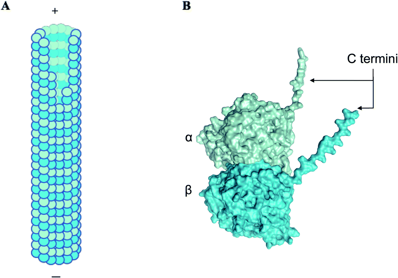 | ||
| Fig. 1 α, β tubulin dimers form long filamentous nanowires termed microtubules. (A) A schematic showing a side view of microtubules, which are hollow cylindrical nanostructures. α, β tubulin dimers stack linearly to form microtubules. (B) A three-dimensional structure of α and β subunits of tubulin, displaying C-terminal ‘tails’, that carry approximately 50% of the net negative charge on the dimer.1 | ||
Due to the negative charge and high dipole moment of the tubulin dimer, counterions have been modelled to condense around microtubules, and to couple with the phonon modes of the microtubule lattice.13,14 The nature of the solvation shell around tubulin, which is crucial in determining protein structure and function,15–18 has been modelled to form a ‘slip layer’ around tubulin, and act as a passage for ionic charge transport.19,20 Characterizing the solvation shell in aqueous media and different solvents is thus of critical importance.
An increasing interest in the use of tubulin for applications in electronics,21,22 nanotechnology23 and biosensors24 elevates the importance of characterising this protein and its assemblies regarding its response to different environments. In this paper, we characterize the response of tubulin dimers to DMSO using Dynamic Light Scattering (DLS) as a first step towards understanding its response to different solvents. Using Reference Site Interaction Model (RISM) simulations, we exclude the possibility of the solvation shell being significantly altered in the presence of DMSO and point towards oligomerization and aggregation as reasons for an increased hydrodynamic diameter. In addition to involvement in microtubule catastrophes, oligomers are also reported to play roles in microtubule elongation and are important to characterize biophysically.25,26 Our research is aimed at studying the biophysical properties of tubulin dimers and oligomers in both aqueous and hostile environments, with a view towards both understanding the biophysics of the cell and eventually developing biologically-inspired nanotechnology.
2. Methods
2.1 Tubulin stock preparation
General tubulin buffer (80 mM PIPES pH 6.9, 2 mM MgCl2, 0.5 mM EGTA; Cytoskeleton Inc; BST01-010) was purchased in powdered form and reconstituted as prescribed by the vendor. This solution was filtered and stored at 4 °C for subsequent use. Lyophilized tubulin stock (5 mg; Cytoskeleton Inc; T-240) was reconstituted using 20 μL of microtubule cushion buffer (general tubulin buffer supplemented with 60% glycerol) added to 180 μL of G-PEM buffer (general tubulin buffer supplemented with 1% GTP). Tubulin solution was snap frozen in liquid nitrogen and stored in 5 μL aliquots at −80 °C.2.2 Measurement of hydrodynamic diameter
DLS was performed using a final concentration of 1.2 μM tubulin and 1.4 μM colchicine in the presence of BRB8. Briefly, 2 μL of colchicine (dissolved in DMSO) was added to 498 μL of BRB80. 11 μL of this solution was added to 0, 7.5, 15, 22.5 and 30 μL of filtered DMSO to form 0, 5, 10, 15 and 20% DMSO (v/v) solutions respectively. 4 μL of tubulin stock was added to this solution and the volume was made up to 150 μL using de-ionized water. The temperature of the system was set to 25 °C using the measurement file. The final solution pH for all cases of DMSO volume fraction was calculated and determined to be approximately 6.9. Once samples were prepared, a Nano-ZS (Malvern Instruments) machine was used for the determination of hydrodynamic diameter. The equipment used for our DLS measurements was a Malvern Nano-ZS located at the National Institute for Nanotechnology (NINT) facility, in Edmonton, Alberta, Canada. The incident laser wavelength was 633 nm, and the instrument automatically set the angle of the detector by accounting for the particle size. Data acquisition was performed by three runs for each sample, and each run entailed multiple/repetitive measurements of particle size, ensuring statistical significance.2.3 Tubulin labelling
Lyophilized tubulin (20 μg; Cytoskeleton Inc, TL-590m) was reconstituted in a 1![[thin space (1/6-em)]](https://www.rsc.org/images/entities/char_2009.gif) :5 labelling ratio with unlabelled tubulin, in 10% glycerol and 1 mM GTP, as recommended. Briefly, 4 μL of G-PEM buffer was added to tubulin powder, followed by 1 μL of microtubule cushion buffer. Tubulin solution was snap frozen using liquid nitrogen and stored in 5 μL aliquots at −80 °C.
:5 labelling ratio with unlabelled tubulin, in 10% glycerol and 1 mM GTP, as recommended. Briefly, 4 μL of G-PEM buffer was added to tubulin powder, followed by 1 μL of microtubule cushion buffer. Tubulin solution was snap frozen using liquid nitrogen and stored in 5 μL aliquots at −80 °C.
2.4 Epifluorescence imaging
Epifluorescence microscopy was performed using a Zeiss Axio Examiner microscope, and a Zeiss 63x Plan-Apochromat objective. 2 μL of solution was pipetted onto silane-prep glass slides (Sigma-Aldrich; S4651) for imaging. Excitation and emission filters of 535 nm and 610 nm, respectively, were used. An exposure of 300 ms and a sensitivity of 100 were kept constant for all images.2.5 Modelling methodology
The 3D RISM method was used to estimate the 3D equilibrium density distribution of solvent around the tubulin dimer.27 3D RISM is based on the Ornstein-Zernike (OZ) equation, which expresses the density distribution in terms of direct and indirect spatial correlation functions. This module is available within the AMBER MD package. Terming gγ(r) the density distribution of atoms of type γ at position r, we introduce the total correlation function hγ(r) as hγ(r) = gγ(r) − 1, where gγ(r) = 1 and hγ(r) = 0 for bulk solvent, i.e., when r → ∞. The total correlation function can in turn be expressed from the direct correlation function leading to the following equation: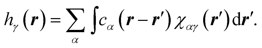 | (1) |
In eqn (1), χαγ(r) stands for the site–site solvent-susceptibility for atom types α and, which was pre-calculated using 1D-RISM by integrating the dielectrically consistent RISM (DRISM) equation coupled with the Kovalenko-Hirata (KH) closure equation. A temperature of 300 K was used for our calculations. 3D-RISM was then applied to compute the 3D density distribution gγ(r) of solvent atoms around our prepared tubulin oligomers.
3. Results and discussion
3.1 Dynamic light scattering
The hydrodynamic diameter of tubulin was measured in BRB8 (Bradley's reconstitution buffer with 8 mM PIPES) as opposed to the standard buffer BRB80 used for microtubule polymerization, since the low ionic strength solution reduces the effect of ionic condensation on the surface of tubulin. The Stokes–Einstein equation, on which size determination using DLS is based, uses temperature, viscosity and refractive index to determine the hydrodynamic diameter of solute particles. Values used for tubulin are shown in Table 1. Our results showed that, consistent with the expected size of tubulin shown previously using X-ray diffraction, DLS and fluorescence correlation spectroscopy (FCS) measurements,28–30 the hydrodynamic diameter of tubulin by number distribution in a BRB8 solution was 7.038 ± 0.0703 nm, (Fig. 2A–C).| DMSO% (v/v) | Parameter xc (nm) | Parameter w (nm) | Reduced Chi-sqr | Adj. R-square | ||
|---|---|---|---|---|---|---|
| Value | Standard error | Value | Standard error | |||
| Number distribution | ||||||
| 0 | 7.038 | 0.070 | 3.306 | 0.176 | 1.425 | 0.957 |
| 5 | 9.459 | 0.068 | 3.922 | 0.170 | 1.432 | 0.971 |
| 10 | 10.784 | 0.064 | 3.883 | 0.157 | 1.518 | 0.975 |
| 15 | 11.641 | 0.069 | 4.220 | 0.169 | 1.449 | 0.976 |
| 20 | 13.155 | 0.077 | 4.773 | 0.190 | 1.467 | 0.976 |
|
||||||
| Volume distribution | ||||||
| 0 | 8.178 | 0.094 | 4.656 | 0.246 | 1.165 | 0.957 |
| 5 | 10.457 | 0.091 | 4.965 | 0.229 | 1.349 | 0.967 |
| 10 | 11.536 | 0.072 | 4.608 | 0.178 | 1.175 | 0.977 |
| 15 | 12.436 | 0.083 | 5.031 | 0.206 | 1.250 | 0.974 |
| 20 | 14.036 | 0.086 | 5.611 | 0.213 | 1.139 | 0.977 |
|
||||||
| Intensity distribution | ||||||
| 0 | 10.527 | 0.194 | 6.593 | 0.524 | 0.170 | 0.912 |
| 5 | 12.105 | 0.091 | 6.010 | 0.230 | 0.049 | 0.9775 |
| 10 | 12.433 | 0.064 | 4.847 | 0.159 | 0.020 | 0.983 |
| 15 | 13.856 | 0.089 | 5.772 | 0.222 | 0.048 | 0.977 |
| 20 | 15.113 | 0.077 | 5.872 | 0.190 | 0.043 | 0.983 |
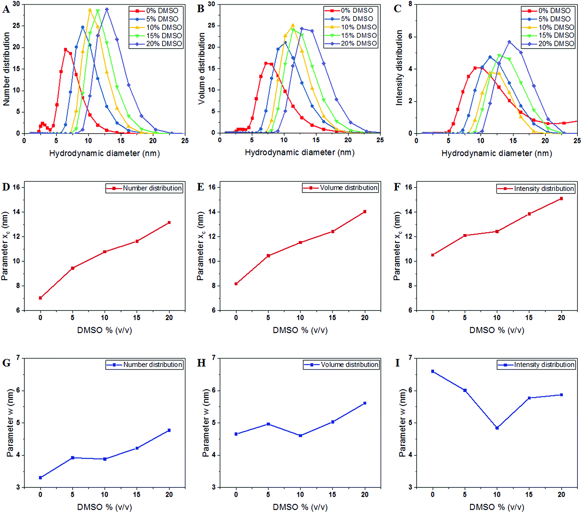 | ||
| Fig. 2 Hydrodynamic size of tubulin dimers measured using DLS. (A–C) Displays the hydrodynamic dimeter of the tubulin dimers determined by number, volume and intensity distributions. (D–F) Displays the peak of the Gaussian fit in the number, volume and intensity distributions, respectively, represented by the parameter xc. (G–I) Displays the FWHM of the Gaussian fit in the intensity plots, represented by parameter w. | ||
The DLS instrument determined the size of the particles using three interpretations: intensity plots showed which size had the highest scattering intensity, the volume plots showed which size occupied the highest volume and the number density plots, which showed which particle sizes were in greatest abundance. After obtaining data from the DLS experiment, we plotted these values and fitted them to a Gaussian as shown in the equation below:
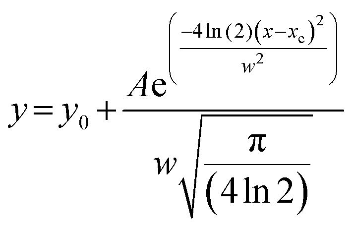 | (2) |
First, to investigate if this increase was a result of changing solvation dynamics as opposed to the formation of oligomers and aggregates, as hypothesized in earlier reports,10 we used computational modelling estimates to evaluate the thickness of the solvation shell.
3.2 Computational modeling estimates of the hydrodynamic diameter
Solvent molecules surrounding proteins in their vicinity may interact strongly with protein structures and may therefore contribute to the value of the hydrodynamic radius RH. For instance, the increase of RH observed in Fig. 3C for increasing DMSO concentration may be partly explained by an increase of the solvation shell thickness, which would lead to an increase in the hydrodynamic radius of tubulin. In order to determine how the solvation shell contributes to the value of RH, molecular structural analysis of tubulin dimers and small oligomers was performed.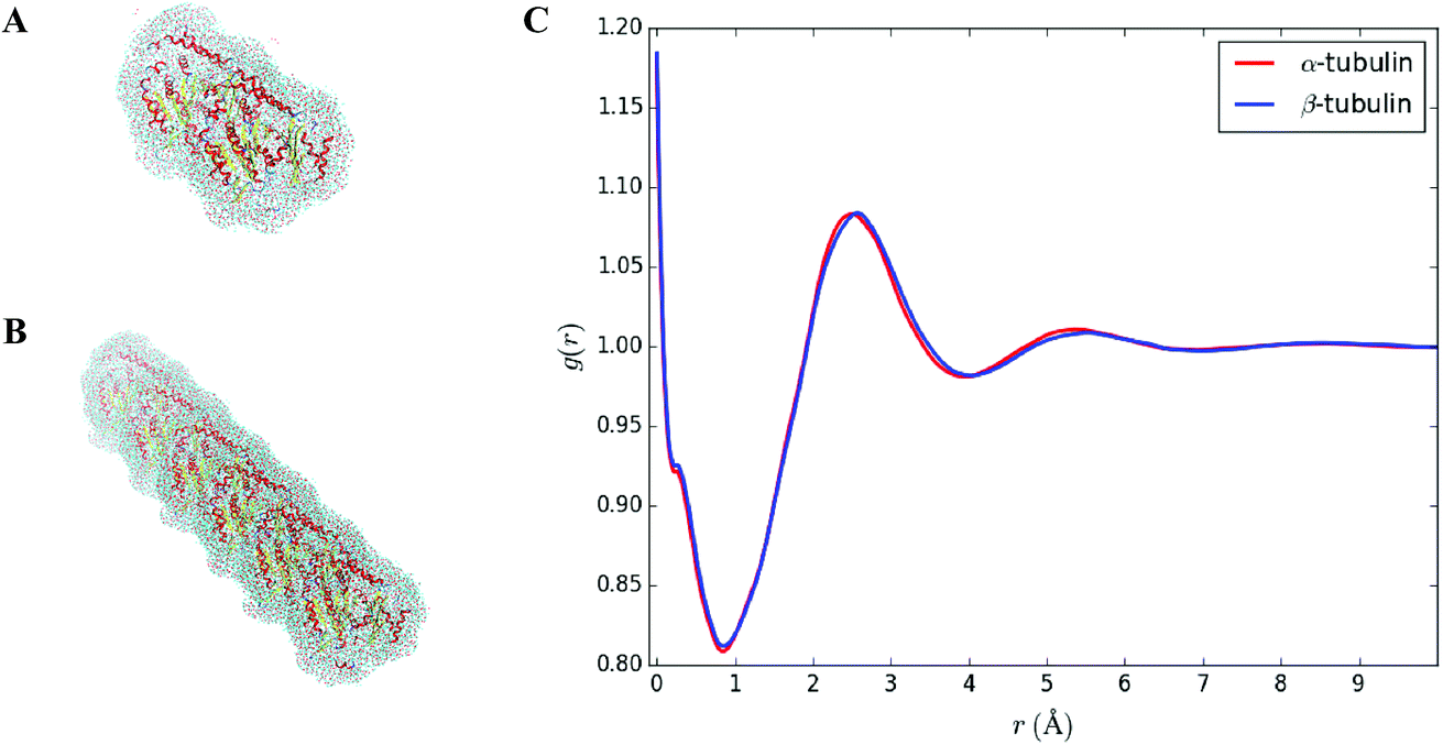 | ||
| Fig. 3 (A) Shape of the solvation shell surrounding a tubulin dimer. Positions of the water molecules were predicted using the placevent.py script. Only water molecules characterized by g(r) > 1, i.e., for which the density is larger than the bulk density, were kept. (B) Shape of the solvation shell surrounding three longitudinally-bound dimers (bottom, 1 × 3 case). (C) Average radial density distribution g(r) of oxygen atoms in pure water for α and β tubulin monomers. g(r) = 1 corresponds to the bulk density. | ||
Structures of tubulin oligomers were obtained by first downloading the Protein Data Bank (PDB) cryo-EM structure 3J6F, which consists of a 3 × 3 lattice of tubulin dimers as part of a GDP-bound microtubule, and by trimming the structure in order to get the desired types of oligomers. Extracted structures include free tubulin dimer (1 × 1), two laterally-bound dimers (2 × 1), two longitudinally-bound dimers (1 × 2), as well as 3 × 1, 2 × 2 and 1 × 3 structures. C-termini together with GTP and GDP cofactors were not considered, as they were assumed to minimally contribute to the hydrodynamic radii of the molecules. Energy minimization was run on each oligomer structure in implicit solvent using the AMBER molecular dynamics (MD).31 The hydrodynamic radius RH of each oligomer in the absence of solvent was computed by first estimating their radius of gyration Rg, which satisfies:
 | (3) |
 is the total mass and rmean are the coordinates of the center of mass of the protein. Next, the hydrodynamic radius of each oligomer was deduced from the well-known relation.32
| Rg = (3/5)1/2RH = 0.77RH, | (4) |
| Oligomer | Vacuum | Water | DMSO (5%) | DMSO (10%) |
|---|---|---|---|---|
| 1 × 1 | 4.52 | 4.8 | 4.8 | 4.8 |
| 1 × 2 | 7.74 | 8.00 | 8.00 | 8.00 |
| 1 × 3 | 11.2 | 11.36 | 11.38 | 11.38 |
| 2 × 1 | 6.02 | 6.28 | 6.28 | 6.28 |
| 3 × 1 | 8.06 | 8.24 | 8.24 | 8.24 |
| 2 × 2 | 8.78 | 8.98 | 8.98 | 8.98 |
In order to investigate how the hydrodynamic diameter changes when solvent is considered, the equilibrium distribution of solvent molecules around each oligomer structure was predicted using the 3D-RISM utility available within the AMBER package. Using 3D-RISM has an advantage over explicit solvation that it does not require periodic boundary conditions, resulting in improved handling of long-range effects. It is worth noting, however, that RISM ignores kinetically-limited phenomena. Simulations were carried out at 0% v/v, 5% v/v, 10% v/v of DMSO/water concentration, consistent with the DLS experiments described in Section 3.1. Note that only water and DMSO molecules were considered for our simulations, i.e., no ions or additional species were added to the solvent. This is because the concentration of ions and other chemical species used in our experimental setup, which includes PIPES, used as a buffer agent, and MgCl2, which is below 1 mM, were assumed to have a negligible influence in the formation of the solvation shell. 3D-RISM requires information about the static dielectric constant ε of the solution as an input. To estimate ε for DMSO/water mixtures, the following equation was applied:33
| ε = [(εDMSO1/3 − εH2O1/3)νDMSO + εH2O1/3]3 | (5) |
To estimate the hydrodynamic diameter, the radius of gyration was first estimated. The following formula was applied:
 | (6) |
 . α indicates the type of solvent atoms considered (e.g., for pure water, α correspond to hydrogens or oxygen). ρα(r) gives the excess solvent mass due to the solute that is discounted by the solvent displaced by the solute, i.e.: ρα(r) = mαcαhα(r), where mα is the mass of atoms of type α, cα is the bulk concentration cα = Nα/V and hα(r) is the total correlation function at r, given as an output of 3D-RISM computations (see material and methods section). Similar to eqn (1), Iprot is the moment of inertia of the protein given by
  . M and rmean are the total mass and the center of mass of the system, respectively, including the solvation shell. Eqn (3) was then used to estimate the hydrodynamic diameter. Values of the hydrodynamic diameter including the solvation shell are provided in the last three columns of Table 2 corresponding to 0% v/v, 5% v/v, 10% v/v of DMSO/water concentration.
An estimate of the hydrodynamic diameter for a single dimer, as given by the first row of Table 2, was found to match with DLS results at 0% DMSO, suggesting no oligomerization or aggregation. However, we noticed from our 3D-RISM simulations that only a small change was observed in the hydrodynamic radius of tubulin oligomers because of the solvent. As shown in Table 2, only an increase of about 1 Å is found when considering the solvation shell. Besides, no significant differences in RH were reported between the pure water case (3rd column of Table 1) and DMSO/water mixtures (4th and 5th columns of Table 2) suggesting that the presence of the solvation shell does not explain the increase of RH observed in DLS experiments when the DMSO concentration is increased. This result appears reasonable assuming a protein will still have the same free energy regardless of solvent thus always influencing the same mass around it.
In order to corroborate values found in Table 1, an average radial distribution of solvent molecules close to the surface of tubulin was computed. Since α and β tubulin monomers are comparable to spherical objects, the density distribution g(r), as provided by our 3D-RISM simulations, was estimated for different values of polar θ ∈ [0, π] and azimuthal angles φ ∈ [0, 2π] starting from the center mass of each monomer. Then, the average distribution g(r) was computed over all the θ and φ values. Fig. 3C shows such an average radial distribution for oxygen atoms in pure water, setting the protein surface to r = 0 Å and the bulk density to g(r) = 1. The hydration shell thickness was taken as the distance between the protein surface and the first minimum of the radial distribution function. This distance corresponds to 0.9 Å, which is close to the 1 Å increase observed in the value of the hydrodynamic radius due to the solvent (see Table 2).
3.3 Epifluorescence microscopy
We used fluorescence microscopy to evaluate if the presence of DMSO was leading to tubulin oligomer formation. We reasoned that if tubulin was undergoing polymerization as opposed to forming amorphous aggregates, it may be possible to image fluorescent microtubules. Fig. 4 shows our results with epi-fluorescence microscopy of labelled-tubulin solutions. For imaging, we used the same concentrations and parameters as our DLS measurement, using 0%, 10% and 20% DMSO. While no polymers existed in the presence 0% and 10% DMSO, microtubules were observed in the presence of 20% DMSO. We thus inferred that tubulin was still polymerization competent, and that the increase in hydrodynamic diameter of tubulin as a function of DMSO volume fraction was due to the presence of oligomers and not amorphous aggregates. Interestingly, microtubule formation in these conditions was contrary to previous expectations for a variety of reasons. Firstly, tubulin concentration was an order of magnitude lower than the critical concentration required for microtubule formation at 37 °C (1.2 μM as compared to ∼22 μM).34 We note that experiments were performed at 25 °C, further reducing the propensity for polymerization. Also, colchicine, a well-known inhibitor of microtubule formation35–37 was added to all solutions (see Materials and methods). All experiments were conducted at lower than standard ionic concentrations (in BRB8 as opposed to BRB80), further inhibiting polymerization, while simultaneously lowering counterionic condensation.38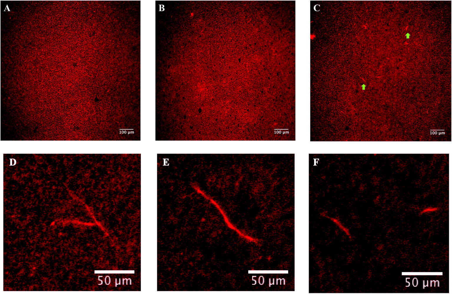 | ||
| Fig. 4 Epi-fluorescence microscopy to show that tubulin remains polymerization competent in the presence of increasing DMSO concentrations. (A–C) Images of 1.2 μM tubulin in 0%, 10% and 20% DMSO and 1.4 μM colchicine in BRB8 solution. The green arrows in C point towards microtubules. (D–F) Magnified images showing microtubule formation. For detailed experimental conditions and epi-fluorescence microscopy setup, see Materials section. | ||
In biochemical assays, DMSO is a commonly used solvent. It is also used as a drug carrier in treatments for dermatological diseases,39 schizophrenia,40 amyloidosis and gastrointestinal disorders.41 The presence of DMSO leads to tumour retardation in mouse breast cancer cells,42 loss of tumorigenic potential in human carcinoma cells,43 alters the biochemical and morphological properties of cancer cells44 and decreases the permeability of breast cancer cells.45 DMSO has also been suggested to act as a stimulator of a tumour suppressor protein HLJ1 in lung cancer cells.46 We thus chose DMSO to study the response of tubulin to DMSO with a view to understand its biophysical effects on the cytoskeleton. Our findings showed that this polar, aprotic solvent did not appreciably alter the solvation shell around tubulin. Further, despite the presence of colchicine, tubulin oligomerization took place. Our approach using DLS to study tubulin polymerization is both novel and consistent with previous reports of DMSO enhancing tubulin polymerization.9,10
4. Conclusion
The hydrodynamic diameter of tubulin was measured using DLS in the presence of increasing volume fractions of DMSO. In aqueous solvent, the hydrodynamic diameter was 7.04 ± 0.07 nm by number distribution, increasing as the volume fraction of DMSO was increased. Interestingly, our simulations using RISM showed that this was not a consequence of increased hydration in the presence of DMSO. Our work points towards the formation of tubulin oligomers in the presence of DMSO.Unlike traditional techniques used to study microtubule dynamics such as fluorescence microscopy, electron microscopy and turbidimetry, DLS quantifies particle size at relatively fast temporal resolutions and requires nominal post-measurement analysis, (such as image reconstruction required for electron microscopy or sub-pixel tracking in fluorescence-based imaging methods). DLS is not hampered by photobleaching and is not affected by the diffraction-limited resolution obtained with a microscope, or other factors that confound imaging such as a high background noise. In the past, limitations with fluorescence-based imaging methods have been typically circumvented by the use of electron microscopy, which requires the sample to be stained prior to imaging, making it susceptible to aggregation and the presence of artifacts. Unlike electron microscopy, which is highly specialized and time consuming, DLS does not require any staining or labelling and is non-destructive, lending itself for use in quantification of various microtubule nucleation parameters.
For the quantification of microtubule dynamics and nucleation, an ideal combination would be the spatial resolution offered by electron microscopy, working in tandem with the temporal resolution offered by fluorescence-based methods such as TIRF (Total Internal Reflection Fluorescence) and CLIC (Convex Lens-Induced Confinement) microscopy. Additionally, DLS can also help understand solvation of tubulin, and explore the validity of the ‘slip-layer’ being present on microtubules and evaluate its response to different environments. DLS is thus a novel technique that straddles both the advantages of fluorescence microscopy and electron microscopy. We envisage its further use in quantification of kinetics of microtubules and other cytoskeletal polymers in the future.
Conflicts of interest
There are no conflicts to declare.Acknowledgements
JAT and KS gratefully acknowledge research funding from NSERC (Canada). APK thanks CMC Microsystems for funding user fee expenses at the UofA nanoFab. This project was partially supported by Novocure, LLC (Haifa, Israel). The authors acknowledge the assistance of Cameron Hough and Dr Mike Xia at Nanotechnology Research Centre (NRC), Edmonton, Canada, for constructive discussions.References
- I. Minoura and E. Muto, Biophys. J., 2006, 90, 3739–3748 CrossRef CAS PubMed.
- L. Cassimeris, N. K. Pryer and E. Salmon, J. Cell Biol., 1988, 107, 2223–2231 CrossRef CAS PubMed.
- J. Howard and A. A. Hyman, Nat. Rev. Mol. Cell Biol., 2009, 10, 569 CrossRef CAS PubMed.
- E.-M. Mandelkow, E. Mandelkow and R. A. Milligan, J. Cell Biol., 1991, 114, 977–991 CrossRef CAS PubMed.
- A. Jordan, J. A. Hadfield, N. J. Lawrence and A. T. McGown, Med. Res. Rev., 1998, 18, 259–296 CrossRef CAS PubMed.
- M. A. Jordan and L. Wilson, Nat. Rev. Cancer, 2004, 4, 253 CrossRef CAS PubMed.
- K. E. Gascoigne and S. S. Taylor, J. Cell Sci., 2009, 122, 2579–2585 CrossRef CAS PubMed.
- M. Wieczorek, S. Chaaban and G. J. Brouhard, Cell. Mol. Bioeng., 2013, 6, 383–392 CrossRef.
- R. A. Keates, Biochem. Biophys. Res. Commun., 1980, 97, 1163–1169 CrossRef CAS PubMed.
- R. H. Himes, P. R. Burton and J. Gaito, J. Biol. Chem., 1977, 252, 6222–6228 CAS.
- J. Robinson and Y. Engelborghs, J. Biol. Chem., 1982, 257, 5367–5371 CAS.
- J. Algaier and R. H. Himes, Biochim. Biophys. Acta, Protein Struct. Mol. Enzymol., 1988, 954, 235–243 CrossRef CAS.
- M. Satarić, D. Ilić, N. Ralević and J. A. Tuszynski, Eur. Biophys. J., 2009, 38, 637–647 CrossRef PubMed.
- D. L. Sekulić, B. M. Satarić, J. A. Tuszynski and M. V. Satarić, Eur. Phys. J. E, 2011, 34, 49 CrossRef PubMed.
- P. Fenimore, H. Frauenfelder, B. McMahon and R. Young, Physica A, 2005, 351, 1–13 CrossRef CAS.
- P. W. Fenimore, H. Frauenfelder, B. H. McMahon and F. G. Parak, Proc. Natl. Acad. Sci. U. S. A., 2002, 99, 16047–16051 CrossRef CAS PubMed.
- S. Ebbinghaus, S. J. Kim, M. Heyden, X. Yu, U. Heugen, M. Gruebele, D. M. Leitner and M. Havenith, Proc. Natl. Acad. Sci. U. S. A., 2007, 104, 20749–20752 CrossRef CAS PubMed.
- M.-C. Bellissent-Funel, A. Hassanali, M. Havenith, R. Henchman, P. Pohl, F. Sterpone, D. van der Spoel, Y. Xu and A. E. Garcia, Chem. Rev., 2016, 116, 7673–7697 CrossRef CAS PubMed.
- J. Pokorný, J. Hašek and F. Jelínek, J. Biol. Phys., 2005, 31, 501–514 CrossRef PubMed.
- J. Pokorný, Bioelectrochemistry, 2004, 63, 321–326 CrossRef PubMed.
- S. Sahu, S. Ghosh, D. Fujita and A. Bandyopadhyay, Sci. Rep., 2014, 4, 7303 CrossRef CAS PubMed.
- I. B. Santelices, D. E. Friesen, C. Bell, C. M. Hough, J. Xiao, A. Kalra, P. Kar, H. Freedman, V. Rezania and J. D. Lewis, Sci. Rep., 2017, 7, 9594 CrossRef PubMed.
- S. Behrens, J. Wu, W. Habicht and E. Unger, Chem. Mater., 2004, 16, 3085–3090 CrossRef CAS.
- E. Haghshenas, T. Madrakian, A. Afkhami and H. S. Nabiabad, Anal. Bioanal. Chem., 2017, 409, 5269–5278 CrossRef CAS PubMed.
- J. W. Kerssemakers, E. L. Munteanu, L. Laan, T. L. Noetzel, M. E. Janson and M. Dogterom, Nature, 2006, 442, 709 CrossRef CAS PubMed.
- J. Mozziconacci, L. Sandblad, M. Wachsmuth, D. Brunner and E. Karsenti, PLoS One, 2008, 3, e3821 CrossRef PubMed.
- G. M. Giambaşu, T. Luchko, D. Herschlag, D. M. York and D. A. Case, Biophys. J., 2014, 106, 883–894 CrossRef PubMed.
- J. M. Andreu and S. N. Timasheff, Proc. Natl. Acad. Sci. U. S. A., 1982, 79, 6753–6756 CrossRef CAS PubMed.
- J. Bordas, E.-M. Mandelkow and E. Mandelkow, J. Mol. Biol., 1983, 164, 89–135 CrossRef CAS PubMed.
- T. Krouglova, J. Vercammen and Y. Engelborghs, Biophys. J., 2004, 87, 2635–2646 CrossRef CAS PubMed.
- D. A. Pearlman, D. A. Case, J. W. Caldwell, W. S. Ross, T. E. Cheatham III, S. DeBolt, D. Ferguson, G. Seibel and P. Kollman, Comput. Phys. Commun., 1995, 91, 1–41 CrossRef CAS.
- D.-M. Smilgies and E. Folta-Stogniew, J. Appl. Crystallogr., 2015, 48, 1604–1606 CrossRef CAS PubMed.
- H. Looyenga, Physica, 1965, 31, 401–406 CrossRef CAS.
- M. Wieczorek, S. Bechstedt, S. Chaaban and G. J. Brouhard, Nat. Cell Biol., 2015, 17, 907 CrossRef CAS PubMed.
- R. L. Margolis and L. Wilson, Proc. Natl. Acad. Sci. U. S. A., 1977, 74, 3466–3470 CrossRef CAS PubMed.
- J. Olmsted and G. Borisy, Biochemistry, 1973, 12, 4282–4289 CrossRef CAS PubMed.
- L. Wilson, Life Sci., 1975, 17, 303–309 CrossRef CAS PubMed.
- J. Olmsted and G. Borisy, Biochemistry, 1975, 14, 2996–3005 CrossRef CAS PubMed.
- K. Capriotti and J. A. Capriotti, J. Clin. Aesthet. Dermatol., 2012, 5, 24 Search PubMed.
- R. Smith, Med. Hypotheses, 1992, 39, 248–257 CrossRef CAS PubMed.
- A. S. Salim, Transl. Res., 1992, 119, 702–709 CAS.
- R. Deng, S.-m. Wang, T. Yin, T.-h. Ye, G.-b. Shen, L. Li, J.-y. Zhao, Y.-x. Sang, X.-g. Duan and Y.-q. Wei, J. Breast Cancer, 2014, 17, 25–32 CrossRef PubMed.
- I. Goto, Y. Yamamoto-Yamaguchi and Y. Honma, Br. J. Cancer, 1996, 74, 546 CrossRef CAS PubMed.
- Y. S. Kim, D. Tsao, B. Siddiqui, J. S. Whitehead, P. Arnstein, J. Bennett and J. Hicks, Cancer, 1980, 45, 1185–1192 CrossRef CAS PubMed.
- C. C. Cyran, B. Sennino, B. Chaopathomkul, Y. Fu, V. Rogut, D. M. Shames, M. F. Wendland, D. M. McDonald and R. C. Brasch, Invest. Radiol., 2008, 43, 298 CrossRef CAS PubMed.
- F. Wang, L. He, W.-Q. Dai, Y.-P. Xu, D. Wu, C.-L. Lin, S.-M. Wu, P. Cheng, Y. Zhang and M. Shen, PLoS One, 2012, 7, e50638 CrossRef CAS PubMed.
Footnote |
| † Electronic supplementary information (ESI) available. See DOI: 10.1039/c9na00035f |
| This journal is © The Royal Society of Chemistry 2019 |