 Open Access Article
Tunable index metamaterials made by bottom-up approaches†
Mayte
Gómez-Castaño
ab,
Hanbin
Zheng
a,
Juan Luis
García-Pomar
 b,
Renaud
Vallée
 a,
Agustín
Mihi
 *b and
Serge
Ravaine
 *a
*a
aCentre de Recherche Paul Pascal, CNRS, UMR 5031, University of Bordeaux, F-33600 Pessac, France. E-mail: ravaine@crpp-bordeaux.cnrs.fr
bInstitute of Materials Science of Barcelona, CSIC, Campus de la UAB, 08193 Bellaterra, Spain. E-mail: amihi@icmab.es
First published on 5th December 2018
Abstract
Despite the exciting optical properties metamaterials exhibit, their implementation in technology is being hampered nowadays by the inherent losses of their metal constituents and the expensive and low-throughput procedures used. As an alternative, we present a new design of double fishnet metamaterials that can be easily realized combining two inexpensive and up-scalable techniques: nanosphere lithography and metallic electrodeposition. A monolayer of polystyrene spheres is used as a template for the infiltration of two symmetric gold layers separated by an air gap. The effective refractive index of the metamaterial can be easily tuned by the appropriate choice of the diameter of the spheres and the gap width between the metallic layers, varying its value from positive to negative. The good agreement between optical measurements and finite-difference time-domain simulations confirms the success of our process. Fishnet metamaterials with refractive index going from 1.5 until −1.0 in the near infrared range are demonstrated and the key parameters for these architectures provided.
Introduction
Metamaterials have attracted a great deal of attention over the recent years because of the exotic electromagnetic phenomena that they can present. Their artificially engineered structure enables the appearance of novel exciting properties not observed in naturally occurring substances such as negative or zero index of refraction. Besides the challenging physics explaining their optical characteristics, negative-index metamaterials (NIMs)1 stand out for their potential application as super lenses, with an image resolution beyond the diffraction limit.2 This negative refractive index is achieved by engineering the values of the complex electric permittivity ε = ε′ + iε′′ and magnetic permeability μ = μ′ + iμ′′ in the same spectral region. Depine et al.3 demonstrated that the necessary condition for such behavior implies that ε′μ′′ + μ′ε′′ < 0. Based on this requirement, NIMs can be classified into two groups: double-negative, that present simultaneously ε′ < 0 and μ′ < 0, and single-negative, where negative refraction is still reachable with only one of these parameters being negative.A very stimulating phenomenon is obtained when ε′ and μ′ approach values close to zero, leading to the so-called near-zero-index metamaterials (NZIMs).4 The interest in these structures relies on their intrinsic characteristics of small phase variation as light propagates and the possibility of tailoring the outgoing radiation pattern. As a result, an extensive variety of applications have been proposed, including the energy tunneling effect,5 highly directive radiation6 or cloaking.7
Nowadays diverse designs are being studied and developed for the realization of such properties based on metallic,8 all-dielectric,9 semiconductor10 or graphene11 metamaterials. Among the classic metal–dielectric structures, a widely studied geometry to achieve unusual refractive index values in the visible and near-infrared (NIR) ranges is the fishnet design. It consists of a 2D array of dielectric holes penetrating a multilayered structure of metallic and dielectric films. This configuration is known to allow an independent control of the permittivity and the permeability at a specific wavelength.12 In particular, the electric response is governed by the cutoff frequency of the hole waveguide whereas the magnetic behavior is associated with the excitation of the so-called gap surface plasmon polariton modes in the dielectric cavities.13
Since the first experimental demonstration in 2005,14 different experimental and theoretical designs of fishnet NIMs have been published. While the highest figures of merit (FOM = |Re (n)/Im (n)|) are found for structures operating around 1.5–2.5 μm,15–21 NIMs working at the visible range and its vicinity have also been successfully studied and fabricated, showing FOMs that range from 0.3 to 1.3.22–26 The strong metal losses at these wavelengths have been counteracted by incorporating active optical media into these structures.27,28 Similarly, fishnet NZIMs can be found operating at both the near-infrared region and the visible spectrum.16,29 The major drawback for the large area production of metamaterials nowadays is their cost since the commonly used lithographic techniques based on electron beam,22 laser interferometry20 or focused ion beam30 imply expensive and low-throughput processes. Even when using nanoimprinting or nanosphere lithography (NSL), most of the procedures still involve costly top-down deposition equipment such as electron beam evaporation18 or sputtering.31 A promising alternative is the combination of NSL with electrodeposition as previously reported.32 However, first attempts to fabricate the required architecture with such techniques suffered from lateral misalignment of the holes in the metallic layers, thereby inhibiting the achievement of a large negative index.33
In this work, we present a new double-fishnet design based on such a combination of NSL and electrodeposition, two well-known scalable and low-cost techniques. We are truly able to control several experimental parameters such as the diameter of the spheres and the space between the metallic layers, thus enabling the effective refractive index tuning from positive to negative and zero values in the NIR range. We provide the key parameters controlling the optical response of these metamaterials achieved by an entirely bottom-up fabrication route.
Results and discussion
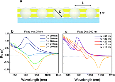
The geometry proposed in this work (Fig. 1a) consists of two gold layers separated by an air gap and symmetrically perforated by a 2D hexagonal array of polystyrene (PS) spheres on top of a glass substrate. Numerical simulations were performed to study the evolution of the effective refractive index n of the structure when tuning its two main parameters: the diameter (D) of the beads and the gap width (w) between two 50 nm thick gold layers for a given lattice parameter (L), i.e., center-to-center distance, of 480 nm. The real part of n for different sphere diameters and widths of gap is plotted in Fig. 1b and c, respectively. As can be observed, by separately tuning one of the two parameters, the value of the refractive index changes, moving from positive to negative and redshifting when decreasing either D or w in the simulated ranges.In particular, small decreases in w produce large redshifts of the operating wavelength of the structure, while reductions in D primarily result in lower values of n. Consequently, the sizes of D and w act as turning knobs that enable us to achieve metamaterials featuring positive, zero and negative refractive indices.
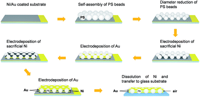
The entirely bottom-up fabrication process of the double-fishnet materials is summarized in Fig. 2. First, a close-packed monolayer of 480 nm PS beads is self-assembled from water on a nickel-plated conductive substrate.34 Polystyrene spheres (n = 1.59) are used for the monolayer assembly because of their low size dispersion and the high quality of the monolayer assembly that can be attained. Similar results are also possible with other polymeric microspheres available (polyamide or polyethylene) with a slight blue-shift of the optical features attributed to the smaller refractive indices of these materials (see Section 1 of the ESI†). Once on the substrate, the size of the particles is reduced by oxygen plasma etching while controlling the time of treatment to obtain non-close-packed monolayers of different diameters (ESI Fig. S2†). The resulting array is then used as a template for metallic electrodeposition, where the metal layers grow upwards starting from the conductive substrate.35,36 Sacrificial nickel layers are deposited as supports for gold layers and allow posterior removal and transfer of the structure. In this way, subsequent electrodeposition of nickel, gold, nickel and gold through the PS template produced two perfectly aligned 50 nm thick gold layers, symmetrically placed with respect to the equatorial plane of the PS beads and separated by a variable sacrificial Ni spacer (ESI Fig. S3†). Finally, the structure is immersed in nitric acid (HNO3) to dissolve the Ni parts. Once detached from the substrate, the sample is scooped and transferred to a transparent glass slide.
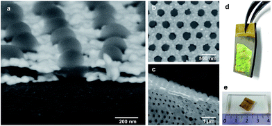
The double fishnet metamaterial structure obtained after Ni removal is depicted in Fig. 3a, where one can easily recognize the two gold layers separated by an air gap surrounding the particles. The hexagonally well-arranged PS beads are still present in the sample after the HNO3 treatment as shown in Fig. 3b. This approach enables the fabrication of free-standing membranes, once detached from the substrate (Fig. 3c), illustrating the flexibility and potential adaptability of these double-fishnet materials to different surfaces and substrates fabricated over centimeter-size areas (Fig. 3d and e).
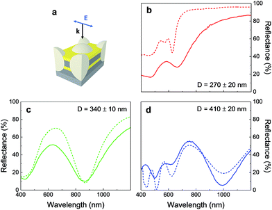
In order to ensure the most reliable reproduction of the optical properties of the structures, optical characterization was performed throughout each fabrication stage and compared to the predictions obtained by finite-difference time-domain (FDTD) simulations as control steps. Measured and simulated reflectance spectra of three samples with different values of D were recorded just after the same multilayer deposition (Fig. 4b–d), which consisted of a first supporting Ni layer, two 50 ± 9 nm thick Au layers and a 70 ± 8 nm thick Ni spacer placed on a nickel substrate as depicted in Fig. 4a.
A very good correlation between the experimental and the numerically simulated curves can be appreciated, confirming the successful deposition through the colloidal template. The slight discrepancies between both spectra are justified in Section 3 of the ESI.† A redshift of the main valley in the reflectance spectra is observed as D values become larger, being located at around 660, 870 and 990 nm for D equal to 270, 340 and 410 nm, respectively, which confirms the dependence of the optical response of the structure on the diameter. Further insight into this resonance is given in ESI Fig. S5,† where the electromagnetic spatial profiles at the nickel middle plane are presented for the numerically obtained wavelength of resonance shown in Fig. 4b. There it can be seen that both the electric and magnetic fields stay confined inside the particles in the presence of nickel around them. This means that the periodic system confines the radiation at larger wavelengths as D increases, modifying the optical response as observed.
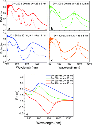
Following the nickel removal and transfer to glass substrates, the double-fishnet structures were optically characterized in reflectance and transmission modes. Fig. 5 shows the extinction spectra (1-R–T, where R denotes the reflection and T the transmission) obtained from double fishnet metamaterials featuring different combinations of D and w, revealing a main extinction peak that shifts towards the NIR region as a function of these two parameters. Close inspection of the extinction spectra enables us to identify the role played by the diameter of the spheres and the gap width. Fig. 5a and b illustrate how for a fixed gap width of 25 nm, the resonance blue-shifts from 920 to 890 nm when increasing the diameter of the beads. In contrast, when keeping D = 300 nm constant, decreasing the gap from 25 to 15 nm redshifts the features towards 970 nm (Fig. 5b and c). This trend is also confirmed when keeping the same gap width of 15 nm but increasing the diameter to 350 nm, which blue-shifts the resonance to 920 nm (Fig. 5c and d).
Close inspection of the samples by SEM and the simulated curves pointed out a slight decrease in the particle size as well as in the space between the gold layers after the immersion in HNO3. The broadening of the measured spectra with respect to the numerical calculations is attributed to some fluctuations of the parameters D and w over 100 μm length scales after Ni dissolution, which are quantified in the form of error ranges. Nevertheless, a fairly good agreement between numerical and experimental results can be observed.
The effective refractive indices corresponding to each metamaterial film were extracted from the simulated transmitted and reflected electromagnetic fields following previous reports37,38 and taking into account the bianisotropy of the structures caused by the presence of the substrate39,40 (see ESI Section 5 for details†). The real parts of the refractive index retrieved from the different metamaterials are summarized in Fig. 5e. The values vary from positive to negative depending on D and w, both parameters acting as turning knobs for the optical properties of the metamaterials. In this context, the sample with the largest diameter (D = 350 nm) exhibits a positive n over the whole wavelength range of interest despite its small gap thickness of 15 nm. This value of the refractive index can approach zero for the double fishnet structure with D = 300 nm and w = 25 nm (n = 0.5 at 855 nm), and for the one with D = 300 nm and w = 15 nm (n = −0.16 around 970 nm). Negative refractive indices are also within reach for fishnets with the appropriate structural parameters. The metamaterial with D = 200 nm and gap = 25 nm exhibits a minimum value of −1.0 at 945 nm, being well below zero over a broad spectral range of 100 nm width. To illustrate the behavior of light through this metamaterial, an ideal prism composed of several layers of the basic structure has been numerically modelled. ESI Fig. S9† shows how the light front propagates with a negative refraction angle at λ = 945 nm. Two movies showing negative phase propagation through the beads and negative refraction of the impinging wave are also provided in the ESI.† The angle dependence of the structure has been well studied, revealing a redshift of the extinction resonance as the angle of incidence increases (ESI Fig. S10†), in line with previous studies.13 This result suggests that our structure could operate at different wavelengths depending on the incident angle.
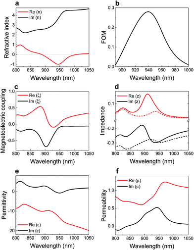
The major effective properties for the sample exhibiting a negative refractive index of −1.0 are presented in Fig. 6. The reasonably high imaginary part of the effective index (Fig. 6a) likely originates from the strong energy dissipation in the gold layers when light travels through the metamaterial. Consequently, its FOM gets a maximum value of around 0.3. Additionally, the substrate under the fishnet structure unfavorably affects both the minimum Re (n) and the FOM when compared with the free-standing case (Fig. S8 of the ESI†), in agreement with previous studies.40 The break of symmetry coming from the substrate is revealed by a non-zero magnetoelectric coupling ξ at the region of operation (Fig. 6c). As a consequence, the electromagnetic impedance z adopts different values depending on the direction of propagation of the incoming light. Fig. 6d shows the real and imaginary parts of z for light coming from the air (solid curves) and from the substrate side (dashed curves). The real and imaginary parts of the effective permittivity and permeability are shown in Fig. 6e and f, respectively. We can observe that whereas ε′ has a negative value over the whole plotted range, μ′ remains positive. We have therefore realized a single-NIM working in the near-infrared region. Replacing our structures by a slab possessing these effective properties, the optical properties shown in Fig. 5a–d have been successfully reproduced making use of the Fresnel equations (see Section 8 of the ESI†), which confirms the validity of our retrieval. The losses due to the inherent metallic absorption could be compensated by including a gain optical medium within the gap,27,32 making feasible the imaging beyond the diffraction limit with bottom-up approaches.
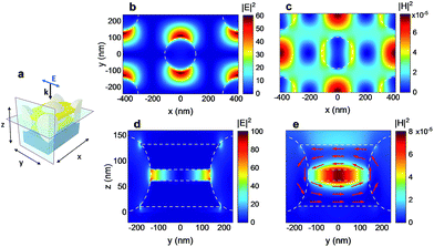
In order to understand the correlation between the retrieved effective properties and the resonance at this region (Fig. 5a), the electromagnetic spatial distribution for the maximum of extinction (λ = 920 nm) is calculated for the two planes depicted in Fig. 7a. At the air middle plane in between the gold layers, the electric field presents a polarization dependent dipole around the particles (Fig. 7b), in contrast with what was found in the presence of nickel (ESI Fig. S5†). Equivalently, in this case a new magnetic resonance is found in both x and y directions at the center position between the PS spheres (Fig. 7c). This structure behaves as an inductor and capacitor resonator where antisymmetric currents are created in the metallic strips along the y direction between the spheres as illustrated with red arrows in Fig. 7e. These currents are induced by the propagation at the air–gold internal interfaces of the so-called gap surface plasmon polaritons (SPPs), which occur when the two metallic layers are close enough so their evanescent fields overlap.41,42 The electric field pointing at opposite directions generates a magnetic dipole parallel to the x direction and confined in the dielectric spacer as can be observed in Fig. 7e.43 Consequently, the magnetic resonance, and therefore the negative index, strongly depends on the gap width, disappearing for the limiting case when the metallic separation reaches zero (see Section 9 of the ESI†). On the other hand, the electric permittivity response of these structures is dominated by the cutoff wavelength of the hole waveguide and gives us the transition between positive and negative values of the real part of the effective permittivity.13 From an analog point of view, for the studied ranges of values, when the diameter of the spheres decreases, the fill factor of the gold layers increases and gives rise to larger negative values of the permittivity and, consequently, of the refractive index (Fig. 1b). This trend is reversed for smaller diameters, for which light does not effectively couple to the periodic structure (see Section 9 of the ESI for further details†). These are the reasons why the dielectric gap between the gold layers and the diameter of the spheres can be considered as the main keys for achieving a negative index metamaterial.
Conclusions
A new design of double fishnet metamaterials has been fabricated by nanosphere lithography and electrochemical deposition over centimeter-size surfaces. The obtained structures exhibited extinction resonances in the NIR that were tunable as a function of the diameter of the particles and the air gap width between the metallic layers. The good agreement between the optical measurements and the simulated spectra throughout the entire fabrication process attests the good control over the fishnet structures as well as the reliability of the calculations. From the latter, the effective optical properties of the structures were retrieved, demonstrating that we were experimentally able to tailor the refractive index from positive to negative values. The minimum achieved corresponded to a single-NIM with n = −1.0 and FOM ≈ 0.3 around 940 nm, working over a 100 nm wide spectral band. Electromagnetic field distributions confirmed that the nature of this behavior is related to the excitation of a magnetic resonance within the dielectric gap, in agreement with previous studies. We have therefore developed an effective route for low-cost and large-scale implementation of NIR negative index metamaterials.Experimental
Samples fabrication
Monodisperse polystyrene (PS) beads with a diameter equal to 480 ± 7 nm were synthesized by emulsion polymerization according to a reported procedure.44 Close-packed monolayers of PS spheres were formed by direct assembly at the air–water interface34 and transferred onto nickel-plated gold-coated glass slides previously cleaned by UV treatment. After a sintering step of 1 hour at 90 °C to fix the position of the beads, the diameter was reduced by oxygen plasma using a Plasma Etch PE100. The working conditions were 10 sccm flow of O2, a plasma power of 80 W and a cooling temperature of 15 °C. Etching times of 90, 120 and 150 s were used to form multiple non-close packed monolayers. After a short rinsing step, the samples were sintered for 15 min at 102 °C to improve adhesion of the beads onto the substrate before electrodeposition. Subsequently, the templates were used as working electrodes in a typical three-electrode cell using a 3 mm thick glassy carbon plate from Alfa Aesar as the counter electrode and a Ag/AgCl electrode from Alvatek as the reference electrode. A cyanide-free gold plating bath purchased from Metalor (ECF60) and nickel plating solution purchased from Alfa Aesar (bright-finish) were used as electrolytes. The cell was kept in a water bath set at 25 °C. Nickel and gold electrodeposition steps were carried out under potentiostatic mode at constant potentials of −0.9 and −0.7 V, respectively. The intensity of the faradaic current generated from the ion reduction was measured using an Autolab PGSTAT 20 potentiostat (EcoChemie) monitored by the GPES 4.9 software. The control of the electrodeposition time allowed us to finely adjust the thickness of the metallic layers. The dissolution of the nickel layers was done by immersing the samples into 10% vol diluted nitric acid (Sigma Aldrich) at room temperature for 1 hour. Once the free-standing samples were detached from the initial substrate, they were carefully scooped on new glass slides.Samples characterization
SEM images were obtained using a Quanta FEI 200 FEG-ESEM microscope operating at 10 kV, and secondary and backscattered electrons were detected. The errors of the metallic layers and the particle sizes correspond to the standard deviation of their mean values obtained from the image analysis. The vis-NIR spectra prior to the nickel dissolution were recorded at normal incidence using a CRAIC 2020 microspectrophotometer. Reflected light was collected through a 10× objective working with a 50 × 50 μm spatial aperture. The vis-NIR reflectance and transmission spectra after nickel dissolution were measured with a Bruker Vertex 70 FTIR spectrophotometer attached to a Bruker Hyperion optical microscope. A 4× objective with a spot size of 400 × 400 μm was employed. A silver mirror exhibiting a ≥96% reflectivity was used as the reference for every reflectance measurement. The experimental optical properties shown are an average of several measured points on each sample.Numerical simulations
The optical response of the structures was modelled by finite-difference time-domain methods using Lumerical FDTD-solutions. The dispersion models of Au and Ni were taken from Johnson and Christy45 and Palik,46 respectively, whereas the polystyrene spheres and the glass substrate were considered to have constant indices of nPS = 1.59 and nsub = 1.56. The errors of the fitted gap widths were obtained from simulations whose resonance was within the full width at half maximum (FWHM) of each experimental peak. The effective properties were extracted applying the homogenization method for bianisotropic metamaterials following previous procedures (see ESI Section 5†).37–39Conflicts of interest
There are no conflicts to declare.Acknowledgements
This work was supported by the French National Research Agency (ANR) as part of the Initiative for Excellence IdEx Bordeaux program (ANR-10-IDEX-03-02) and the Spanish Ministry of Economy, Industry and Competitiveness (MINECO) through grant MAT2016-79053-P and through grant SEV-2015-0496 in the framework of the Spanish Severo Ochoa Centre of Excellence program. This project received funding from the European Research Council (ERC) under the European Union's Horizon 2020 research and innovation program (grant no. 637116, ENLIGHTENMENT).Notes and references
- V. G. Veselago, Phys.-Usp., 1968, 10, 509–514 CrossRef.
- J. B. Pendry, Phys. Rev. Lett., 2000, 85, 3966–3969 CrossRef CAS PubMed.
- R. A. Depine and A. Lakhtakia, Microw. Opt. Technol. Lett., 2004, 41, 315–316 CrossRef.
- R. W. Ziolkowski, Phys. Rev. E: Stat., Nonlinear, Soft Matter Phys., 2004, 70, 046608 CrossRef PubMed.
- M. Silveirinha and N. Engheta, Phys. Rev. Lett., 2006, 97, 157403 CrossRef PubMed.
- S. Enoch, G. Tayeb, P. Sabouroux, N. Guerin and P. Vincent, Phys. Rev. Lett., 2002, 89, 213902 CrossRef PubMed.
- J. Hao, W. Yan and M. Qiu, Appl. Phys. Lett., 2010, 96, 101109 CrossRef.
- G. Yoon, I. Kim and J. Rho, Microelectron. Eng., 2016, 163, 7–20 CrossRef CAS.
- S. Jahani and Z. Jacob, Nat. Nanotechnol., 2016, 11, 23–36 CrossRef CAS PubMed.
- M. R. Shcherbakov, S. Liu, V. V. Zubyuk, A. Vaskin, P. P. Vabishchevich, G. Keeler, T. Pertsch, T. V. Dolgova, I. Staude, I. Brener and A. A. Fedyanin, Nat. Commun., 2017, 8, 17 CrossRef PubMed.
- X. He, P. Gao and W. Shi, Nanoscale, 2016, 8, 10388–10397 RSC.
- J. Valentine, S. Zhang, T. Zentgraf and X. Zhang, Proc. IEEE, 2011, 99, 1682–1690 Search PubMed.
- A. Mary, S. G. Rodrigo, F. J. Garcia-Vidal and L. Martin-Moreno, Phys. Rev. Lett., 2008, 101, 103902 CrossRef CAS PubMed.
- S. Zhang, W. Fan, N. C. Panoiu, K. J. Malloy, R. M. Osgood and S. R. J. Brueck, Phys. Rev. Lett., 2005, 95, 137404 CrossRef PubMed.
- G. Dolling, C. Enkrich, M. Wegener, C. M. Soukoulis and S. Linden, Opt. Lett., 2006, 31, 1800–1802 CrossRef CAS PubMed.
- J. Valentine, S. Zhang, T. Zentgraf, E. Ulin-Avila, D. A. Genov, G. Bartal and X. Zhang, Nature, 2008, 455, 376–380 CrossRef CAS PubMed.
- D. Chanda, K. Shigeta, S. Gupta, T. Cain, A. Carlson, A. Mihi, A. J. Baca, G. R. Bogart, P. Braun and J. A. Rogers, Nat. Nanotechnol., 2011, 6, 402–407 CrossRef CAS PubMed.
- L. Gao, K. Shigeta, A. Vazquez-Guardado, C. J. Progler, G. R. Bogart, J. A. Rogers and D. Chanda, ACS Nano, 2014, 8, 5535–5542 CrossRef CAS PubMed.
- G. J. Sharp, S. I. Khan, A. Z. Khokhar, R. M. de la Rue and N. P. Johnson, Mater. Res. Express, 2014, 1, 045802 CrossRef.
- Y. Zhou, X. Y. Chen, Y. H. Fu, G. Vienne, A. I. Kuznetsov and B. Lukyanchuk, Appl. Phys. Lett., 2013, 103, 123116 CrossRef.
- T. Cao, C. Wei and M. J. Cryan, J. Opt. Soc. Am. B, 2015, 32, 108–113 CrossRef CAS.
- S. Xiao, U. K. Chettiar, A. V Kildishev, V. P. Drachev and V. M. Shalaev, Opt. Lett., 2009, 34, 3478–3480 CrossRef CAS PubMed.
- Y. Liang, Z. Yu, N. Ruan, Q. Sun and T. Xu, Opt. Lett., 2017, 42, 3239–3242 CrossRef PubMed.
- M. Choi, J. Choe, B. Kang and C. Choi, Curr. Appl. Phys., 2013, 13, 1723–1727 CrossRef.
- U. K. Chettiar, A. V. Kildishev, H.-K. Yuan, W. Cai, S. Xiao, V. P. Drachev and V. M. Shalaev, Opt. Lett., 2007, 32, 1671–1673 CrossRef PubMed.
- S. Zhou, S. Townsend, Y. M. Xie, X. Huang, J. Shen and Q. Li, Opt. Lett., 2014, 39, 2415–2418 CrossRef PubMed.
- S. Xiao, V. P. Drachev, A. V Kildishev, X. Ni, U. K. Chettiar, H. Yuan and V. M. Shalaev, Nature, 2010, 466, 735–740 CrossRef CAS PubMed.
- S. Wuestner, A. Pusch, K. L. Tsakmakidis, J. M. Hamm and O. Hess, Phys. Rev. Lett., 2010, 105, 127401 CrossRef PubMed.
- T. Cao, Y. Zou, A. M. Adawi and M. J. Cryan, Opt. Express, 2014, 22, 22699 CrossRef PubMed.
- A. Rottler, M. Harland, M. Bröll, S. Schwaiger, D. Stickler, A. Stemmann, C. Heyn, D. Heitmann and S. Mendach, Appl. Phys. Lett., 2012, 100, 151104 CrossRef.
- K. Lodewijks, N. Verellen, W. Van Roy, G. Borghs and P. Van Dorpe, Appl. Phys. Lett., 2011, 98, 091101 CrossRef.
- S. Li, B. Gong, D. Cao, Z. Pan, C. Luo and X. Zhao, Appl. Phys. Lett., 2013, 103, 181910 CrossRef.
- B. Gong, X. Zhao, Z. Pan, S. Li, X. Wang, Y. Zhao and C. Luo, Sci. Rep., 2014, 4, 4713 CrossRef PubMed.
- N. Vogel, S. Goerres, K. Landfester and C. K. Weiss, Macromol. Chem. Phys., 2011, 212, 1719–1734 CrossRef CAS.
- M. Heim, S. Reculusa, S. Ravaine and A. Kuhn, Adv. Funct. Mater., 2012, 22, 538–545 CrossRef CAS.
- H. Zheng, R. Vallée, I. Ly, R. M. Almeida, T. Rivera and S. Ravaine, J. Phys. Chem. C, 2016, 120, 1178–1185 CrossRef CAS.
- D. R. Smith, D. C. Vier, T. Koschny and C. M. Soukoulis, Phys. Rev. E: Stat., Nonlinear, Soft Matter Phys., 2005, 71, 036617 CrossRef CAS PubMed.
- X. Chen, T. M. Grzegorczyk, B. I. Wu, J. Pacheco and J. A. Kong, Phys. Rev. E: Stat., Nonlinear, Soft Matter Phys., 2004, 70, 016608 CrossRef PubMed.
- Z. Li, K. Aydin and E. Ozbay, Phys. Rev. E: Stat., Nonlinear, Soft Matter Phys., 2009, 79, 026610 CrossRef PubMed.
- S. Yun, Z. H. Jiang, D. Ma, Z. Liu, D. H. Werner and T. S. Mayer, Appl. Phys. Lett., 2013, 103, 233109 CrossRef.
- R. Ortuño, C. Garcia-Meca, F. J. Rodriguez-Fortuño, J. Marti and A. Martinez, Phys. Rev. B: Condens. Matter Mater. Phys., 2009, 79, 075425 CrossRef.
- J. Yang, C. Sauvan, H. T. Liu and P. Lalanne, Phys. Rev. Lett., 2011, 107, 043903 CrossRef CAS PubMed.
- V. M. Shalaev, Nat. Photonics, 2007, 1, 41–48 CrossRef CAS.
- A. Desert, I. Chaduc, S. Fouilloux, J. C. Taveau, O. Lambert, M. Lansalot, E. Bourgeat-Lami, A. Thill, O. Spalla, S. Ravaine and E. Duguet, Polym. Chem., 2012, 3, 1130 RSC.
- P. B. Johnson and R. W. Christy, Phys. Rev. B: Solid State, 1972, 6, 4370–4379 CrossRef CAS.
- E. D. Palik, Handbook of optical constants of solids, Academic Press, 1998 Search PubMed.
Footnote |
| † Electronic supplementary information (ESI) available: Effect of the dielectric refractive index of the spheres. Fabrication process of double fishnet metamaterials. Experimental divergence from simulations. Electromagnetic spatial profiles after the multilayer electrodeposition. Effective retrieval of the parameters of bianisotropic metamaterials. Negative refraction in a metamaterial prism. Angle dependence of the operation wavelength. Comparison between the experimental response and Fresnel modelling. Gap and diameter dependence of the negative refractive index. See DOI: 10.1039/c8na00250a |
| This journal is © The Royal Society of Chemistry 2019 |

