
Design of multifunctional supercapacitor electrodes using an informatics approach†
Anish G.
Patel
a,
Luke
Johnson
b,
Raymundo
Arroyave
*b and
Jodie L.
Lutkenhaus
 *ab
*ab
aArtie McFerrin Department of Chemical Engineering, Texas A&M University, College Station, TX, USA. E-mail: Jodie.lutkenhaus@tamu.edu
bDepartment of Materials Science and Engineering, Texas A&M University, College Station, TX, USA. E-mail: rarroyave@tamu.edu
First published on 29th March 2019
Abstract
Multifunctional energy storage devices can greatly impact public safety and flexible electronics. For example, mechanically strong energy devices can prevent catastrophic failure in batteries or act as structural elements, simultaneously dissipating energy and bearing a load. Herein we report on a nanoarchitectonics approach, which implements an optimal experimental design framework to optimize the electrochemical and mechanical properties of a composite electrode. First, functional analysis was used to determine the weight percentages of the electrode components as control variables of interest in this material system. A utility function was then developed to measure the trade-offs between the electrochemical and mechanical properties. Finally, Gaussian process regression was used to model initial experimental data and optimal compositions were predicted using expected improvement acquisition methods.
Design, System, ApplicationToday's growing energy demands require unique solutions. Structural energy and power devices offer one such solution by providing a device that can accomplish two objectives at once: storing energy and withstanding mechanical loads. This device would reduce the mass and volume required to power electric vehicles or enable flexible electronics that are common in wearable technology. However, there is a lack of suitable materials due to an inherent trade-off between the electrochemical and mechanical performance. Therefore, materials design is a promising strategy for discovering novel materials for structural energy storage devices. In this paper we present the use of data driven modelling for the design of multifunctional materials consisting of reduced graphene oxide, aramid nanofibers, and carbon nanotubes for their use as structural electrodes in supercapacitors. Experimental data were used along with Gaussian process regression to predict and optimize the performance of the electrodes in an iterative manner. This work reports on the design of multifunctional materials using materials informatics for efficient exploration and exploitation of the design space. |
1. Introduction
Currently, much research has gone into improving the energy storage capabilities of promising materials, such as reduced graphene oxide,1–5 due to growing energy demands. The focus on electrochemical properties ignores other performance metrics of these materials. As a result, current energy storage devices are prone to catastrophic failure6–9 and are unfit for flexible or structural electronics. The use of multifunctional energy storage materials, which can simultaneously deliver energy and bear a mechanical load, is a new way to fabricate flexible, bendable, and structural batteries and supercapacitors.10–17 However, there is an inherent trade-off between the electrochemical and mechanical performance of multifunctional composite materials.16,18–20 Wetzel quantified this trade-off using a “multifunctional efficiency”, or utility, which is an equally weighted linear combination of mechanical and electrochemical properties.21 Including mechanical properties as a performance metric for energy storage devices can improve the effective functionality of the overall designed component by providing new opportunities for a wide variety of design cases.16,17,22,23 Coupling this multifunctional design with machine learning, which has been used recently in materials science to aid in the discovery and understanding of novel materials,24–30 can provide an effective means of designing structural electrodes while minimizing experimental cost and time.Recently, we have studied structural supercapacitors containing reduced graphene oxide (rGO) and Kevlar aramid nanofibers (ANFs).18,19 Reduced graphene oxide, derived from graphene oxide (GO), is a well-studied two-dimensional carbon material that is commonly used in supercapacitors due to its excellent electrical conductivity, high surface area, and good chemical stability.31,32 Bulk Kevlar fibers have a Young's modulus of 90 GPa and a tensile strength of 3.8 GPa making them ideal additives for enhancing the stiffness and strength of composite materials.33 ANFs are nanoscale Kevlar fibers formed from the dissolution of the bulk fibers.34 They are promising building blocks for nanocomposite materials due to their excellent mechanical properties and easy processability. Incorporating ANFs with rGO allows for the nanofibers to act as a mechanically reinforcing nanofiller that also prevents the restacking of graphene sheets.19 This is due to hydrogen bonding35,36 and aromatic stacking37,38 (or π–π stacking), which lead to strong interactions between the two materials. These interactions result in greatly improved mechanical performance.18,19,35,36 ANFs have also been shown to improve the mechanical properties in other composites.18,19,35,36,39–42
Carbon nanotubes (CNTs) are of interest here as additives to the rGO/ANF electrode for several reasons. CNTs are rod-like nanoparticles that are well known for their high electrical conductivity and exceptional mechanical performance making them an ideal nanomaterial for composite electrodes.43–45 Carbon nanotubes have been used as supercapacitor electrodes46 but they are more commonly used as additives to increase the electrochemical performance and/or mechanical capabilities (i.e. flexible electrodes).47–50 While graphene is an excellent electrode material for supercapacitors, its propensity to agglomerate and restack significantly impedes electrochemical stability.5,51 Therefore, the use of an additive that prevents restacking, such as CNTs, leads to an improvement in the electrochemical performance. It has been shown that CNTs act as a conductive bridge between graphene sheets to prevent agglomeration and promote conductive pathways.52,53 Carbon nanotubes have also been used in composites with polyaniline49 and manganese oxide50 to achieve similar results.
There has been a rapid increase in the use of machine learning in materials science, which has led to the acceleration of the materials discovery process.24,27,54–60 The need for materials informatics partly arises from the large cost of running experiments when attempting to find optimal compositions. For example, fabricating and fully characterizing one of the aforementioned rGO/ANF electrodes can take two weeks.18 Materials informatics provides powerful tools that can take advantage of previously generated data to better understand the relationships between processing, properties, and performance in order to predict new materials without the traditional costs associated with experimental work. Currently, there has been no work on using data science to better understand current materials, discover new materials, or guide experimental design in the area of structural energy materials. Due to recent successful implementation of informatics in materials science,24–26,28–30,61,62 machine learning methods are a promising alternative to traditional experimental approaches used for fabricating multifunctional energy storage electrodes.
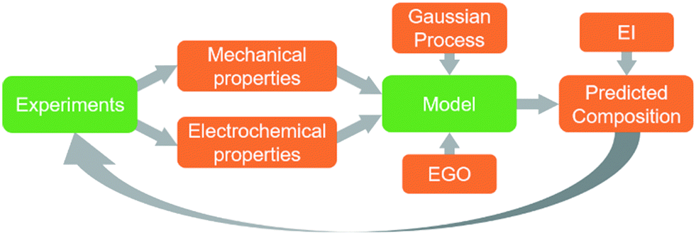
Here we present the first use of machine learning on the design of structural electrodes for energy and power. We first refine and re-examine Wetzel's utility metric in order to broaden its applicability to a wider design space. By doing so, we present a customizable utility function that allows the user to adjustably weight the electrochemical and the mechanical performance metrics. This utility function guides the design of the electrodes toward different regions of the design space based on the application. The primary degrees of freedom in the material system considered in this work are the weight percentages of the electrode's constituents (rGO/ANFs/CNTs). Herein, we focus on the combination of data science and experiments to establish high-level connections between the composition and the electrochemical and mechanical properties. Data driven models, in the form of Gaussian processes, are used to establish links between composition and performance without any knowledge of the complex physical interactions within the electrode. These models are used to predict compositions with promising combinations of properties which are then validated experimentally, within a Bayesian optimization framework. This process is performed multiple times, creating a feedback loop for efficient exploration of the design space. We apply this methodology to the rGO/ANF/CNT supercapacitor system as a test case.
2. Methodology
2.1 Design problem
In order for these tools to be combined in an effective way it is necessary to establish a description of the system in terms of functional dependencies. This is first done at the component level to better understand how a structural energy storage device might operate within an overall system. The component level functional model indicates the appropriate performance metrics and properties to consider in the material level functional model. The material level functional model captures relationships between the process, structure, properties, and performance in the form of a system chart similar to the type outlined in Olson's report on the design of materials.63 The material level functional model allows for a fair assessment of how to best combine data, models, and experiments at the appropriate levels of abstraction.A functional diagram for a structural electrode is used to better understand the relationships between inputs and outputs at the component level, Fig. 1a. Also, it is used to inform decisions concerning the best way to manipulate functions and sub-functions to achieve objectives and goals. At the component level, Fig. 1a, the function of a structural electrode is to store and deliver energy to a system while still being safe and stable after sustaining mechanical loads and forces. This requires the consideration of both electrochemical and mechanical requirements.21
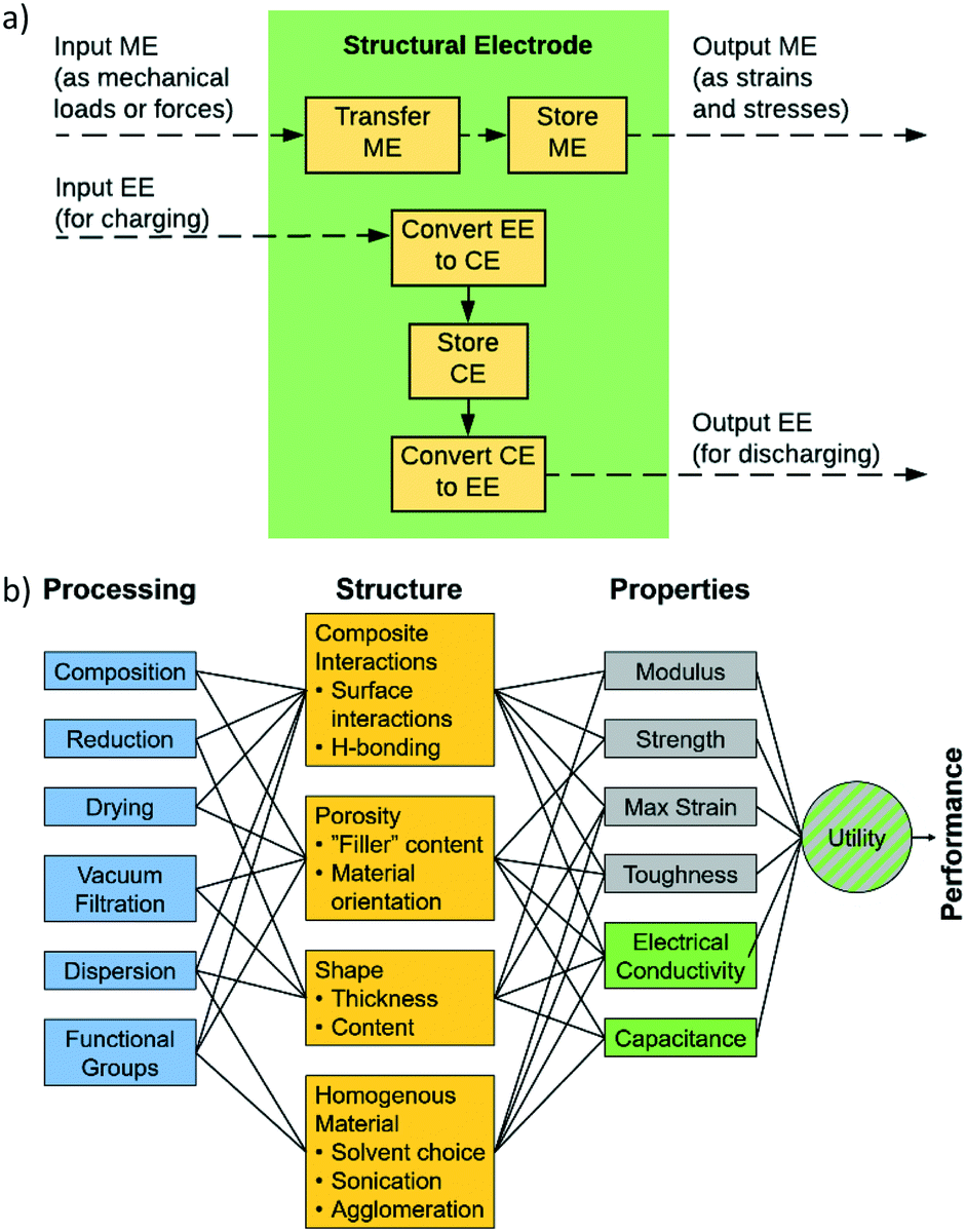 | ||
| Fig. 1 (a) Component level functional diagram of a typical structural electrode where ME is mechanical energy, EE is electrical energy, and CE is chemical energy. In this diagram, the structural electrode can discharge electrical energy while also safely handling mechanical loads. (b) Material level system chart of the interactions between the process, structure, and properties within a composite electrode consisting of ANFs, graphene, and CNTs. | ||
As stated above, the three potential materials of interest for designing a multifunctional energy storage device are rGO, ANFs, and CNTs. The system chart, Fig. 1b, summarizes the fundamental functional interactions between the various levels of the process–structure–property (PSP) hierarchy for composite electrodes that contain these components. For example, composition directly affects the composite interactions and porosity of the structure, which, in-turn, affect the electrochemical and mechanical properties listed.
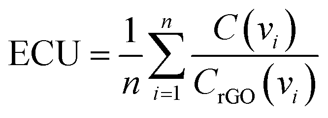
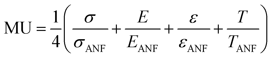
In order to effectively design a new material, the mechanical and electrochemical properties should be combined into a single performance metric (U, which varies from 0 to 1) through a utility function which combines electrochemical utility (ECU) and mechanical utility (MU). Eqn (1)–(3) define the utility based on a combination of various performance metrics where a is a weighting coefficient (which varies from 0 to 1), C is the specific capacitance of the electrode at different scan rates ν, T is the toughness, σ is the ultimate tensile strength, E is the Young's modulus, and ε is the strain at break. These performance metrics were normalized by the typical values for pure reduced graphene oxide electrodes and pure ANF films denoted by subscript rGO and subscript ANF, respectively. This means that the ternary composite materials are compared against pure reduced graphene oxide, a commonly investigated material for supercapacitor electrodes, and pure ANF which is known for its mechanical properties. This allows the utility function to reflect the change in the performance relative to the highest performing unary component. ECU describes the capacitance values at 6 different scan rates (ν = 1, 5, 10, 20, 50, and 100 mV s−1) to take both energy storage and rate capability into account. MU examines 4 important metrics for structural materials and combines them with equal weighting. The value of a is chosen to bias the relative importance of electrochemical performance against mechanical performance based on the intended application. For this work, a was set to 0.5.
| U = (1 − a)ECU + (a)MU | (1) |
 | (2) |
 | (3) |
2.2 Model development
While using one set of experimental data is beneficial, there are also challenges to this approach. The experimental data available only explore a small portion of the entire design space as shown in Fig. 2. This may cause problems in modeling the entire space because the model will have inaccurate predictions away from the data heavy corner. However, it is not necessary to explore the entire design space. Previous studies in the area of multifunctional composites showed that using ANFs or CNTs as additives (in small quantities) provides a large enhancement in the mechanical and electrochemical performance, respectively.33,35,36,39–42,50,53 Also, exploring high graphene content composites better tailors this analysis to energy storage applications since graphene acts as the primary electroactive component in the composite. Reducing the design space to consider only high graphene content and low ANF and CNT content will provide the best analysis into multifunctional energy storage devices with the current experimental dataset available.
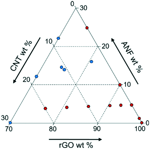 | ||
| Fig. 2 Ternary diagram describing the design space for rGO/ANF/CNT supercapacitor electrodes. Original experimental data are plotted with red circles while predicted compositions which were then validated experimentally are plotted with blue circles. | ||
 | ||
| Fig. 3 Schematic showing feedback between the experimental data and the computational model. EI is expected improvement and EGO is efficient global optimization. | ||
In order to effectively create a model from this dataset, appropriate representations of the expected response surface of such a model must be established. GPMs describe the expected behavior of the experiment's response surface according to the sensitivity of the data to each control variable and the (statistical) correlation between points in the design space. The GPM is a non-parametric model such that there is no assumed functional form of the solution. As such, the model avoids the issue of underfitting or overfitting. Sensitivity and correlation are encoded in a “kernel function” through the use of hyperparameters which represent the characteristic length and correlation distance of the response surface, respectively. Selection of the kernel's functional form (Matern, radial basis functions (RBFs), etc.) is often based on the expected nature of the response surface a priori. Multiple kernels were tested and compared based on their predicted surfaces. With an appropriate kernel and relevant hyperparameters defined, the GPM was fit to a dataset by finding hyperparameter values that minimized the error between the response surface and the data points. The GPM, with optimized hyperparameters, is then used to predict the mean and variance of the response surface for the entire design space. The models are obtained from Scikit-learn, a free machine learning library. Kennedy et al. also detailed the Bayesian calibration process employed in Gaussian process regression.66
Predicted response surfaces of GPMs were then used, in conjunction with a leave-one-out (LOO) cross validation technique, to find the most predictive feature set. Four feature sets (ANFs/rGO, ANFs/CNTs, rGO/CNTs, rGO/ANFs/CNTs) were analyzed using this technique. In the LOO analysis, one point was removed from the dataset and the model was trained on the remaining data. The error of the model was calculated as the difference between the model's predicted value and the actual value at the removed point. This process was repeated until all data points have been sampled. Each feature set was analyzed with this approach and the resulting distributions of errors were compared to select the best feature set. A summary of these analyses is given in the Results and discussion section.
Once the final GPM and feature set combination were determined, the mean and variance predictions of the model were used with acquisition criteria to select new potential experiments. The choice of acquisition criteria depends on the objective of the design problem. Since the objective of this work was to optimize the performance of a supercapacitor electrode, criteria that sought the optimum value in a design space were chosen: upper confidence bound (UCB), probability of improvement (PI), and expected improvement (EI). It is important to note that materials informatics methods can also be used to identify properties that conflict with the design goal, as these would also provide valuable knowledge; however, they are used here to identify the best composition for future experimental design work.
UCB, the simplest approach, selects new experimental points by finding the maximum value when the mean and variance surfaces are added together. While easy to calculate, UCB has the drawback of a slow convergence rate if the predicted variance dominates the mean response. PI selects the next experiment by finding the point in the design space that has the largest region of probability distribution above a predefined target value of optimization. This target value is typically selected as the best point found so far plus a constant value. The magnitude of this constant term determines the behavior of the search criteria with large values promoting exploration and small values promoting exploitation. The main issue with PI is the need to select this target offset a priori. EI extends the idea of PI by including information about the centroid of the same area considered by PI. By using the centroid, EI considers both probability and magnitude of the improvement.67 This provides a balance between exploration and exploitation in which points that have lower probability but larger magnitudes of improvement can be selected over points with higher probability but lower potential improvement in the response surface. Analysis of these acquisition criteria for this particular design problem can be seen in section 3.2 below. Finally, the efficacy of EGO to balance exploration of the design space and exploitation of promising areas has been thoroughly proven by Jones et al.64 Thus, the model can obtain a global optimality and avoid local minima.
All code and data pertaining to this work is available on Github under the repository titled Design-of-Multifunctional-Supercapacitor-Electrodes-using-an-Informatics-Approach. (https://github.com/AnishGPatel/Design-of-Multifunctional-Supercapacitor-Electrodes-using-an-Informatics-Approach).
2.3 Experimental
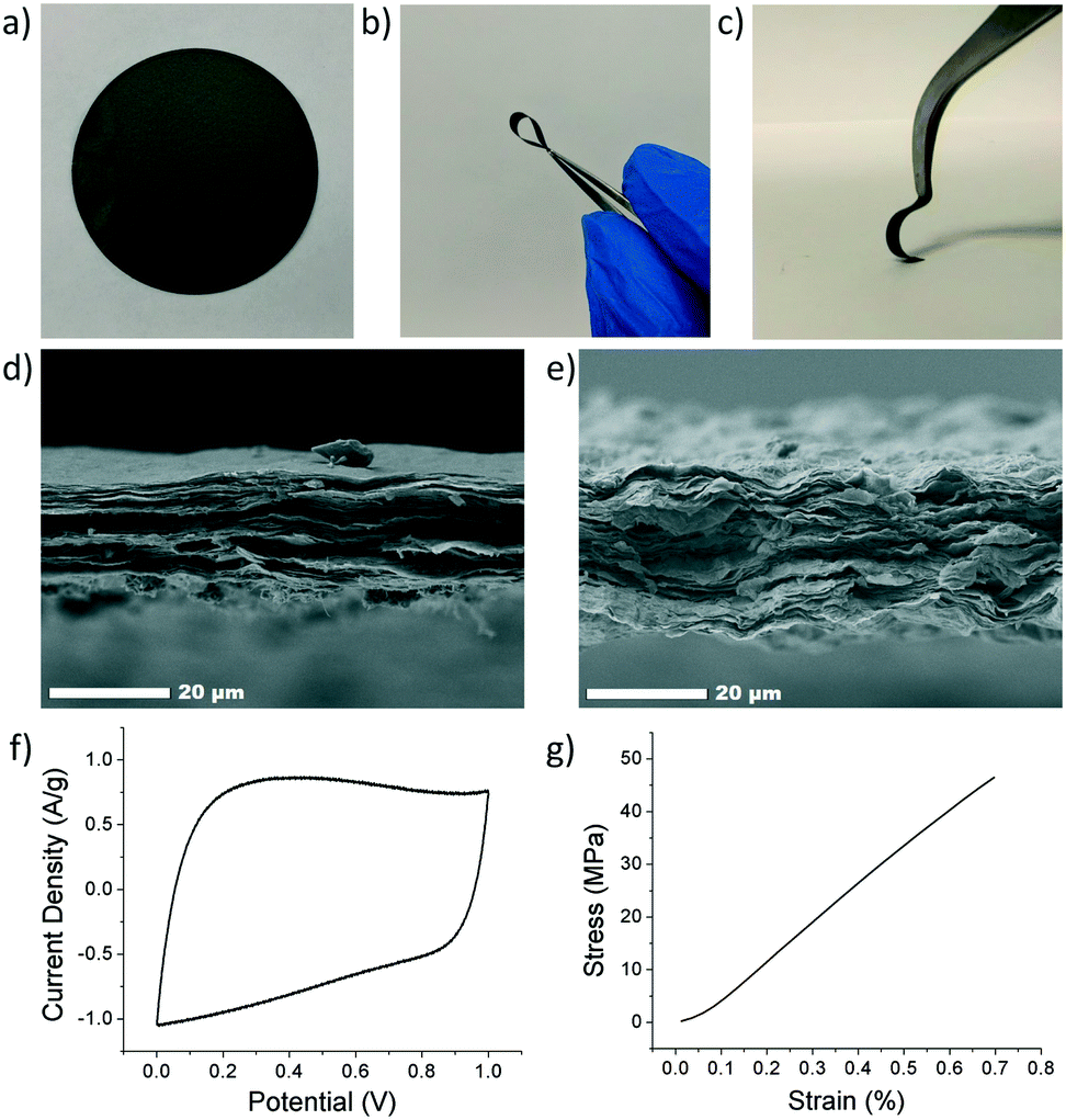 | ||
| Fig. 4 Digital images of (a) an rGO electrode and (b and c) an rGO/ANF composite electrode (no CNTs). Cross-sectional SEM images of (d) an rGO/ANF electrode without CNTs (95/5 wt% rGO/ANFs) and (e) with 20 wt% CNTs (76/4/20 wt% rGO/ANFs/CNTs). (f) A representative cyclic voltammogram and (g) a typical stress–strain curve for an rGO/ANF/CNT composite electrode (90.25 wt% rGO, 4.75 wt% ANFs, 5 wt% CNTs). | ||
The composite electrode's thickness was characterized using scanning electron microscopy (SEM, JEOL JSM-7500F). Average thicknesses of 15–30 μm were obtained. Cross-sectional SEM imaging of the composite revealed a tightly packed and layered structure, Fig. 4d and e. However, the ANFs and CNTs were not directly observed due to their small size and low loading in the composite. CNTs were characterized using transmission electron microscopy (TEM, JEOL JEN-2010), Fig. S1.† Samples were prepared by drop casting a solution of CNTs in DMSO directly onto a TEM grid.
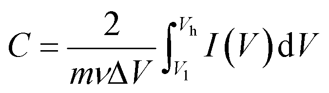
Electrochemical characterization was carried out using cyclic voltammetry (CV) on both a Gamry potentiostat and Arbin instrument (Gamry Interface 1000, Gamry Instruments and Arbin Battery Testing Instrument). The electrochemical performance was tested using a two-electrode symmetric coin cell with 6 M KOH as the electrolyte. The coin cell consisted of, from bottom to top, a bottom metal covering, carbon paper current collector, electrode, electrolyte, separator (Celgard 3501), electrolyte, electrode, current collector, spacer, spring, and metal covering. The electrodes were prepared by cutting a 16 mm circle sample out of the composite electrode. Cyclic voltammetry was conducted at varying scan rates from a voltage of 0 to 1 V. Specific capacitance (F g−1) was calculated from CV curves using eqn (4), where m is the mass of the two electrodes (g), ν is the scan rate (V s−1), ΔV is the voltage range (V), Vl is the low-voltage cutoff (V), Vh is the high-voltage cutoff (V), and I is the current (A). Fig. 4f shows a CV curve for an rGO/ANF/CNT composite with 90.25 wt% rGO, 4.75 wt% ANFs, and 5 wt% CNTs at 20 mV s−1. The electrode stores energy through the electric double layer (EDL) capacitance. This is evident through the lack of redox peaks in the CV curves and the rectangular shape of the curve, which indicates ideal capacitive behavior.
 | (4) |
The mechanical performance was evaluated using quasi-static uniaxial tensile testing using a dynamic mechanical analyser (DMA Q800, TA Instruments). The electrode was cut into rectangular strips approximately 2.5 mm in width and 20 mm in height, with thicknesses ranging from 15 to 30 μm. The electrode samples were gripped using a thin film tension clamp with a clamp compliance of about 0.2 μm N−1, and the tensile tests were conducted in controlled strain rate mode with a preload of 0.02 N and a strain ramp rate of 0.1% min−1. A typical stress–strain curve of an rGO/ANF/CNT composite with 90.25 wt% rGO, 4.75 wt% ANFs, and 5 wt% CNTs obtained from tensile testing is shown in Fig. 4g. The mechanical properties obtained from the stress–strain curve include Young's modulus, strength, ultimate strain, and toughness.
3. Results and discussion
3.1 Feature selection
Utility for the initial experimental data was calculated using eqn (1)–(3) with an a value of 0.5, indicating equal weighting of both the electrochemical and mechanical utility. The relationship between the three features (rGO wt%, ANF wt%, and CNT wt%) and utility is shown in in Fig. 5a–c. This shows that the regression model can be used to establish a direct link between composition and performance. The features that are selected all affect the value of utility in a noticeable way. However, a single feature alone cannot explain the utility values and cannot capture the design space. For example, from Fig. 5c, which focuses on CNT wt% as the single feature, it is evident that multiple samples with 0 wt% CNT have different utility values and that additional information from other features would be required in order to accurately predict the behavior of the composites. This can also be seen with ANF wt% as a feature, Fig. 5b. Feature selection is required to find the best combination of features that can model the design space. Lookman et al. also found that composition dependent features can be used to predict performance and guide experimental exploration of the design space.65,68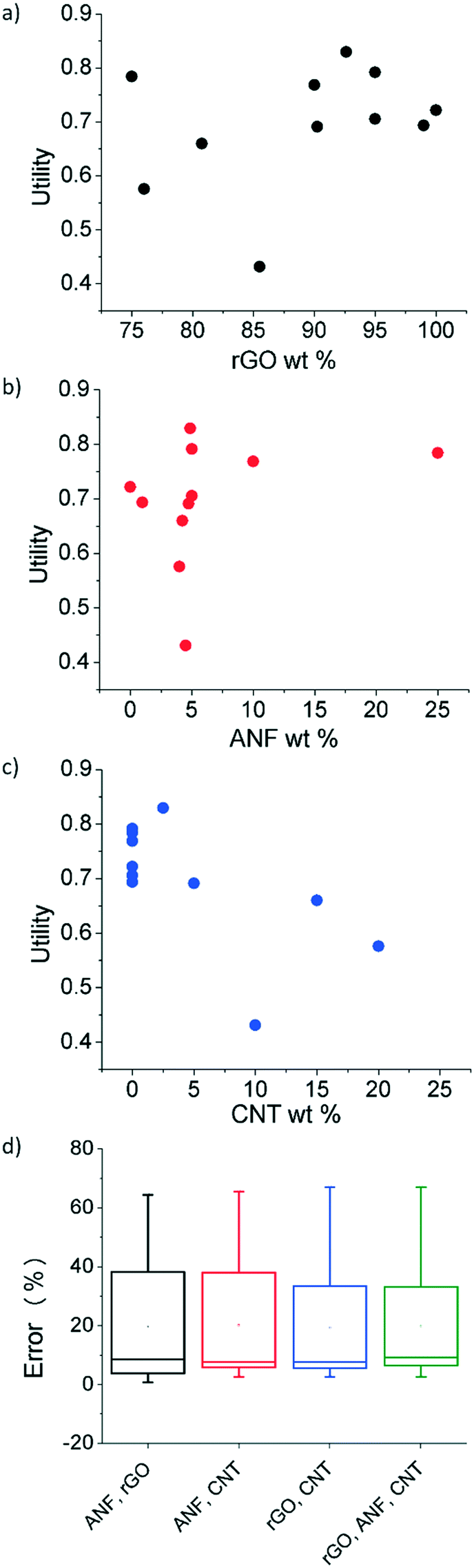 | ||
| Fig. 5 Utility values for the features (a) GO wt%, (b) ANF wt%, and (c) CNT wt% for each experimental data point. (d) Leave-one-out cross validation error of four different feature sets. Boxes are a statistical representation of the distribution of errors for each feature set. The top and bottom lines are the maximum and minimum data points, the top and bottom of the box are the 75th and 25th percentile markers, the middle line is the median, and the point within the box is the mean. | ||
Feature selection was used to find the most predictive feature set. Four combinations of the three features (ANF/rGO, ANF/CNT, rGO/CNT, rGO/ANF/CNT) were tested using leave-one-out cross validation, as shown in Fig. 5d. The unary feature sets were disregarded due to their inability to describe complete compositions. Unary feature sets would prevent experimental validation of predicted compositions. Each feature set performed almost identically. The leave-one-out error for the complete feature set (rGO/ANF/CNT) was 19.9% while the errors for the feature sets ANF/rGO, ANF/CNT, and rGO/CNT were 19.6%, 20.1%, and 19.3%, respectively. The uniformity in errors is expected because all four feature sets contain enough information to define the entire system in terms of composition due to mass conservation constraints. The complete feature set with all three features (rGO wt%, ANF wt%, and CNT wt%) was used as it contained the most information and performed as good as the other feature sets. Leave-one-out cross-validation trains the model by using all the experimental data except for one data point and then validates using the data point that was initially left out. This is then repeated until each data point is used to validate the feature set. Analysis of variance (ANOVA) was used to compare the variance between the 4 feature sets. There was no statistical difference between the errors of the different feature sets meaning that the averages of the errors of the four feature sets obtained using leave-one-out cross validation are all equal.
3.2 Response surface
After considering multiple kernels, a combination of two RBF kernels with different characteristic length limits was chosen to allow the hyperparameter optimization subroutine to identify multiple characteristic frequencies of the response surface. In other words, the use of these two RBF kernels allows the response surface and acquisition criteria to balance exploration and exploitation. The two kernels prevent the model from being trapped in local maxima but limit exploration so that the potential absolute maxima can be identified properly. A predictive model of the utility, calculated using this kernel, was obtained using the regression techniques described in section 2.2.2 and using the initial experimental data. Plots of this utility and standard deviation vs. electrode composition are displayed in Fig. 6 with the design space defined as 0–30 wt% ANFs, 0–30 wt% CNTs, and 70–100 wt% graphene. The model indicates that the utility is highest for high rGO loading (>95 wt%). However, the model also shows the potential for promising compositions near 80 wt% rGO, 5 wt% ANFs, and 15 wt% CNTs. This is most likely because high rGO loading will lead to high capacitance values as it is the main contributor in the composite due to its high surface area and electrical conductivity. CNTs can also contribute to the capacitance of the electrode while also potentially imparting improved mechanical properties due to strong π–π interactions between the CNTs, rGO, ANFs. Finally, adding ANFs in small amounts will slightly reduce the specific capacitance of the electrode as it is an electrically insulating material and will not contribute to the capacitance. However, ANFs will greatly improve the mechanical properties by strongly associating with the rGO sheets through hydrogen bonding and π–π stacking.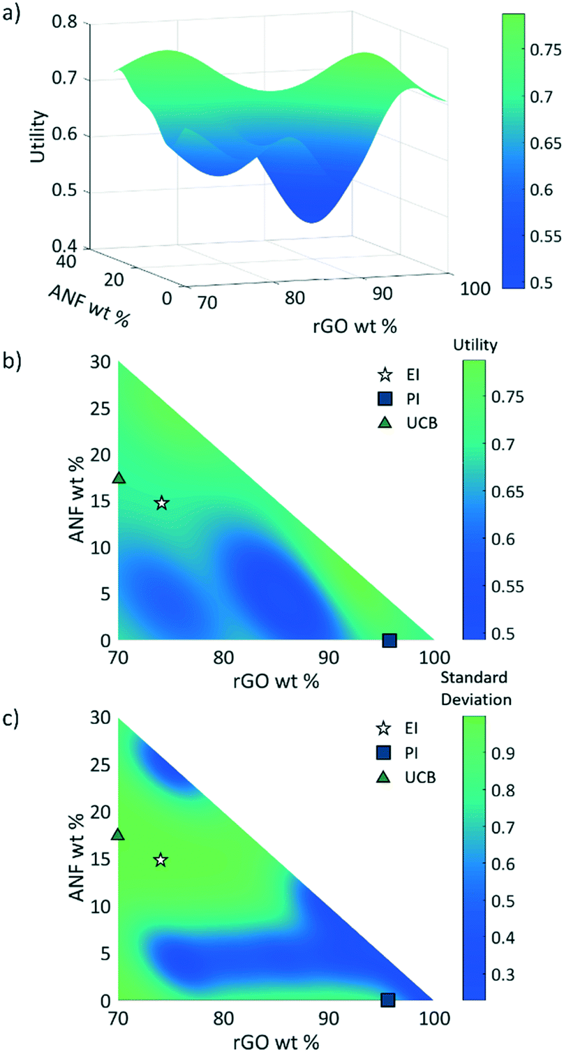 | ||
| Fig. 6 Three-dimensional plot of (a) utility and contour plots of (b) utility and (c) standard deviation vs. composition. Circular points represent the initial experimental data while the star, square, and triangle represent recommendations from the model based on either expected improvement (EI), probability of improvement (PI), or upper confidence bound (UCB), respectively. | ||
The three acquisition criteria, expected improvement (EI), probability of improvement (PI), and upper confidence bound (UCB) (white star, blue square, and green triangle, respectively, in Fig. 6b and c), all point to different locations on the utility surface. UCB (green triangle) indicates the point that has the maximum possible utility value when examining both the mean and variance, PI (blue square) describes the highest probability of improvement, and EI (white star) takes both the probability and magnitude of improvement into consideration. In this work, EI is selected as the acquisition criterion instead of PI due to its lack of sensitivity to the target offset value. The selection points for PI and UCB are plotted in Fig. 6b and c along with EI selection points for comparison. Both UCB and EI recommend testing in areas that have high variance, or areas that have not been experimentally probed. This is because the model requires more information across the design space (exploration) before it can begin to search for a maximum (exploitation). PI indicates a composition near the highest experimental utility composition because it exhibits a high chance of very minor improvement. The EI predicted optimal composition for the first iteration was 74 wt% rGO, 14.5 wt% ANFs, and 11.5 wt% CNTs. As shown in Fig. 3, the predicted composition was synthesized experimentally and its mechanical and electrochemical properties were characterized according to the methods described in sections 2.3 and S1.† The properties of the new composition are then used to update the mean and variance of the utility predictions. This process constitutes one iteration and is repeated to find the composition with the highest utility.
The first iteration was found to have the highest utility of the predicted compositions of U = 0.875 for 74 wt% rGO, 15.5 wt% ANFs, and 11.5 wt% CNTs, Fig. 7b. Not only that this was the highest predicted utility, but it was also higher than the utilities obtained from the initial experimental data. The model was able to find a composition that had a 5.5% improvement in utility over the best performing composite (92.625 wt% rGO, 4.875 wt% ANFs, and 2.5 wt% CNTs) from the initial experimental data. The new composition also had a Young's modulus of 18.9 GPa and a strength of 66.3 MPa, which corresponded to an increase of 78.8% and 34.0%, respectively, relative to the highest performing initial experimental composition. However, the capacitance at 1 mV s−1 was 117.2 F g−1, representing a 29.6% decrease. This is because the model equally weights the mechanical and electrochemical performance while the initial experimental data prioritize the electrochemical performance over the mechanical performance due to being focused around high rGO loadings.
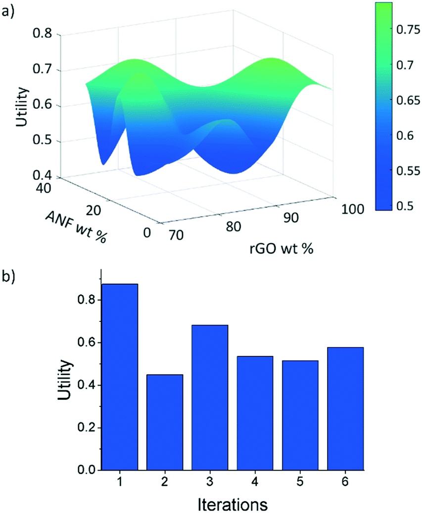 | ||
| Fig. 7 (a) Predicted utility function after 6 iterations and (b) utility of samples with composition predicted by EI at each iteration. | ||
The model next explored relatively high ANF content compositions (such as 70 wt% rGO, 22 wt% ANFs, and 8 wt% CNTs) only to find the utility in those areas to be fairly low. This is due to the low surface area of the electrically conductive material in the composite resulting from the low rGO content. This caused low capacitance values and poor cycle stability leading to a reduced ECU. The model then recommended relatively high CNT content compositions (such as 70 wt% rGO, 0 wt% ANFs, and 30 wt% CNTs). While the high CNT content electrodes performed well electrochemically (due to the CNTs contribution to the capacitance), the mechanical properties were found to be low due to the lack of a mechanical nanofiller. This led to reduced interactions between the electrode components and a reduced mechanical utility.
After 6 iterations, the utility surface predicted using the model, Fig. 7a, changed drastically as compared to the predicted utility using only the initial experimental data, Fig. 6a. These results are significant because we were able to find the highest utility composition (74 wt% rGO, 15.5 wt% ANFs, and 11.5 wt% CNTs) in an area of the design space that would not have been explored as rapidly when using only experimental approaches. The use of materials informatics reduced the number of experiments that would have been required to find this optimal composition when compared to systematically exploring the design space. Furthermore, the model gives additional insight into the trade-offs between the electrochemical and mechanical performance when considering composite materials by predicting maxima and minima in the response surface at certain compositions.
Conclusions
In summary, functional analysis was used to identify the variables that control the electrochemical and mechanical properties of a composite electrode. This process provided valuable information regarding what properties (electrode composition, capacitance, Young's modulus, strength, ultimate strain, and toughness) would be of interest in this work. This method has great potential in other areas of materials science by identifying key aspects of a materials problem that controls desired performances or outcomes. The use of this approach can also aid in the discovery and understanding of functional relationships in a materials problem which can lead to more accurate solutions that directly target the appropriate inputs. With these properties, a utility function was developed for evaluating the performance of the multifunctional material. The utility incorporated material properties such as specific capacitance, strength, Young's modulus, ultimate strain, and toughness. These properties were combined in a weighted fashion to allow for adaptation to user preferences of the electrode's electrochemical or mechanical properties. Next, feature selection, using leave-one-out cross validation, was performed to find the subset of features that captured the response surface most accurately. From this feature set analysis, a Gaussian process regression model that used rGO wt%, ANF wt%, and CNT wt% as features was selected and fitted to the data by tuning the hyperparameters. EI was used as the acquisition method for predicting the next best composition to test experimentally. After 6 iterations, the model identified a maximum in the design space in a previously unexplored area. The model was able to find a composition with a higher overall utility (5.5% increase), Young's modulus (78.8% increase), and strength (34.0% increase) than the best initial experimental composition. This approach can be used to map out the design space in an optimal manner reducing the number of experiments required to find the optimal combination of rGO, ANFs, and CNTs for multifunctional structural energy and power.Conflicts of interest
There are no conflicts of interest to declare.Acknowledgements
This work was supported by the Air Force Office of Scientific Research (grant no. FA9550-16-1-0230, experimental work) and by the National Science Foundation Research Traineeship Data-enabled Discovery and Design of Energy Materials (grant no. 1545403, computational work).References
- Y. Zhu, S. Murali, M. D. Stoller, K. Ganesh, W. Cai, P. J. Ferreira, A. Pirkle, R. M. Wallace, K. A. Cychosz and M. Thommes, Science, 2011, 332, 1537–1541 CrossRef CAS.
- M. D. Stoller, S. Park, Y. Zhu, J. An and R. S. Ruoff, Nano Lett., 2008, 8, 3498–3502 CrossRef CAS PubMed.
- M. Pumera, Energy Environ. Sci., 2011, 4, 668–674 RSC.
- R. Raccichini, A. Varzi, S. Passerini and B. Scrosati, Nat. Mater., 2015, 14, 271 CrossRef CAS PubMed.
- X. Yang, C. Cheng, Y. Wang, L. Qiu and D. Li, Science, 2013, 341, 534–537 CrossRef CAS PubMed.
- P. G. Balakrishnan, R. Ramesh and T. Prem Kumar, J. Power Sources, 2006, 155, 401–414 CrossRef CAS.
- M. Armand and J. M. Tarascon, Nature, 2008, 451, 652 CrossRef CAS PubMed.
- J. B. Goodenough and Y. Kim, Chem. Mater., 2010, 22, 587–603 CrossRef CAS.
- H. Wu, D. Zhuo, D. Kong and Y. Cui, Nat. Commun., 2014, 5, 5193 CrossRef CAS PubMed.
- N. Shirshova, H. Qian, M. Houllé, J. H. Steinke, A. R. Kucernak, Q. P. Fontana, E. S. Greenhalgh, A. Bismarck and M. S. Shaffer, Faraday Discuss., 2014, 172, 81–103 RSC.
- J. F. Snyder, R. H. Carter and E. D. Wetzel, Chem. Mater., 2007, 19, 3793–3801 CrossRef CAS.
- Z. Ling, C. E. Ren, M.-Q. Zhao, J. Yang, J. M. Giammarco, J. Qiu, M. W. Barsoum and Y. Gogotsi, Proc. Natl. Acad. Sci. U. S. A., 2014, 111, 16676–16681 CrossRef CAS PubMed.
- H. An, J. Mike, K. A. Smith, L. Swank, Y.-H. Lin, S. L. Pesek, R. Verduzco and J. L. Lutkenhaus, Sci. Rep., 2015, 5, 14166 CrossRef CAS PubMed.
- M. F. El-Kady, V. Strong, S. Dubin and R. B. Kaner, Science, 2012, 335, 1326–1330 CrossRef CAS PubMed.
- L. Nyholm, G. Nyström, A. Mihranyan and M. Strømme, Adv. Mater., 2011, 23, 3751–3769 CAS.
- L. E. Asp and E. S. Greenhalgh, Compos. Sci. Technol., 2014, 101, 41–61 CrossRef CAS.
- E. Greenhalgh, J. Ankersen, L. Asp, A. Bismarck, Q. Fontana, M. Houlle, G. Kalinka, A. Kucernak, M. Mistry, S. Nguyen, H. Qian, M. Shaffer, N. Shirshova, J. Steinke and M. Wienrich, J. Compos. Mater., 2015, 49, 1823–1834 CrossRef CAS.
- S. R. Kwon, J. Harris, T. Zhou, D. Loufakis, J. G. Boyd and J. L. Lutkenhaus, ACS Nano, 2017, 11, 6682–6690 CrossRef CAS PubMed.
- S. R. Kwon, M. B. Elinski, J. D. Batteas and J. L. Lutkenhaus, ACS Appl. Mater. Interfaces, 2017, 9, 17125–17135 CrossRef CAS PubMed.
- N. Shirshova, H. Qian, M. S. P. Shaffer, J. H. G. Steinke, E. S. Greenhalgh, P. T. Curtis, A. Kucernak and A. Bismarck, Composites, Part A, 2013, 46, 96–107 CrossRef CAS.
- D. J. O'Brien, D. M. Baechle and E. D. Wetzel, J. Compos. Mater., 2011, 45, 2797–2809 CrossRef.
- R. F. Gibson, Compos. Struct., 2010, 92, 2793–2810 CrossRef.
- J. P. Thomas and M. A. Qidwai, Acta Mater., 2004, 52, 2155–2164 CrossRef CAS.
- S. Curtarolo, G. L. W. Hart, M. B. Nardelli, N. Mingo, S. Sanvito and O. Levy, Nat. Mater., 2013, 12, 191 CrossRef CAS PubMed.
- K. Hatakeyama-Sato, T. Tezuka, Y. Nishikitani, H. Nishide and K. Oyaizu, Chem. Lett., 2019, 48, 130–132 CrossRef.
- J. Hattrick-Simpers, C. Wen and J. Lauterbach, Catal. Lett., 2015, 145, 290–298 CrossRef CAS.
- J. R. Hattrick-Simpers, K. Choudhary and C. Corgnale, Mol. Syst. Des. Eng., 2018, 3, 509–517 RSC.
- S. V. Kalinin, B. G. Sumpter and R. K. Archibald, Nat. Mater., 2015, 14, 973 CrossRef CAS PubMed.
- A. Mannodi-Kanakkithodi, G. Pilania, T. D. Huan, T. Lookman and R. Ramprasad, Sci. Rep., 2016, 6, 20952 CrossRef PubMed.
- P. Pankajakshan, S. Sanyal, O. E. de Noord, I. Bhattacharya, A. Bhattacharyya and U. Waghmare, Chem. Mater., 2017, 29, 4190–4201 CrossRef CAS.
- H. Chen, M. B. Müller, K. J. Gilmore, G. G. Wallace and D. Li, Adv. Mater., 2008, 20, 3557–3561 CrossRef CAS.
- Y. Zhu, S. Murali, W. Cai, X. Li, J. W. Suk, J. R. Potts and R. S. Ruoff, Adv. Mater., 2010, 22, 3906–3924 CrossRef CAS PubMed.
- K. Cao, C. P. Siepermann, M. Yang, A. M. Waas, N. A. Kotov, M. D. Thouless and E. M. Arruda, Adv. Funct. Mater., 2013, 23, 2072–2080 CrossRef CAS.
- M. Yang, K. Cao, L. Sui, Y. Qi, J. Zhu, A. Waas, E. M. Arruda, J. Kieffer, M. D. Thouless and N. A. Kotov, ACS Nano, 2011, 5, 6945–6954 CrossRef CAS PubMed.
- M. Yang, K. Cao, B. Yeom, M. Thouless, A. Waas, E. M. Arruda and N. A. Kotov, J. Compos. Mater., 2015, 49, 1873–1879 CrossRef CAS.
- J. Zhu, W. Cao, M. Yue, Y. Hou, J. Han and M. Yang, ACS Nano, 2015, 9, 2489–2501 CrossRef CAS PubMed.
- J. R. Potts, D. R. Dreyer, C. W. Bielawski and R. S. Ruoff, Polymer, 2011, 52, 5–25 CrossRef CAS.
- M. Ghislandi, E. Tkalya, S. Schillinger, C. E. Koning and G. de With, Compos. Sci. Technol., 2013, 80, 16–22 CrossRef CAS.
- B. Park, W. Lee, E. Lee, S. H. Min and B.-S. Kim, ACS Appl. Mater. Interfaces, 2015, 7, 3329–3334 CrossRef CAS PubMed.
- J. Fan, J. Wang, Z. Shi, S. Yu and J. Yin, Mater. Chem. Phys., 2013, 141, 861–868 CrossRef CAS.
- J. Fan, Z. Shi, L. Zhang, J. Wang and J. Yin, Nanoscale, 2012, 4, 7046–7055 RSC.
- J. Fan, Z. Shi, M. Tian and J. Yin, RSC Adv., 2013, 3, 17664–17667 RSC.
- M. J. Treacy, T. Ebbesen and J. Gibson, Nature, 1996, 381, 678 CrossRef CAS.
- T. Ebbesen, H. Lezec, H. Hiura, J. Bennett, H. Ghaemi and T. Thio, Nature, 1996, 382, 54 CrossRef CAS.
- P. Kim, L. Shi, A. Majumdar and P. McEuen, Phys. Rev. Lett., 2001, 87, 215502 CrossRef CAS PubMed.
- S. Hu, R. Rajamani and X. Yu, Appl. Phys. Lett., 2012, 100, 104103 CrossRef.
- Z. Fan, J. Yan, L. Zhi, Q. Zhang, T. Wei, J. Feng, M. Zhang, W. Qian and F. Wei, Adv. Mater., 2010, 22, 3723–3728 CrossRef CAS PubMed.
- D. Yu and L. Dai, J. Phys. Chem. Lett., 2009, 1, 467–470 CrossRef.
- V. Gupta and N. Miura, Electrochim. Acta, 2006, 52, 1721–1726 CrossRef CAS.
- V. Subramanian, H. Zhu and B. Wei, Electrochem. Commun., 2006, 8, 827–832 CrossRef CAS.
- S. Stankovich, D. A. Dikin, R. D. Piner, K. A. Kohlhaas, A. Kleinhammes, Y. Jia, Y. Wu, S. T. Nguyen and R. S. Ruoff, Carbon, 2007, 45, 1558–1565 CrossRef CAS.
- D. T. Pham, T. H. Lee, D. H. Luong, F. Yao, A. Ghosh, V. T. Le, T. H. Kim, B. Li, J. Chang and Y. H. Lee, ACS Nano, 2015, 9, 2018–2027 CrossRef CAS.
- Q. Cheng, J. Tang, J. Ma, H. Zhang, N. Shinya and L.-C. Qin, Phys. Chem. Chem. Phys., 2011, 13, 17615–17624 RSC.
- G. Hautier, C. C. Fischer, A. Jain, T. Mueller and G. Ceder, Chem. Mater., 2010, 22, 3762–3767 CrossRef CAS.
- H. Li, C. R. Collins, T. G. Ribelli, K. Matyjaszewski, G. J. Gordon, T. Kowalewski and D. J. Yaron, Mol. Syst. Des. Eng., 2018, 3, 496–508 RSC.
- J. Ling, M. Hutchinson, E. Antono, S. Paradiso and B. Meredig, Integr. Mater. Manuf. Innov., 2017, 6, 207–217 CrossRef.
- B. C. Rinderspacher and J. M. Elward, Mol. Syst. Des. Eng., 2018, 3, 485–495 RSC.
- S. K. Suram, J. A. Haber, J. Jin and J. M. Gregoire, ACS Comb. Sci., 2015, 17, 224–233 CrossRef CAS PubMed.
- R. J. Xu, J. H. Olshansky, P. D. F. Adler, Y. Huang, M. D. Smith, M. Zeller, J. Schrier and A. J. Norquist, Mol. Syst. Des. Eng., 2018, 3, 473–484 RSC.
- D. D. Landis, J. S. Hummelshøj, S. Nestorov, J. Greeley, M. Dułak, T. Bligaard, J. K. Nørskov and K. W. Jacobsen, Comput. Sci. Eng., 2012, 14, 51–57 Search PubMed.
- L. Ghadbeigi, J. K. Harada, B. R. Lettiere and T. D. Sparks, Energy Environ. Sci., 2015, 8, 1640–1650 RSC.
- A. O. Oliynyk, E. Antono, T. D. Sparks, L. Ghadbeigi, M. W. Gaultois, B. Meredig and A. Mar, Chem. Mater., 2016, 28, 7324–7331 CrossRef CAS.
- G. B. Olson, Science, 1997, 277, 1237–1242 CrossRef CAS.
- D. R. Jones, M. Schonlau and W. J. Welch, J. Glob. Optim., 1998, 13, 455–492 CrossRef.
- T. Lookman, F. J. Alexander and K. Rajan, Information Science for Materials Discovery and Design, Springer, 2016 Search PubMed.
- M. C. Kennedy and A. O'Hagan, J. R. Stat. Soc. Series B Stat. Methodol., 2001, 63, 425–464 CrossRef.
- E. Brochu, V. M. Cora and N. De Freitas, 2010, arXiv preprint arXiv:1012.2599.
- P. V. Balachandran, J. Theiler, J. M. Rondinelli and T. Lookman, Sci. Rep., 2015, 5, 13285 CrossRef CAS PubMed.
Footnote |
| † Electronic supplementary information (ESI) available. See DOI: 10.1039/c8me00060c |
| This journal is © The Royal Society of Chemistry 2019 |