
Digital nanoliter to milliliter flow rate sensor with in vivo demonstration for continuous sweat rate measurement†
Jessica
Francis
 a,
Isaac
Stamper
a,
Jason
Heikenfeld
ab and
Eliot F.
Gomez
*a
a,
Isaac
Stamper
a,
Jason
Heikenfeld
ab and
Eliot F.
Gomez
*a
aDepartment of Biomedical Engineering, University of Cincinnati, Cincinnati, OH 45221, USA. E-mail: gomezef@ucmail.uc.edu
bDepartment of Electrical Engineering & Computer Science, University of Cincinnati, Cincinnati, OH 45221, USA
First published on 7th December 2018
Abstract
Microfluidic flow rate sensors have constraints in both detection limits and dynamic range, and are not often easily integrated into lab-on-chip or wearable sensing systems. We constructed a flow rate sensor that easily couples to the outlet of a microfluidic channel, and measures the flow rate by temporarily shorting periodic droplets generated between two electrodes. The device was tested in a dynamic range as low as 25 nL min−1 and as high as 900![[thin space (1/6-em)]](https://www.rsc.org/images/entities/char_2009.gif) 000 nL min−1 (36000× range). It was tested to continuously operate up to ∼200 hours. The device is also simple to fabricate, requiring inexpensive parts, and is small enough to be integrated into wearable devices. The required input pressure is as low as 370 Pascals. An ultra-low flow rate application was demonstrated for wearable sweat biosensing where sweat generation rates (nL min−1 per gland) were accurately measured in human subjects. The digital nanoliter device provides real-time flow rates for sweat rates and may have other applications for low flow rates in microfluidic devices.
000 nL min−1 (36000× range). It was tested to continuously operate up to ∼200 hours. The device is also simple to fabricate, requiring inexpensive parts, and is small enough to be integrated into wearable devices. The required input pressure is as low as 370 Pascals. An ultra-low flow rate application was demonstrated for wearable sweat biosensing where sweat generation rates (nL min−1 per gland) were accurately measured in human subjects. The digital nanoliter device provides real-time flow rates for sweat rates and may have other applications for low flow rates in microfluidic devices.
Introduction
Sensors are at the heart of any interaction with the physical world, and their success or limitation propels or inhibits the advancement in many fields of science. This is particularly true in microfluidic and wearable technologies which demand robust sensing technologies with low limits of detection and large dynamic ranges. One often over-looked sensing parameter is the fluid flow rate. As lab-on-a-chip (LoC) and other microfluidic platforms scale down and shift into emerging applications, there will be an increasing need for integrated in-line flow sensors that detect nL to mL per min flow rates.The sweat rate, for example, is an important parameter to measure in wearable sweat biosensing especially for the diagnosis and assessment of hyperhidrosis1 and monitoring real-time fluid dehydration.2 Sweat is also a rich source of analytes (e.g. electrolytes, proteins, and cortisol) that leak into the sweat duct from surrounding capillaries and interstitial fluid.3,4 Continuous access to analyte monitoring leads to potential consumer products in wearable sensors for non-invasive diagnostics. However, the sweat rate is a critical parameter for analyte monitoring since varying sweat rates directly affect the analyte concentration.5
In our assessment of commercial and academic flow sensors,6–13 we found limitations in sensitivity or dynamic range, as seen in Table 1. Most commercial sensors operate at >3 μL min−1 with a 1 to 2-fold dynamic range. Furthermore, for sweat rate measurement, we have attempted to use commercially available sensors, but they suffer from additional noise when used for on-body sensing. One frequent method to measure flow rates is with a channel often containing multiple electrodes that short when fluid flows over it.7,8,14,15 While the sensitivity can be low (<1 μL min−1), such devices are limited by the length of the channel (i.e. unusable after the channel fills) or are not practical for integration (i.e. long channel lengths and require patterned electrodes). The lowest flow rate sensors we found rely on optical cantilevers6 and capacitive sensing,7 but again the fabrication and integration procedures are more complex. There are other examples of wearable sensors such as humidity sensor devices,16,17 sweat analyte sensors such as for sodium,18,19 and an integrated channel sweat-sensing patch.8 The issue remains that humidity and analyte sensors do not directly measure fluid flow rates. One key device, demonstrated by Yang et al., uses similar digitization principles to measure flow rates as the device demonstrated in this work.20 It is a textile-based device that collects sweat from the user's arm and wicks the fluid to short the electrodes. The device is breathable and comfortable as a wearable. While being perhaps one of the most practical sensors for sweat rate monitoring, the sensor could be improved to increase its dynamic range, limit evaporation, control movement, and expand its design to other LoC applications.
| Sensor | Low nL min−1 | High nL min−1 | Range | Type | Ref |
|---|---|---|---|---|---|
| Intek Rheotherm model 210 | 3.0 × 10⁴ | 1.0 × 10⁶ | 33× | Thermal | 13 |
| Sensirion SLG liquid flow meter | 1.5 × 10³ | 2.0 × 10⁴ | 13× | Mass flow | 12 |
| Sensirion LPG10 | 1.0 × 10⁶ | 1.5 × 10⁶ | 1.5× | μfluidic | 11 |
| Omega FPR-1500 | 15 × 106 | 1.0 × 10⁸ | 6.7× | Turbine | 10 |
| VVP flow sensor | 3.0 × 10⁵ | 3.6 × 10⁶ | 12× | Differential pressure | 9 |
| Optical cantilever | 6.1 × 10³ | 1.3 × 10⁶ | 213× | Optical cantilever | 6 |
| Wearable fabric | 9.7 × 10³ | 2.46 × 10⁵ | 25× | Digital droplet | 20 |
| Capacitive channel sensor | 1 | 100 | 100× | μfluidic | 7 |
| DVDS (this work) | 25 | 9 × 10⁵ |
36![[thin space (1/6-em)]](https://www.rsc.org/images/entities/b_char_2009.gif) 000× 000×
|
Digital droplet |
In this work, we use digital droplets to measure fluid flow rates and demonstrate their use for sweat rate monitoring, in a device called the digital volume dispensing system (DVDS). The DVDS operates by electrically detecting the frequency of droplet generation. As shown in Fig. 1, the fluid enters the device from the outlet of any pressure-driven channel into the DVDS where a droplet forms in the chamber. The droplet grows until it eventually shorts two electrodes before breaking onto a wick. Since the droplet volume is fixed by the chamber height (h), the droplet frequency directly measures the flow rate. The DVDS has a wide range of detection – tested as low as 25 nL min−1 and as high as 900000 nL min−1. This dynamic range is >100× larger than any commercial device listed in Table 1. The DVDS has a long lifetime that was tested continuously over 200 hours without missing a droplet generation event. Due to its small footprint, simplicity in fabrication, and rectifying flow rate (i.e. no backflow), the DVDS can be integrated or coupled to the outlet of any microfluidic device or fluid dispensing system, or a wearable device as demonstrated in this manuscript.
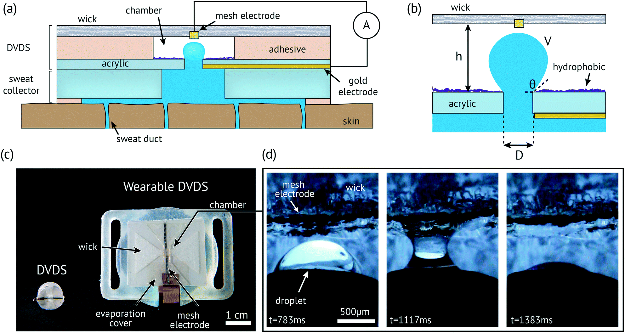 | ||
| Fig. 1 The DVDS flow sensor: a) a side view of the DVDS coupled to a wearable sweat collector; b) close-up of the chamber including critical parameters; c) photo of two different devices including a miniature version (left) and wearable version (right); d) demonstration of droplet breaking onto the mesh electrode. | ||
DVDS: design and theory
The DVDS operates by (1) the fluid entering the chamber through a small hole from the outlet of a pressure-driven channel; (2) forming a capillary bridge that provides electrical conductivity between two electrodes; (3) a strong wicking event that breaks the capillary bridge and resets the process. The chamber and the inlet hole can be coated with a super hydrophobic surface, which causes the droplet to form a spherical cap or partially spherical shape in the chamber, as illustrated in Fig. 1a and the close-up of the chamber in Fig. 1b. Fig. 1c shows a photo of two constructed and tested devices: a small stand-alone version that is only ∼1 cm in diameter (left) and one that has been integrated into a wearable device (right). Fig. 1d shows the droplet breaking onto the mesh electrode and Rayon wick. We demonstrated devices both with and without superhydrophobic coatings, and found superhydrophobic coatings to be the most reliable in operation and were therefore used for data collection in this paper. The video (see the ESI†) and Fig. S1 show a droplet that is nearly spherical when a super hydrophobic coating is used.In Fig. 1b, the chamber height (h) is made by layers of double-sided adhesive and PET films (see the Fabrication section for details). The chamber height controls the volume of the droplet (V). The volume could easily be reduced if photolithography or an injection molding process is employed. The diameter of the inlet (D) is a flexible parameter, but a smaller D encourages the droplet meniscus bridge to break near the inlet, thus allowing h and V to remain small.21 The only other constraint is that D must be smaller than the outlet of the adjacent channel so that the bottom electrode remains in constant electrical contact with the fluid.
The electrode at the top of the wick only makes contact when the droplet reaches a particular volume. A small voltage (0.5 V) is applied to the electrodes and the current is measured over time. The droplets short the electrodes resulting in a brief current spike of several μA and 50–500 ms duration, as shown in Fig. 2a and b. The flow rate is calculated given the known volume: flow rate = volume/T, where the period (T) is the time between the spikes. As the droplet emerges in the channel, an effective contact angle (θ) of the droplet with the substrate plane right before the droplet breaks onto a wick. A perfect sphere is never reached before a capillary bridge is formed, and the volume of each droplet can be calculated,22viz.
 | (1) |
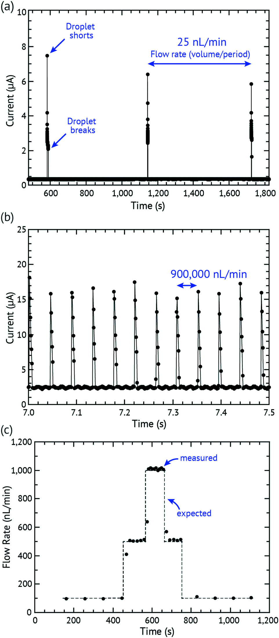 | ||
| Fig. 2 Demonstration of measured droplets: a) 25 nL min−1 with current spikes of a long period; b) 900000 nL min−1 with current spikes of a short period; c) demonstration of expected vs. measured flow rates. | ||
However, the theoretical volume calculated in Table 2 used the spherical equation (where r = h/2) which was in better agreement with the actual volume recorded. For small thicknesses, the theoretical volume deviated from the average volume (46.8 vs. 128 nL, respectively). For thicknesses larger than 447 μm, the theoretical volume closely matched the average experimental volume. We believe that the deviation from the spherical volume is due to the meniscus break of the water droplet extending into the channel, (i.e. fluid pulled out of the DVDS outlet beneath the droplet) which could be corrected by reducing D.
| Thickness (μm) | Theoretical volume of a sphere (nL) | Actual volume (nL) | Std dev of the calibrated device (nL) |
|---|---|---|---|
| 447 | 46.8 | 128 | 4.88 |
| 664 | 153 | 193 | 5.18 |
| 951 | 450 | 491 | 8.82 |
| 1168 | 834.3 | 872.8 | 23.53 |
The droplet in the DVDS is not easily dislodged due to its small volume (10–100s of nL) and high surface tension. The calculated Bond number is 0.057 for the largest well layer we tested (h = 1168 μm). Therefore, in this system, surface tension is a dominant factor over gravity. Because the subjects move a minimal amount, this is fine for in vivo testing; however, body movements can cause accelerations many times gravity (g).23 To account for this and keep the Bond number less than 1, the highest h should be 2400 μm at 5g and 1600 μm to account for 10g acceleration.
The height of the chamber (see Fig. 1b) can be adjusted to allow for different droplet volumes that will change the droplet frequency for larger or smaller flow rates. A positive Laplace pressure (Δp = 2γ/r) is required to create this droplet, and for an input diameter of D = 790 μm and for water (γ = 73 mN/m), the maximum pressure required for operation is a spherical cap with a radius of 395 μm and a pressure of ∼370 Pa. For any case of inflating the droplet beyond a spherical cap, the effective droplet radius only increases, and therefore the spherical cap represents the maximum required input pressure.
Fabrication
The DVDS fabrication starts with an acrylic sheet (1.5 mm thick) laser-cut into a rectangle (25 × 29 mm) with a 0.79 mm diameter hole in the center. The channel that couples to the DVDS must have a diameter larger than 0.79 mm so that the fluid can be in contact with the bottom electrode (see Fig. 1a). The bottom electrode is a 50 nm gold film sputtered onto the bottom of the DVDS substrate. Afterwards, a super hydrophobic coating (Rust-Oleum NeverWet®) was spray-applied onto the top of the acrylic sheet through a shadow mask to only coat the chamber area (3 mm diameter hole). NeverWet® was applied by spraying two coats of the base coat with 30 minutes between coats, and after 30 minutes, spraying three coats of the top coat with a few minute intervals according to the manufacturer's instructions for the product. It was allowed to dry for at least 30 minutes before testing. The contact angle is between 160–175° according to the manufacturer which classifies it as a superhydrophobic surface. It is important to note that the droplet never reaches this high of an angle before it breaks onto the wick, but the hydrophobicity helps maintain better droplet consistency. The chamber consists of laminated sheets of 5 mil (0.127 mm) PET, 3M 1522 adhesive (0.16 mm), and the 3M 9965 microfluidic tape (0.09 mm). In each layer, a hole 3 mm in diameter is laser-cut in the thin laminated sheets (1522 adhesive, PET, 9965 microfluidic tape). The laminated sheets were stuck to the substrate e.g.: acrylic/1522/PET/9965. Different height (h) could be constructed by stacking additional film/tape on top or removing layers in different configurations to get the desired thickness. The only requirement is that the top of the chamber must have adhesive such that an electrode and a wicking layer of Rayon could be placed on top of the stack. Afterwards, a layer of PET is placed on top of that to prevent unwanted evaporation over the chamber.We experimented with several different types of electrode materials for the top electrode including a wire mesh (Ni-plated nylon), a thin tungsten wire, and gold-coated Rayon. We found that the droplet broke very quickly (<10 ms) using either the gold-coated Rayon or thin tungsten wire. For our application, we elected to use the Ni mesh electrode which caused the droplets to break in 50–500 ms which was easy to detect at a lower sampling rate. The electrode (0.8 mm × 25 mm) was laser-cut from woven conductive fabric (200 × 200 × 0.08 mm copper and nickel plated nylon; Adafruit) and was placed on top of the 9965 adhesive such that the electrode passed through the hole to make contact with the droplet. With the mesh electrode in particular, we noted that the first droplet typically takes longer than normal (sometimes seconds) to break, but as soon as it wets, a water film forms within the mesh (which is visible in Fig. 1d and more prominent in the ESI† videos) and subsequent droplets break as expected under 500 ms.
For the on-body device, the DVDS device was placed into a 3-d printed sweat collector (Formlabs Form II 3d printer and clear FLGPCL04 photopolymer resin). Data from tests were run through a Mathematica script to find the peaks and time of each droplet. The dimensions for this on-body device are provided in the ESI.†
In vitro validation
The in vitro testing set-up used a 1 mL Hamilton™ 1000 series Gastight™ syringe connected to a dispensing needle that is attached directly to the hole of the sweat collector and to the DVDS. The syringe pump was a model 110 from KD Scientific. The sampling software was Gamry Reference 600 Potentiostat/Galvanostat/ZRA.The syringe contained 50 mM NaCl and was controlled using a syringe pump. A voltage (0.5 V) was applied and measured with chronoamperometry using the Gamry connection to the electrodes. The pump was set at various flow rates and examples of the output are shown in Fig. 2 and 3. Fig. 2a plots the lowest successful flow rate at 25 nL min−1 with each droplet shorting every 10 minutes (device parameters: volume = 226 nL; h = 0.664 mm; D = 0.79 mm, see Fig. 1b). Lower rates were attempted, but these failed due to the wick drying out. We believe that even lower flow rates could easily be overcome by reducing h and D and preventing evaporation using a larger evaporation cover. Photolithography or other more precise fabrication techniques could also reduce h but was out of the intended scope of this study. Fig. 2b shows a device tested at 900000 nL min−1 showing 12 discrete droplets detected in 0.5 seconds (device parameters: volume = 632 nL; h = 1.168 mm; D = 0.79 mm). At high rates, the device works until the wick fails to remove liquid from the chamber, thus flooding the chamber. Faster rates could potentially be achieved by increasing h to reduce the droplet frequency and by using improved materials that support higher wicking pressures and flow rates.
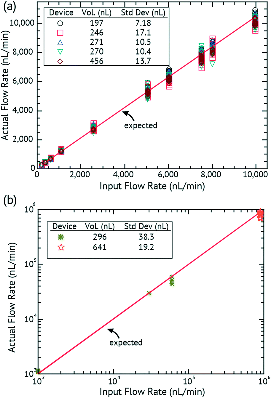 | ||
| Fig. 3
In vitro validation of the input flow rate to the measured flow rate of the DVDS: (a) low flow rates of 100–10000 nL min−1; (b) high flow rates of 1000–900000 nL min−1. | ||
Our lamination-based fabrication method resulted in slight variations in h that affect the volume of the droplet. Droplet volumes from device to device can vary as much as several hundred nL due to small changes in chamber height (h) introduced by manual fabrication. Therefore in this work, every device required calibration prior to use. In the calibration set-up, a syringe pump runs through a series of flow rates (e.g. 100, 500, 1000, 500, and 100 nL min−1) ensuring that at least 5 droplets are detected at each flow rate. The period and flow rate are then used to determine the volume of the droplet. Fig. 2c plots the expected versus measured flow rates in a calibration. Different well layer thicknesses were built and tested and the results are summarized in Table 2. Once a device is calibrated and the volume of the droplet determined for that device, the volume is extremely reliable and repeatable (with standard deviation of droplet volumes between 4.89 and 23.53 nL) over the lifetime of the device. It is certainly possible to imagine a calibration-free device where device tolerances are tightly controlled and thus the device is calibrated only at the factory.
In order to test the range and accuracy, devices were run at intervals from 100 to 900000 nL min−1. Fig. 3 plots the input flow rate of a syringe pump versus the actual flow rate as measured by the DVDS. In Fig. 3a, five separate devices were used in the experiments for flow rates of 100 to 10000 nL min−1. Each flow rate has at least 5 data points collected. Every device is calibrated before the experiment to determine the volume of the droplet. The insets show the volume for each device (based on the calibration) and that volume is used to calculate the flow rate from the measured period. The standard deviation for each device is shown as the error of the droplet volume for the entire experiment set with a very low SD ≤ 17.1 nL. Small changes in the droplet volume can result in significant changes in the flow rate (e.g. at 8000 nL min−1, we expect a droplet every ∼1845 ms, but droplet volume changes range ±200 ms). But the droplet consistency allows excellent accuracy over the range.
Fig. 3b shows two devices performing at higher flow rates from 1000 to 900000 nL min−1. Even at high flow rates, the results show that the DVDS has higher accuracy that follows the expected rate throughout the entire range.
A device was run at steps of 1000, 30000, and 60000 nL min−1. Each flow rate had at least 15 data points collected. The calibrated droplet size was 296 nL with a SD = 38.3 nL. A different device was run at 900000 nL min−1 for 15 seconds, acquiring about 300 data points. The calibrated droplet size was 641 nL and the average volume over this test was 669 nL with a SD = 19.2 nL. The droplet volume remained remarkably consistent considering the extremely high flow rate, averaging 861000 nL min−1 with a standard deviation of the flow rate equal to 24900 nL min−1.
To determine the effect of gravity on the volume of the droplet, calibration tests were performed with the syringe horizontal and then vertical for the thickest well layer (1168 μm) (see Fig. S3†). The average volumes calculated for the droplet were different by less than 10 nL. As a result, we concluded that the orientation and gravity have little to no effect on the volume of the droplet. This can be expected because of the low Bond number of the droplet.
Finally, to test the longevity of the device, the pump was run (device parameters: volume = 190 nL; h = 0.664 mm; D = 0.79 mm) continuously at 100 nL min−1 with daily calibration tests until the device failed. After 200 hours, there was no longer an electrical signal detected. The device failed when salt crystallized onto the wick and into the chamber that eventually impeded droplet formation and breaking. When the device was taken apart, there was visible crystallization on the bottom and sides of the chamber and on the wick (see Table S1†). One could image a device constructed with a 1 mL wick and sealed to prevent evaporation that could potentially last for 10000 hrs at 100 nL min−1.
In vivo validation
Human subject testing was performed under the guidance of the University of Cincinnati's Human Research Protection Program (ID# 2016-4386 approved by the UC Institutional Review Board). All human subjects provided informed consent. The DVDS was coupled to the outlet of a 3D printed sweat collection device using 3M 1522 tape and calibrated using the standard (in vitro) calibration protocol. The device chamber height (h) was fabricated based on the expected sweat rate of the subject: heavy sweating (device: volume = 475 nL; h = 0.951 mm) or light sweating (device: volume = 221 nL; h = 0.664 mm). The sweat collection device was strapped to the dominant forearm using elastic bands and 1522 tape. The collection area covers 2.2698 cm2 of skin. Each DVDS was calibrated before and after experimentation, as shown in Fig. 4. As calculated previously, the DVDS requires input pressures of 100s of Pa, so a logical question is whether sweat generation can provide such pressure. Sweat generation is powered by osmotic pressures of 1s to 10s of kPa, easily satisfying this device requirements.24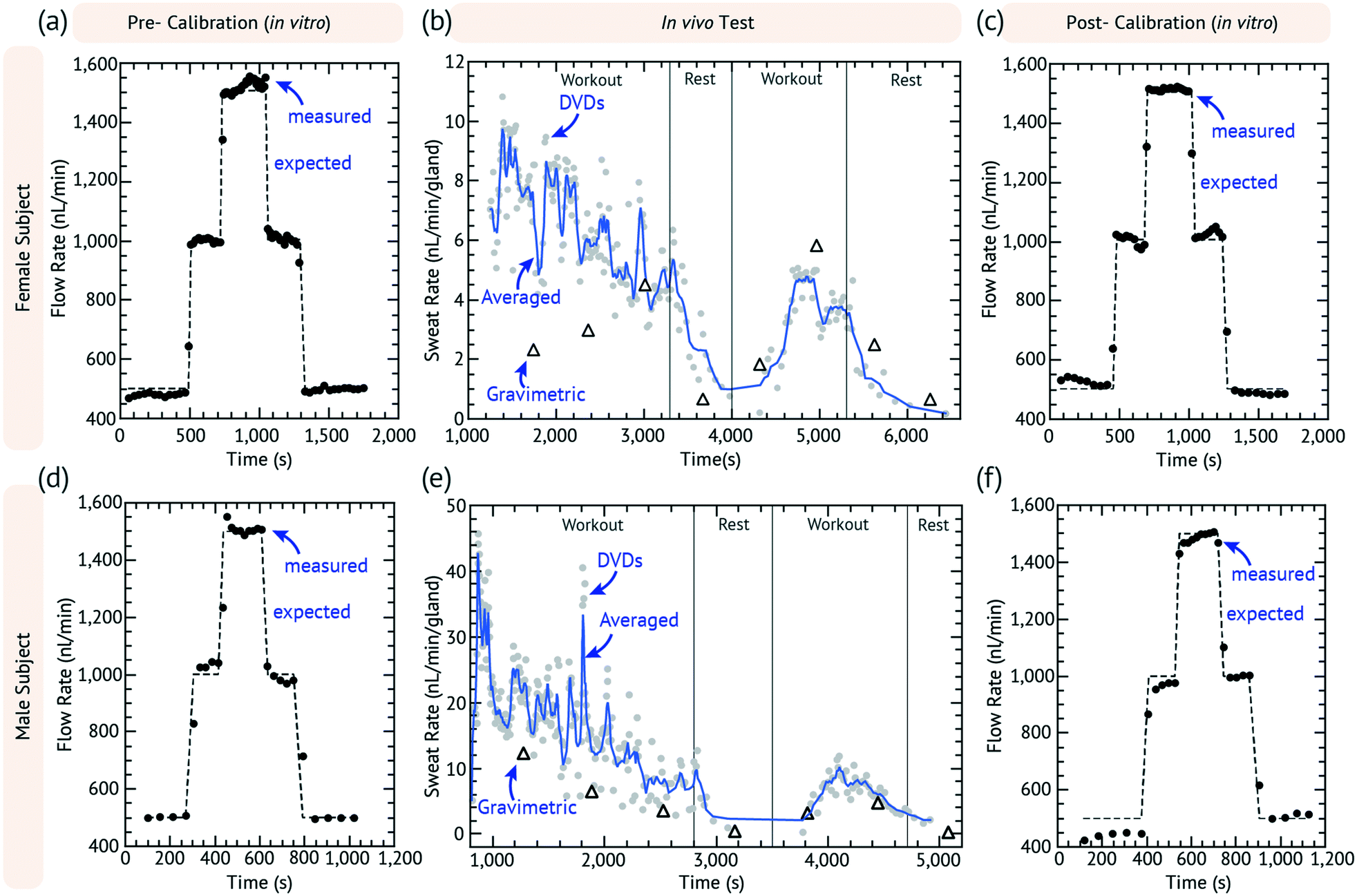 | ||
| Fig. 4 Exercise sweat test for a female subject (a–c) and male subject (d–f). Pre-calibrations (a and d) and post calibrations (c and f) to validate the device showing the expected (dashed) and measured (solid dots) data. For on-body testing (b and e for female and male, respectively), DVDS (gray circles) and gravimetric data (white triangles) are shown. The moving average of the DVDS data is also shown (blue line). | ||
During in vivo testing, gravimetric samples were also collected and measured, using pre-weighed 1.06 cm diameter laser-cut TechniCloth™ nonwoven wipe (TX609, Texwipe, Kernersville, NC) disks. The disks were strapped to the subject's arm using an acrylic holder following similar previous protocols.24
The subjects were asked to work out on an exercise bike at a moderate rate. Each device had a dead volume of the DVDS and sweat collector of 2.9 and 25.6 mm3, respectively, which in total took about 15 to 20 min to fill depending on how fast the subject began sweating. The gravimetric measurements began as soon as the DVDS detected the first droplet. Each gravimetric sample is collected for 10 min and then immediately weighed. The subject exercises at the same rate for 30 min and three gravimetric measurements are taken while the DVDS measurements are continuously collected. The subject then takes a 10 minute rest with one parallel gravimetric measurement. The subject is asked to begin exercising again for 20 minutes with two more gravimetric measurements during that time. The subject then stops exercising and a final gravimetric measurement is taken. The DVDS and sweat collection device is then calibrated a second time after it is removed from the subject by connecting it to a syringe pump as described above. The chronoamperometry data from this test is run through the script that finds each current peak and calculates the time differences between each peak. The calibration data is used to calculate the volumetric flow rate of the in vivo data, which are the plots shown in Fig. 4.
Discussion
Fig. 4(a–c) and (d–f) show the results of an exercise test of a female and male subject, respectively. The results of other tests are shown in Fig. S2.†Fig. 4a and d show the pre-calibration data and Fig. 4c and f show the post-work out calibration. Fig. 4b and e plot the raw DVDS data, the moving average, and the gravimetric results for every 10 min. The in vivo experiments had more variation than the in vitro syringe pump experiments, but the pre- and post-calibration data confirmed that the device was working as expected. The subjects had normal arm movement during the workout and they were occasionally asked to flex their muscles or move their arm to see if there were any motion effects or if the droplet could be dislodged, and none were directly observed. Occasionally during a gravimetric change, we would observe changes in rate, but these were not always consistent. This could be due to pressure changes affecting the wearable device.The sweat rate was calculated by gland density, considering that the average gland density is 100 glands per cm2 for the forearm (i.e. ∼226 glands).26 In Fig. 4b, the female subject started with a sweat rate of ∼10 nL min−1 per gland which decreased steadily to ∼5 nL min−1 per gland in the first workout period. The sweat response was delayed such that the lowest rate for the female subject was achieved nearly 1000 s after the rest period. The rate peaked at 5 nL min−1 per gland almost 800 s after the start of the second workout.
In Fig. 4e, the male subject had a high rate at about 45 nL min−1 per gland, which then steeply dropped after several minutes to ∼20 nL min−1 per gland. The sweat rate quickly dropped to zero in 200 s after the start of the rest period, which was must faster than that of the female subject. After the rest period, the flow rate peaked at 10 nL min−1 per gland about 600 s into the second workout. The initial measured rate for the male subject is unexpectedly high.25
We speculate that air bubble formation in the sweat collector device could be causing the unexpected results during the initial phases of in vivo device use. When the device is first placed onto the skin, undoubtedly, air gaps and pockets exist, which can be pushed forward as sweat is generated. Such air bubbles could cause false high-readings of sweat generation rate (e.g. partial droplets) and could cause erratic changes in the measured sweat generation rate as they pass through the system. We therefore believe that the later data with reduced noise in the second workout represents the most accurately normal operation of the device, especially since the pre- and post-calibration data are well matched. In addition, since the DVDS has rectifying ability, there cannot be backwards flow into the device resulting from the arm movement. However, some of the variation in the flow rate may be due to body movement or other physiological factors that we have not yet considered here.
Certain design considerations of the DVDS can improve its performance depending on the intended application. Lower flow rates could be achieved if the chamber is designed for smaller droplet volumes. One major challenge for smaller flow rates was the wick drying out, which causes a longer breaking time and changes the volume of the droplet. In this case, it may make more sense to use a more hydrophilic electrode or to gold-coat the Rayon to decrease the droplet break time. Also, as mentioned previously, more sophisticated methods for device construction would have an impact on factory calibration potentially improving the range of flow rates that could be detected.
The lifetime of the device depends entirely on the management of the fluid. Since this particular design intended to evaporate the water so as not to oversaturate and potentially flood the chamber, the major problem was the salt build-up in the wick, eventually building up into the chamber. The effective management of fluid requires a balance of keeping the active site wet (in the case of the mesh electrode), and directing enough fluid away so that salt does not precipitate and clog the chamber. Such design considerations require foreknowledge of the flow rate range, droplet volume, and evaporation rate; however, simple efforts to prevent evaporation or increasing the reservoir wick volume may improve the lifetime from weeks to months.
Conflicts of interest
Jason Heikenfeld has an equity interest in Eccrine Systems, Inc., a company that may potentially benefit from the research results, and also serves on the company's Board. The terms of this arrangement have been reviewed and approved by the University of Cincinnati in accordance with its conflict of interest policies.Acknowledgements
Funding was made possible by the Ohio Federal Research Network through the Ohio Department of Higher Education (ODHE) and Wright State Applied Research Corporation (#WSARC-1077-700), the Air Force Research Labs Award #FA8650-15-C-6625, and the NSF EPDT Award #1608275. The authors would also like to thank Eccrine Systems Inc. particularly Mikel Larson and Dr. Michelle Hoffman for recommending flow tests in Fig. 3 and good conversations on device fabrication optimized for sweat rate monitoring.Notes and references
- J. L. Atkins and P. E. M. Butler, Hyperhidrosis: A Review of Current Management, Plast. Reconstr. Surg., 2002, 110, 222–228 CrossRef.
- D. J. Brake and G. P. Bates, Fluid losses and hydration status of industrial workers under thermal stress working extended shifts, Occup. Environ. Med., 2003, 60, 90–96 CrossRef CAS.
- M. Jia, W. M. Chew, Y. Feinstein, P. Skeath and E. M. Sternberg, Quantification of cortisol in human eccrine sweat by liquid chromatography - tandem mass spectrometry, Analyst, 2016, 141, 2053–2060 RSC.
- A. Jajack, M. Brothers, G. Kasting and J. Heikenfeld, Enhancing glucose flux into sweat by increasing paracellular permeability of the sweat gland, PLoS One, 2018, 13, e0200009 CrossRef PubMed.
- J. Heikenfeld, et al. Wearable sensors: modalities, challenges, and prospects, Lab Chip, 2018, 18, 217–248 RSC.
- V. Lien and F. Vollmer, Microfluidic flow rate detection based on integrated optical fiber cantilever, Lab Chip, 2007, 7, 1352 RSC.
- Y. Temiz and E. Delamarche, Sub-nanoliter, real-time flow monitoring in microfluidic chips using a portable device and smartphone, Sci. Rep., 2018, 8, 10603 CrossRef PubMed.
- H. Y. Y. Nyein, et al. A Wearable Microfluidic Sensing Patch for Dynamic Sweat Secretion Analysis, ACS Sens., 2018, 3, 944–952 CrossRef CAS PubMed.
- VVP Technology – Dynamic Devices. Available at: http://dynamicdevices.com/vvp-technology/, (Accessed: 10th August 2018).
- PTFE Liquid Flow Sensors. Available at: https://www.omega.com/pptst/FPR1500.html#description, (Accessed: 10th August 2018).
- LPG10 - Liquid Flow Sensor| Sensirion. Available at: https://www.sensirion.com/en/flow-sensors/liquid-flow-meters/page/lpg10-planar-miniature-flow-sensors/, (Accessed: 10th August 2018).
- SLG - Liquid Flow Meter | Sensirion. Available at: https://www.sensirion.com/en/flow-sensors/liquid-flow-meters/slx-standalone-liquid-flow-meters/uhplc-liquid-flow-sensors-for-ultra-low-flow-rates/, (Accessed: 10th August 2018).
- Liquid Flow Meters - Rheotherm. Available at: https://intekflow.com/flow-measurement-instruments/low-flow-meters-liquid/, (Accessed: 10th August 2018).
- A. Koh, et al. A soft, wearable microfluidic device for the capture, storage, and colorimetric sensing of sweat, Sci. Transl. Med., 2016, 8, 366ra165 CrossRef PubMed.
- J. A. Rogers, et al. A fluorometric skin-interfaced microfluidic device and smartphone imaging module for in situ quantitative analysis of sweat chemistry, Lab Chip, 2018, 18, 2178 RSC.
- J. K. Sim, S. Yoon and Y.-H. Cho, Wearable Sweat Rate Sensors for Human Thermal Comfort Monitoring, Sci. Rep., 2018, 8, 1181 CrossRef.
- P. Salvo, et al. A Wearable Sensor for Measuring Sweat Rate, IEEE Sens. J., 2010, 10, 1557–1558 Search PubMed.
- T. Glennon, et al. ‘SWEATCH’: A Wearable Platform for Harvesting and Analysing Sweat Sodium Content, Electroanalysis, 2016, 28, 1283–1289 CrossRef CAS.
- A. Koh, et al. A soft, wearable microfluidic device for the capture, storage, and colorimetric sensing of sweat, Sci. Transl. Med., 2016, 8, 366ra165 CrossRef.
- Y. Yang, et al. Wearable microfluidics: fabric-based digital droplet flowmetry for perspiration analysis, Lab Chip, 2017, 17, 926–935 RSC.
- S. Barkley, S. J. Scarfe, E. R. Weeks and K. Dalnoki-Veress, Predicting the size of droplets produced through Laplace pressure induced snap-off, Soft Matter, 2016, 12, 7398–7404 RSC.
- D. Wu, et al. Determination of contact angle of droplet on convex and concave spherical surfaces, Chem. Phys., 2015, 457, 63–69 CrossRef CAS.
- D. Kimm and D. V. Thiel, Hand Speed Measurements in Boxing, Procedia Eng., 2015, 112, 502–506 CrossRef.
- Z. Sonner, et al. The microfluidics of the eccrine sweat gland, including biomarker partitioning, transport, and biosensing implications, Biomicrofluidics, 2015, 9, 031301 CrossRef CAS PubMed.
- P. Simmers, S. K. Li, G. Kasting and J. Heikenfeld, Prolonged and localized sweat stimulation by iontophoretic delivery of the slowly-metabolized cholinergic agent carbachol, J. Dermatol. Sci., 2018, 89, 40–51 CrossRef CAS.
- K. Sato, W. H. Kang, K. Saga and K. T. Sato, Biology of sweat glands and their disorders. I. Normal sweat gland function, J. Am. Acad. Dermatol., 1989, 20, 537–563 CrossRef CAS.
Footnote |
| † Electronic supplementary information (ESI) available. See DOI: 10.1039/c8lc00968f |
| This journal is © The Royal Society of Chemistry 2019 |