 Open Access Article
Towards stable and efficient electrolytes for room-temperature rechargeable calcium batteries†
Zhenyou
Li
 a,
Olaf
Fuhr
 bc,
Maximilian
Fichtner
 ab and
Zhirong
Zhao-Karger
 *a
*a
aHelmholtz Institute Ulm (HIU) Electrochemical Energy Storage, Helmholtzstraße 11, D-89081 Ulm, Germany. E-mail: zhirong.zhao-karger@kit.edu
bInstitute of Nanotechnology (INT), Karlsruhe Institute of Technology (KIT), Hermann-von-Helmholtz-Platz 1, D-76344 Eggenstein-Leopoldshafen, Germany
cKarlsruhe Nano Micro Facility (KNMF), Karlsruhe Institute of Technology (KIT), Hermann-von-Helmholtz-Platz 1, D-76344 Eggenstein-Leopoldshafen, Germany
First published on 16th August 2019
Abstract
Rechargeable calcium (Ca) batteries have the prospect of high-energy and low-cost. However, the development of Ca batteries is hindered due to the lack of efficient electrolytes. Herein, we report novel calcium tetrakis(hexafluoroisopropyloxy)borate Ca[B(hfip)4]2 based electrolytes exhibiting reversible Ca deposition at room temperature, a high oxidative stability up to 4.5 V and high ionic conductivity >8 mS cm−1. This finding opens a new approach towards room-temperature rechargeable calcium batteries.
Broader contextThe development of efficient and cost-effective energy storage technologies is of prime importance for implementing clean and renewable energies to meet the world's increasing energy demands and emissions reduction targets. Rechargeable batteries are regarded as the most feasible solution for these storage applications. However, the rapidly growing global market of electric vehicles (EVs) and grid electricity storage has raised concerns about safety, cost and sustainability of the present lithium-ion batteries (LIBs). Battery systems based on multivalent metals such as magnesium (Mg) and calcium (Ca) have attracted substantial interest as one of the most promising next-generation technologies. A key challenge in the realization of rechargeable Ca batteries is the development of a practical electrolyte for efficient Ca deposition. In this work, we present a novel electrolyte with a wide electrochemical window and good chemical stability, which may pave the way for high-energy Ca batteries. |
The wide-scale adoption of emission-free transportation and renewable energy decisively depends on efficient and cost-effective energy storage systems. The current lithium-ion battery (LIB) technology is not able to meet the energy demands for extended driving range for electric vehicles (EVs) and grid-scale electricity storage. Additionally, the rapid growth of the global battery market is raising critical concerns about the mid- and long-term availability of certain raw materials such as cobalt (Co), nickel (Ni) and lithium (Li), which are essential components in commercial LIBs.1 Development of multivalent battery technologies based on elements that are more abundant is considered to be a promising option to achieve improved energy densities and at the same time significantly reduced cost. Multivalent ions are capable of transferring double or triple electrons per ion, thus offering the promise of a two- or three-fold increase in the capacity as compared to the monovalent Li-ion and Na-ion batteries. Moreover, in contrast to Li or Na metal, the potential feasibility of the use of multivalent metallic e.g. magnesium (Mg) and calcium (Ca) anodes could result in a significant increase in the energy densities of the battery systems.
Ca is the fifth most abundant element in the earth's crust with equal geographical resource distribution and has the advantages of safety, nontoxicity and low cost. Ca has a high volumetric capacity of 2073 mA h cm−3 and a reduction potential of −2.87 V vs. standard hydrogen electrode (SHE), which is close to that of Li (−3.04 V vs. SHE) and 0.5 V lower than that of Mg (−2.37 V vs. SHE). Thus, the cell voltage and energy density of Ca batteries is potentially comparable with the LIBs, and yet higher than Mg batteries. In addition, the Ca2+ ion exhibits a larger radius (1.12 Å) than the Mg2+ ion (0.72 Å) while carrying the same charge,2 which may allow faster Ca2+ ion diffusion in the cathodes due to the greater softness of the ion. Hence, rechargeable Ca batteries can be regarded as one of the most attractive candidates for post-lithium-ion battery technologies.3,4 However, in contrast to the extensive research on Mg batteries, the development of Ca batteries is impeded by the lack of suitable electrolytes.
One of the fundamental problems identified in the early study of non-aqueous Ca electrolytes is the incompatibility of the Ca metal with the conventional salts in aprotic solvents due to the formation of passivation surface films preventing Ca–ion transport.5–7 The concepts of using Grignard reagents for reversible Mg plating/stripping cannot be analogously adapted to Ca electrolytes.3 The pioneering work of reversible Ca deposition was demonstrated with the solution of calcium tetrafluoroborate Ca(BF4)2 in ethylene carbonate (EC): propylene carbonate (PC), but only at elevated temperature (>75 °C).8 In addition, it was revealed that Ca plating/stripping in Ca(BF4)2 solutions was accompanied by deleterious side-reactions, forming a considerable amount of CaF2 on the Ca electrode.8 Recently calcium borohydride Ca(BH4)2 in tetrahydrofuran (THF) was reported to be capable of reversible Ca deposition at room temperature.9 However, metal borohydrides are known as a class of strong reducing agents implying their intrinsic instability towards oxidation.10 Therefore, rational design of ion-conductive Ca compounds is of paramount importance to develop an electrolyte, which is capable of plating and stripping Ca at room temperature, but also has the essential properties including compatibility with the metallic Ca anode, a wide electrochemical window and efficient ion transport. In general, an anion that lacks donor atoms with electron lone pairs for metal cation coordination leads to more favored ion association and higher cation mobility. Moreover, the chemical bonding in anions is the main factor that determines the anodic stability of an electrolyte. The anion oxidation stability can be predicted from theoretical calculations e.g. the lower the HOMO energy level of the anion, the greater oxidative stability can be expected.11 The fluorinated alkoxyaluminate and alkoxyborate anions such as [B(hfip)4]− or [Al(hfip)4]− (hfip = –OCH(CF3)2) have been proven to be promising candidates for the formulation of salts with high ionic conductivity and high anodic stability.12–14 Owing to the high electronegativity of the fluorine atom, the charge in bulky alkoxyaluminate and alkoxyborate anions is extensively delocalized resulting in weak cation–anion interactions and thus a high ionic conductivty.15 Moreover, the stable C–F bonds account for the high electrochemical stability (for example, Li[Al(hfip)4] exhibits a high anodic stability >5.0 V vs. Li/Li+).12 Considering the double charged Mg- or Ca-ion, their salts comprising such weak coordinating anions can be especially desirable to achieve high ion mobility in the electrolytes. Indeed, we have successfully synthesized the magnesium tetrakis(hexafluoroisopropyloxy) borate Mg[B(hfip)4]2 and demonstrated its superior properties for use as a practical and efficient electrolyte for potential high-energy Mg batteries.13,14
Inspired by the promising results in Mg electrolytes, calcium tetrakis(hexafluoroisopropyloxy)borate Ca[B(hfip)4]2 was proposed as a potential electrolyte for room-temperature rechargeable Ca batteries.
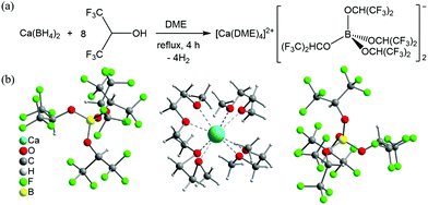
Ca[B(hfip)4]2 was synthesized via a clean and straightforward route by reacting Ca(BH4)2 with hexafluoroisopropanol in dimethoxy ethane (DME), as shown in Fig. 1a. It is worth noting that various Ca salts can be synthesized by this type of reaction using different fluorinated alkylalcohols similar to as reported using Mg analogue compounds.13 In this work, we representatively studied Ca[B(hfip)4]2 for use as a Ca electrolyte. The pure solid product Ca[B(hfip)4]2·4DME was readily isolated after removal of the solvent by vacuum after completion of the reaction, which was characterized using nuclear magnetic resonance (NMR) and mass spectroscopy (MS). Preparation and characterization details are provided in the ESI.† The single crystals could be isolated from the unstirred concentrated DME solutions stored in an argon-filled glovebox at ambient temperature for a week. The crystal structure has been determined using X-ray crystallography and confirmed as Ca[B(hfip)4]2·4DME (Fig. 1b). The crystal unit consists of typical ionic pairs, in which the counter anion [B(hfip)4]− with the center boron (B) atom is bonded with four hexafluoroisopropyloxy groups with a tetrahedral geometry. The Ca2+ ion is solvated with four DME molecules exhibiting a slightly distorted square antiprismatic coordination geometry. Due to the larger size of the Ca2+ ion compared to the Mg2+ ion, the solvated Ca2+ ion exhibits eight-coordination with an average O–Ca bonding length of approximately 2.43 Å, which is longer than that of the O–Mg bonds of Mg[B(hfip)4]2·3DME (2.06 Å). These results indicate that the desolvation energy of the solvated Ca2+ ion can be assumed to be lower than that of the solvated Mg2+ ion, which is beneficial for Ca2+ ion intercalation into a solid electrode.
Owing to the stable B–O bonds in the [B(OCH(CF3)2)4]− anion,15,16 Ca[B(hfip)4]2·4DME, similar to the magnesium analogue,13 has also been proven to be air and water insensitive by means of NMR (Fig. S1, ESI†), which is of great advantage for practical applications. The thermal stability of Ca[B(hfip)4]2·4DME was examined by means of simultaneous thermogravimetric analysis-differential scanning calorimetry-mass spectroscopy (TGA-DSC-MS) (Fig. S2, ESI†). The DSC profile reveals that the Ca salt melts at 57 °C and partial DME is released at 97 °C as indicated from the endothermal peak of DSC and simultaneous MS signals. At approximately 120 °C, the compound starts to release most of the DME and is decomposed at the same time. These data confirm that the Ca salt is thermally stable up to 120 °C.
The Ca electrolyte with desired concentration can be prepared by dissolving the Ca[B(hfip)4]2·4DME salt into a proper amount of chosen solvent. In this work, we used DME solvent to prepare the electrolyte solution (denoted as CaBhfip/DME) for the study of its electrochemistry.
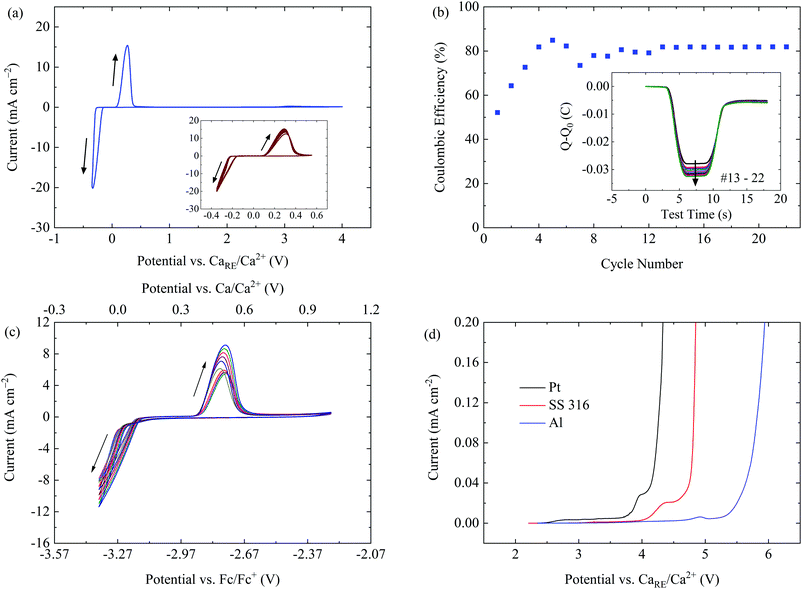
Electrochemical plating and stripping of Ca in a 0.25 M CaBhfip/DME electrolyte was first investigated by cyclic voltammetry (CV) at a scan rate of 80 mV s−1 in a three-electrode cell, using Pt as the working electrode (WE) and Ca as a reference electrode (RE) and a counter electrode (CE), respectively. The first CV scan displays the reductive current associated with Ca deposition starting at −0.30 V while the oxidation current onset for Ca dissolution is at 0.22 V (Fig. S3, ESI†). The native passivation film on the counter Ca electrode is due to the high sensitivity of Ca to the atmosphere which could account for the larger polarization and smaller current intensity in the initial cycles. After the conditioning process with 5 CV cycles, the plating/stripping of the electrolyte proceeded with smaller over-potential and improved reversibility. Fig. 2a demonstrates the highly reversible Ca plating/stripping in the electrolyte with a voltage range of −0.35 to 4 V at a scan rate of 80 mV s−1. The over-potential for plating and stripping in the extended CV cycles remained at −0.22 and 0.10 V, respectively. The decreased over-potential and enhanced intensity of the current waves over CV cycles might also be attributed to the initial Ca deposition on the surface of the WE, which facilitates the nucleation of crystalline Ca in the successive cycles.
In addition, the large current response (>20 mA cm−2) at a fast scan rate of 80 mV s−1 indicates an efficient Ca deposition from the CaBhfip/DME electrolyte and implies the high ionic conductivity of the electrolyte. In fact, a conductivity of approximately 8.3 mS cm−1 was measured for the 0.25 M CaBhfip/DME solution by a conductometer at 23 °C, which is on the level of the ordinary Li-ion electrolytes. Moreover, reversible Ca deposition could be achieved at all scan rates ranging from 20 mV s−1 to 100 mV s−1 as shown in Fig. S4 (ESI†), demonstrating an excellent rate capability of the electrolyte.
Based on the charge balance of each CV scan, the coulombic efficiency of Ca deposition was measured. The inset as seen in Fig. 2b indicates that the efficiency increases within the first few cycles and is stabilized at ∼80% in the continuous cycles. The corresponding charge balance curves of each cycle from the 13th to 22nd cycles, presented in the inset of Fig. 2b, confirm the reversible plating/stripping process. This relatively low efficiency might be attributed to the decomposition of the electrolyte and/or to the detachment of the small sized Ca deposits from the WE surface. In fact, some of the Ca deposits were found on the separators after disassembly of the cells. By characterizing the deposits using SEM-EDX (Fig. S5, ESI†), we observed that both morphology and elemental components of the deposits on the separators are identical to that on the WE. More details about the morphology of Ca deposits are provided in the following section.
To verify the suitability and reliability of using metallic Ca as the RE in the CaBhfip/DME electrolyte, the CV measurements with a three-electrode cell configuration using Ag as the RE and ferrocene (Fc) as an internal reference were performed. As shown in Fig. S6 (ESI†), Ca plating/stripping starts at −3.59/−3.04 V vs. Fc/Fc+ in the initial cycle, resulting in an over-potential of 0.55 V, which is in agreement with the data measured with Ca as the RE as shown Fig. S3 (ESI†). The inset in Fig. 2c indicates the improved reversibility and decreased over-potential of 0.35 V over cycling. Taking the theoretical potential difference of Fc/Fc+ and Ca/Ca2+ of 3.27 V into account,17 the potential difference between the two cell configurations is approximately 0.2 V.
The oxidative stability of the CaBhfip/DME electrolyte on conventional current collectors, including stainless steel (SS 316), Pt and Al was examined by linear sweep voltammetry (LSV) using both types of three-electrode cell. Fig. 2d shows the voltammograms using Ca as the RE, indicating an anodic stability of 3.9 V for Pt. Moreover, superior oxidative stabilities up to 4.2 V and 4.8 V were measured when using SS 316 and Al as the WEs, demonstrating that the CaBhfip/DME electrolyte is well suited for conventional current collectors. Remarkably, the anodic stability >4.2 V of the electrolyte on SS and Al electrodes surpasses that of the DME solvent. A similar behavior has been observed with Al in the Li-ion electrolyte, e.g. lithium hexafluorophosphate (LiPF6) in propylene carbonate (PC), where a protection film on the electrode surface formed with some electrolyte components was verified. The reasons for these phenomena in our work will be further investigated. Nevertheless, with the outstanding stability, Ca[B(hfip)4]2 based electrolytes may open the pathway to explore high-voltage cathodes for Ca batteries. In addition, the stability of the Ca(BH4)2/THF electrolyte was measured to be approximately 2.0 V vs. Ca under the same conditions (Fig. S7, ESI†).
The LSVs measured using Fc as the reference show overlapping of the oxidative currents of the electrolyte and ferrocene, which may lead to an inaccurate determination (Fig. S8, ESI†). Nevertheless, these data also indicate the same trend of the anodic stability of the electrolyte on different metals as the results obtained with the three-electrode cells using Ca as the RE.
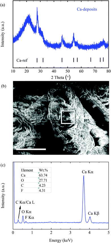
Furthermore, the deposition product was prepared by applying a reductive current of 0.2 mA cm−2 with a cell comprising Pt as the WE and Ca as the CE in 0.25 M electrolyte for 20 h. Interestingly, the as-prepared deposits appeared to be a black powder, which was characterized by means of X-ray diffraction spectroscopy (XRD) and scanning electron microscopy (SEM). As presented in Fig. 3a, all diffraction peaks match well with the Ca reference pattern with PDF No. 00-023-0430, indicating a dominant cubic Ca phase. The broad peaks with a low intensity imply a lower crystallinity and a smaller size of Ca deposits, which remarkably differ from the smooth morphology of Mg deposits obtained from the Mg[B(hfip)4]2 electrolytes. (The signal at around 20° corresponds to the diffraction of silica of the glass capillary).
 | ||
| Fig. 3 Characterization of Ca deposits. (a) The PXRD pattern of Ca deposits. (b) The SEM image of the deposits; the scale bar is 250 μm. (c) The EDX spectrum within the white squared area. | ||
The SEM image of the deposits shows micro-sized agglomerates without obvious crystalline features (Fig. 3b). The energy dispersive X-ray spectroscopy (EDX) spectrum (Fig. 3c) indicates that the deposits are mainly composed of Ca and O with trace amounts of carbon (C) and fluorine (F). Large amounts of O element originated from the short period of air-exposure of the highly reactive fresh Ca deposits before the measurement. The F containing component was most likely derived from the reduction of the electrolyte at a low potential. Similar behaviour was verified in a Li-ion electrolyte e.g. the formation of LiF and PF3 by reduction of LiPF6 electrolytes.18 It is worth mentioning that no chemical change on the Ca surface was observed after a piece of freshly polished Ca metal (99.9%) was soaked in the CaBhfip/DME electrolyte for weeks. According to EDX, the atomic ratio of F/Ca is ∼14%, corresponding to approximately 7% CaF2 in all Ca deposits. A small amount of CaF2 has been proven not to inhibit plating and stripping,9 which was also observed in the CV measurements in this study. The impacts of the CaF2 layer on long-term Ca cycling will be further investigated.
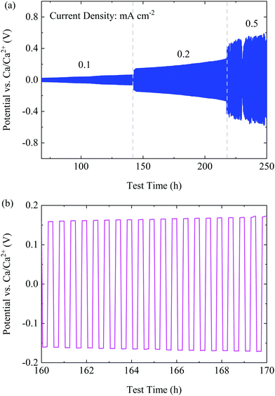
To investigate the cyclability of the CaBhfip/DME electrolyte, symmetric Ca|Ca cells were assembled to carry out the galvanostatic measurements at constant current densities. The galvanostatic cycling at 0.01 mA cm−2 was applied as the conditioning step similar to the CV measurements as discussed before. A large over-potential (400 mV) was observed (Fig. S9, ESI†), which could be caused by the native surface passivation of the Ca electrodes. However, after conditioning, the cell with the CaBhfip/DME electrolyte retains a low polarization of <60 mV and <200 mV at a current density of 0.1 and 0.2 mA cm−2, respectively, as shown Fig. 4a. A typical voltage profile at 0.2 mA cm−2 in Fig. 4b exhibits flat plateaus, suggesting a smooth Ca deposition/dissolution process. With a further increased current density of 0.5 mA cm−2, the over-potential of Ca plating/stripping increased to >500 mV. Nevertheless, the symmetric cell using CaBhfip/DME electrolyte has been operated for more than 250 h, which demonstrates the best cycling stability and rate capability among the reported Ca electrolytes to date.
 | ||
| Fig. 4 (a) The cycling performance of the CaBhfip/DME electrolyte at various current densities. (b) A typical voltage profile at a current density of 0.2 mA cm−2. | ||
Table 1 summarizes the statistical comparison of the new borate based electrolyte with the reported electrolytes to date. It shows that Ca[B(hfip)4]2 has favourable features as an efficient electrolyte at room temperature. The relatively low coulombic efficiency for Ca deposition may be attributed to the formation of the small-sized Ca deposits from the CaBhfip/DME solutions as discussed above. Further improvement will be carried out by modifying the electrolyte composition e.g. solvent, concentration and additive.
| Electrolytic properties | Ca(BF6)2/EC:PC8 | Ca(BH4)2/THF9 | Ca[B(hfip)4]2/DME |
|---|---|---|---|
| Concentration/M | 0.45 | 1.5 | 0.25 |
| Operating temperature/°C | 100 | r.t. | r.t. |
| Anodic stability/V | ∼3.5 (Al) | ∼3.0 (Au) | 3.9 (Pt), >4.5 (Al) |
| Ionic conductivity/mS cm−1 | ∼5.5 (25 °C) | n.a. | ∼8.3 (23 °C) |
| Plating/stripping over-potential/V (CV scan rate/mV S−1) | −0.52/−0.42 (0.5) | −0.25/0.10 (25) | −0.22/0.10 (80) |
| Coulombic efficiency/% | n.a. | 94.8 | 80 |
| Decomposition on Ca metal | CaF2 (>30%) | CaH2 (10%) | CaF2 (∼7%) |
To summarize, we present the feasibility of designing a new class of efficient Ca electrolytes based on the Ca compounds with weakly-coordinating anions. The straightforward synthetic method for formulating new Ca salts by incorporation of various fluorinated alkoxyborates anions will serve as a useful tool for further optimization of the electrolyte properties. The Ca[B(hfip)4]2 electrolytes exhibit state-of-the-art electrochemical properties in terms of high oxidative stability, high ionic conductivity and good capability of long-term reversible Ca cycling. The outstanding properties of the electrolyte pave an avenue towards room temperature high-energy Ca batteries.
Conflicts of interest
The authors declare no competing interests.Acknowledgements
The authors acknowledge the funding from Bundesministerium für Bildung und Forschung (BMBF) of Germany via the “MagSiMal” project (03XP0208). This project has received funding from the European Union's Horizon 2020 research and innovation programme under grant agreement No 824066. This work contributes to the research performed at CELEST (Center for Electrochemical Energy Storage Ulm-Karlsruhe) and was funded by the German Research Foundation (DFG) under Project ID 390874152 (POLiS Cluster of Excellence). The authors thank Marcel Merkel for the PXRD measurement.Notes and references
- C. Vaalma, D. Buchholz, M. Weil and S. Passerini, Nat. Rev. Mater., 2018, 3, 18013 CrossRef
.
- R. Shannon, Acta Crystallogr., Sect. A: Cryst. Phys., Diffr., Theor. Gen. Crystallogr., 1976, 32, 751–767 CrossRef
.
- J. Muldoon, C. B. Bucur and T. Gregory, Chem. Rev., 2014, 114, 11683–11720 CrossRef CAS PubMed
.
- R. J. Gummow, G. Vamvounis, M. B. Kannan and Y. He, Adv. Mater., 2018, 30, 1801702 CrossRef PubMed
.
- K. Xu, Chem. Rev., 2014, 114, 11503–11618 CrossRef CAS PubMed
.
- A. Ponrouch and M. R. Palacin, Curr. Opin. Electrochem., 2018, 9, 1–7 CrossRef CAS
.
- D. Aurbach, R. Skaletsky and Y. Gofer, J. Electrochem. Soc., 1991, 138, 3536–3545 CrossRef CAS
.
- A. Ponrouch, C. Frontera, F. Bardé and M. R. Palacín, Nat. Mater., 2015, 15, 169 CrossRef PubMed
.
- D. Wang, X. Gao, Y. Chen, L. Jin, C. Kuss and P. G. Bruce, Nat. Mater., 2017, 17, 16 CrossRef PubMed
.
- R. Mohtadi, M. Matsui, T. S. Arthur and S. J. Hwang, Angew. Chem., Int. Ed., 2012, 51, 9780–9783 CrossRef CAS PubMed
.
- A. J. Crowe, K. K. Stringham and B. M. Bartlett, ACS Appl. Mater. Interfaces, 2016, 8, 23060–23065 CrossRef CAS PubMed
.
- S. Tsujioka, B. G. Nolan, H. Takase, B. P. Fauber and S. H. Strauss, J. Electrochem. Soc., 2004, 151, A1418–A1423 CrossRef CAS
.
- Z. Zhao-Karger, M. E. Gil Bardaji, O. Fuhr and M. Fichtner, J. Mater. Chem. A, 2017, 5, 10815–10820 RSC
.
- Z. Zhao-Karger, R. Liu, W. Dai, Z. Li, T. Diemant, B. P. Vinayan, C. Bonatto Minella, X. Yu, A. Manthiram, R. J. Behm, M. Ruben and M. Fichtner, ACS Energy Lett., 2018, 3, 2005–2013 CrossRef CAS
.
- I. Krossing and A. Reisinger, Coord. Chem. Rev., 2006, 250, 2721–2744 CrossRef CAS
.
-
Y. R. Luo, Comprehensive Handbook of Chemical Bond Energies, CRC Press, Boca Raton, FL, 2007 Search PubMed
.
- D. S. Tchitchekova, D. Monti, P. Johansson, F. Bardé, A. Randon-Vitanova, M. R. Palacín and A. Ponrouch, J. Electrochem. Soc., 2017, 164, A1384–A1392 CrossRef CAS
.
-
Modern Aspects of Electrochemistry, ed. K. X. R. T. Jow, O. Borodin and M. Ue, Springer-Verlag, New York, 2014, vol. 58, p. XVIII, 476 Search PubMed
.
Footnote |
| † Electronic supplementary information (ESI) available: Full Experimental section and additional data are provided. CCDC 1902427. For ESI and crystallographic data in CIF or other electronic format see DOI: 10.1039/c9ee01699f |
| This journal is © The Royal Society of Chemistry 2019 |


