 Open Access Article
Creative Commons Attribution 3.0 Unported Licence
Roll-to-roll prelithiation of Sn foil anode suppresses gassing and enables stable full-cell cycling of lithium ion batteries†
Hui
Xu‡
ab,
Sa
Li‡
*ab,
Can
Zhang
ab,
Xinlong
Chen
ab,
Wenjian
Liu
ab,
Yuheng
Zheng
ab,
Yong
Xie
ab,
Yunhui
Huang
*ab and
Ju
Li
 *c
*c
aSchool of Materials Science and Engineering, Tongji University, Shanghai 201804, China. E-mail: lisa@tongji.edu.cn; huangyh@tongji.edu.cn
bInstitute of New Energy for Vehicles, Tongji University, Shanghai 201804, China
cDepartment of Nuclear Science and Engineering and Department of Materials Science and Engineering, Massachusetts Institute of Technology, Cambridge, MA 02139, USA. E-mail: liju@mit.edu
First published on 4th June 2019
Abstract
Tin foil should have outstanding volumetric capacity as a Li-ion battery anode; however, it suffers from an unacceptable initial coulombic efficiency (ICE) of 10–20%, which is much poorer than that of Si or SnO2 nanoparticles. Herein, we demonstrate that bare Sn catalyzes liquid electrolyte decomposition at intermediate voltages to generate gas bubbles and Leidenfrost gas films, which hinder lithium-ion transport and erode the solid–electrolyte interphase (SEI) layer. By metallurgically pre-alloying Li to make LixSn foil, the lower initial anode potential simultaneously suppresses gassing and promotes the formation of an adherent passivating SEI. We developed a universally applicable roll-to-roll mechanical prelithiation method and successfully prelithiated Sn foil, Al foil and Si/C anodes. The as-prepared LixSn foil exhibited an increased ICE from 20% to 94% and achieved 200 stable cycles in LiFePO4//LixSn full cells at ∼2.65 mA h cm−2. Surprisingly, the LixSn foil also exhibited excellent air-stability, and its cycling performance sustained slight loss after 12 h exposure to moist air. In addition to LiFePO4, the LixSn foil cycled well against a lithium nickel cobalt manganese oxide (NMC) cathode (4.3 V and ∼4–5 mA h cm−2). The volumetric capacity of the LixSn alloy in the LFP//LixSn pouch cell was up to ∼650 mA h cm−3, which is significantly better than that of the graphite anode on a copper collector, with a rate capability as high as 3C.
Broader contextSelf-supporting tin foil is a high-volumetric-capacity alternative to the graphite LIB anode; however, it shows an exceptionally low initial coulombic efficiency (10–20%), even lower than that of Si and SnO2 nanoparticles with >103× contact area with the electrolyte, which is quite strange. Inspired by previous reports that tin catalyzes the decomposition of organic solvents, herein, we proved that bare Sn indeed catalyzes electrolyte decomposition at an intermediate voltage to generate gas bubbles and Leidenfrost films, which cut off the transport of lithium ions and prevent the formation of an adherent SEI. However, when the absolute potential is below 1 V (vs. Li/Li+), it simultaneously promotes the formation of a solid SEI and mechanical adherence, which can in turn suppress future gassing. Therefore, we developed a roll-to-roll mechanical prelithiation process for tin foil, which lowers its absolute potential before contacting the electrolyte, promotes adherent passivation film formation, and greatly improves its coulombic efficiency and capacity retention so that it can perform well in full cells. Also, the striking air stability of the LixSn foil makes it much easier to handle than the bare Li metal anode. Our study provides vital new insights into why self-supporting metallic anodes do not appear to work in LIBs and develops an effective mitigation strategy by cheap and scalable metallurgical prelithiation, which is also applicable to other metallic alloy anode materials. |
Introduction
Although the graphite anode has dominated and historically enabled lithium-ion batteries (LIBs), it is not clear why this has to be the case.1,2 The bare metallic Sn anode has a high theoretical gravimetric capacity of 993 mA h g−1 (Sn) and post-lithiation volumetric capacity of 1990.6 mA h cm−3 (Li17Sn4), in contrast to 372 mA h g−1 (C6) and 756 mA h cm−3 (LiC6) for graphite, respectively.2–4 Furthermore, Sn is a better electron conductor than graphite, and is ductile, and thus mechanically processable into a self-supporting electrode structure, eliminating the cost and weight of the copper current collector, which are quite significant.5 Even when considering its slightly higher absolute potential, and thus slightly lower full-cell voltage, the metallic Sn foil anode should afford twice the energy density of the graphite anode.6 However, the Sn foil anode has some disadvantageous characteristics, which limit its practical application. For example, more than 80% of its capacity is lost in the first cycle,7,8 which consumes lithium ions and depletes cyclable lithium from the more expensive and heavy cathode materials.9–11 Additionally, SnO2 nanoparticles seem to exhibit better properties than the metallic Sn foil anode. This is difficult to reconcile with the fact that with a SnO2 particle anode, the following reaction occurs:| SnO2 + (4 + x)Li+ + (4 + x)e− = 2Li2O + LixSn |
Herein, for the first time, we confirm the serious gassing behavior on the surface of metallic Sn foil anode via in operando and post-mortem observations. Furthermore, in situ differential electrochemical mass spectrometry (DEMS) was utilized to monitor the gaseous products.19 Meanwhile, the solid products also were characterized quantitatively.20 From the results, gas generation stopped only when the actual potential of the Sn foil anode decreased below ∼0.5 V vs. Li/Li+. Only when the gassing decreased can the solid SEI cover the surface of the Sn foil completely and stably. Exploiting this difference in voltage-dependent gas-release and SEI formation, we purposefully lower the absolute potential before the electrode touches the electrolyte by metallurgically pre-alloying Sn with Li to form LixSn foil using a scalable roll-to-roll process. Consequently, the lower initial anode potential could suppress gassing and promote fast formation of a passivating SEI. Encouragingly, we obtained an initial coulombic efficiency of 94% and demonstrated the complete suppression of gassing. Furthermore, stable cycling of LiFePO4//LixSn full cells for 200 cycles was achieved with only ∼1.2× excess Li in standard LiPF6–carbonate electrolyte, in contrast to the 130 cycles demonstrated with ∼1.4× excess lithium in Suo et al.'s work using a large amount of fluorine-donating (expensive) electrolyte.21 Finally, the stability of the pre-lithiated Sn foil anodes in ambient environment was examined, which were found to exhibit substantially better air stability than pure Li foils.
Results and discussion
Gassing behavior suppresses SEI formation
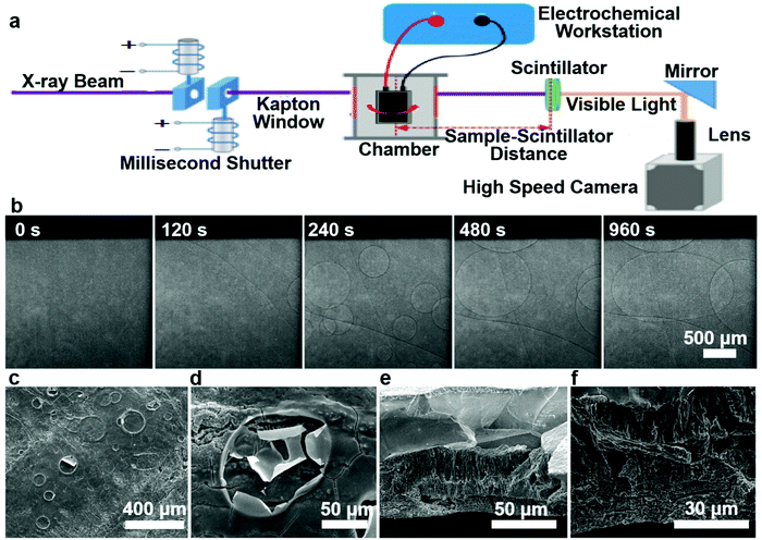
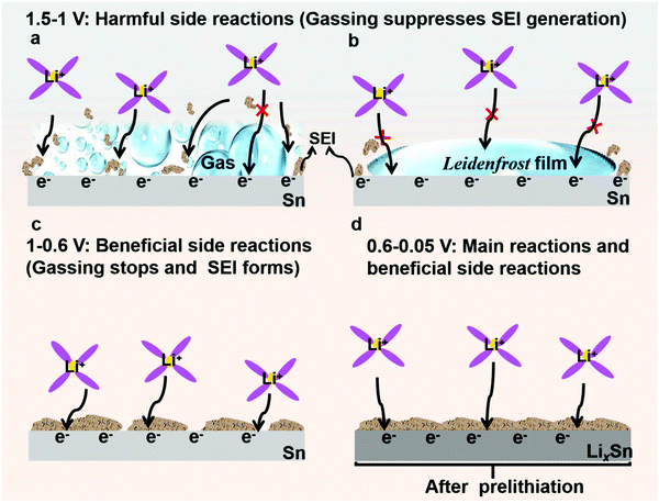
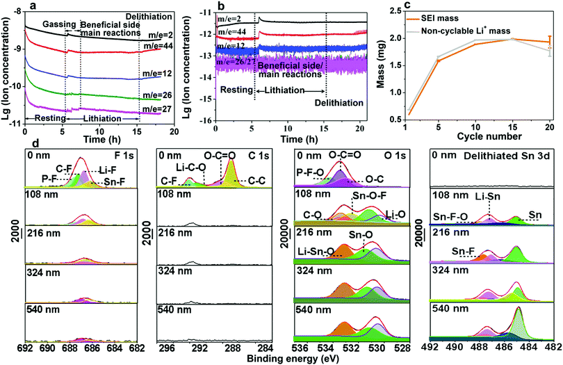
In this work, Sn foil was directly used as both the active anode and current collector in half and full cells. According to the half-cell test result (Fig. S1, ESI†), the initial CE was shockingly low (∼12%), falling far behind that in previous reports of nanoparticle anodes (see Table S1, ESI†). When paired against the commercial ∼2.65 mA h cm−2 LiFePO4 (LFP) cathode in fabricating full cells, a similar result was obtained (Fig. S2, ESI†). Fig. S3, ESI† also shows the fluctuating potential profiles for charge and discharge, which may be related to side reactions. Despite its extremely poor ICE, the Sn//Li half-cell could cycle for more than 250 cycles (see Fig. S1 and S4, ESI†) after activation of the first cycles, which implies the Sn foil electrode may work for LIBs if its ICE problem is solved. To determine the underlying cause, we opened the cell and a large continuous gas bubble was always visually located between the separator and Sn surface (Fig. S5a and b, ESI†). Also, the cycled Sn surface showed bulging and flat regions in the half cell (Fig. S5c, ESI†) and full cells (Fig. S6a and b, ESI†) due to the extremely inhomogeneous reactions. In situ synchrotron imaging (setup illustrated in Fig. 1a) was performed on a LiCoO2//Sn pouch cell, where the evolution of gas bubbles, their growth and fusion into several hundred to one thousand microns were evidently observed (Fig. 1b and Video S1, ESI†). After charging, the pouch cell obviously swelled and there were numerous bubble footprints on the cycled Sn electrode (see Fig. S7a–c and Video S1, ESI†). The as-formed gas layer isolated the Sn electrode from the liquid electrolyte, largely cutting off Li+ transport and causing a rapid increase in the internal resistance of the cells, as illustrated in Fig. 2a. The situation is very similar to the famous Leidenfrost effect22–25 in boiling heat transfer and critical heat flux (CHF), where an insulating vapor layer between the liquid and hot solid surface prevents the liquid from boiling rapidly and causing boilers to explode, as illustrated in Fig. 2b. To confirm the detrimental influence of gassing, we performed electrochemical impedance spectroscopy (EIS) (Fig. S8 and Table S2, ESI†), which revealed a dramatic interfacial resistance increase once cycling was initiated. After reassembling the cells to drive the gasses out of the system, the impedance became smaller, further proving the gas increased the internal resistance.26 Also, it is worth mentioning that the fluctuating surface tension forces of the gas bubbles leaving the electrode eroded the SEI and prevented it from becoming compact and adherent to fully passivate the Sn surface (see Fig. 1c, d and Fig. S9a, b, ESI†). A porous microstructure was viewed on the Sn electrode matrix after the first cycles (Fig. 1e and f), showing that no dense SEI layer covered the Sn foil completely and the electrolyte continued to erode the Sn matrix.The pathway for electrolyte decomposition is voltage-controlled.27 To correlate the relationship between gas evolution and the voltage profile, we fabricated a visual cell of Sn/electrolyte/Li (see Fig. S10a, ESI†). The gas bubbles appeared at around 1.47 V and proliferated rapidly at 1.38 V versus Li/Li+. When the voltage fell below 0.98 V, the production of bubbles became quite slow and then completely stopped at 0.6 V (see Fig. S10b, c, S11, S12 and Video S2, ESI†). Consistent with the above visual observation, a peak at around 1.3–1 V also appeared in the cyclic voltammogram (CV) (Fig. S13, ESI†). Meanwhile, the constitution of gasses collected from the LiCoO2//Sn pouch cell was identified by gas chromatography-mass spectrometry (GCMS), where H2, O2,28,29 CO2 and CnH2n were detected with a volume ratio of 11.31%, 17.74%, 24.95% and 46%, respectively (Fig. S14, ESI†). Furthermore, in situ DEMS measurement was carried out to precisely understand the gassing process and the responses during lithiation–delithiation (Fig. S15, ESI†). As shown in Fig. 3a, CnH2n (pink, green and blue lines), CO2 (red line) and H2 (black line) were detected at the beginning of lithiation in the Sn//Li half-cell and the gas generation finally stopped after 1.5 h. It should be noted that the initial higher amount of gasses during resting is mainly due to the initial unstable baseline calibration, which is generally caused by an insufficient calibration time. After 6 h resting, the baseline was stabilized and there was an obvious increase in the amount of gasses after Sn anode lithiation, which originated from gas generation. The O2 release in the LiCoO2//Sn full cell is probably due to the LiCoO2 cathode.16,17,30 At lower voltages (U ∼ 0.4 V vs. Li/Li+), the gas bubbles and Leidenfrost gas film blocked the Li+ pathway to Sn, where Li+ + e−(U) → LixSn could occur thermodynamically,5 but Li+ could not get to the electron kinetically (as indicated Fig. S16, ESI†). This is also the voltage at which SEI is favored to form, but not in the gas-covered regions, thus delaying the formation of a solid SEI and coverage of the entire surface by the SEI.
Electrolyte decomposition consumes electrons, generating gaseous, solid, and liquid-soluble side products.18,27,31 Among them, the solid products are the most beneficial due to negative feedback (Fig. 2c and d). In contrast, the gaseous products are the most harmful due to positive feedback (Fig. 2a and b) since they can erode the already-formed SEI by fluctuating gas/liquid surface-tension forces, which are known to be mechanically destructive to fragile nanostructured solids. Therefore, understanding SEI growth and adhesion is essential. Based on the mass change with cycling in Fig. 3c, we quantitatively determined the SEI growth of the Sn//Li half cell (see Fig. S17, ESI†) and LiFePO4//Sn full cell (Fig. S18, ESI†). As shown in Fig. 3c, the SEI mass gain (the orange) was less than the hypothetical non-cyclable lithium mass gain according to the coulombic inefficiency cumulant (CIC) analysis32 (the gray) for the first 15 cycles. Thus, Fig. 3c disproves the hypothesis that all the “lost electrons” lead to the formation of solid-only products, which adhere to the electrode. According to the classic SEI model, where lithium combines with O, F or C atoms to form various inorganic and organic salts such as Li2O and Li2CO3, the actual mass of trapped Li should be about 20–30% of the whole SEI weight.33,34 If each “lost electron” from the CIC corresponds to the conversion of a cyclable lithium ion to a trapped non-cyclable lithium ion, the mass gain would have been much greater than what we actually weighed for the washed anode. This means decomposition of electrolyte and salt into solid product is not the only pathway, and gas generation (as well as soluble product generation), prevailed and SEI formation was difficult during the first cycles.
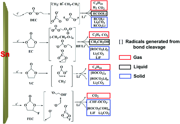
To clarify the degradation chemistry, we further characterized the solid species using XPS. The common carbonaceous species, for example, C–C/C–H, C–O, C![[double bond, length as m-dash]](https://www.rsc.org/images/entities/char_e001.gif) O and C–F and inorganic salts such as LiF, Li2CO3 and Li2O35 were identified by infrared spectrometry (Fig. S19, ESI†). As shown in Fig. 3d and Fig. S20–S22, ESI,† the carbon signal nearly disappeared after Ar ion-etching etched away ∼100 nm. The presence of a P–F signal in the F 1s spectra and P–F–O in the O 1s spectra suggests the decomposition of LiPF6 and formation of PF-containing strong Lewis acids such as PF5 and PF4O, which further react with the Sn surface to generate fluorinated Sn, as revealed in the Sn–F and Sn–F–O signals in both the F 1s spectra and Sn 3d spectra.5 After ∼200 nm sputtering, Sn–F dominates the SEI, indicative of Sn participating in the formation of the SEI. Also, similar result was observed on the freshly lithiated Sn surface (Fig. S23–S25, ESI†), which implies that side reactions occur during the lithiation process. Besides, soluble redox mediators (SRM) from the reductive decomposition of the liquid electrolyte, which may leak “free electrons” through the electrolyte, were also detected by CV (Fig. S26, ESI†), causing an unbalanced consumption of Li+ and electrons (see Fig. S27, ESI†). Based on the above analysis, the possible pathways for carbonate-based electrolyte decomposition catalyzed by tin are illustrated in Fig. 4, where (a) upon catalysis by Sn in a specific potential range, different bond cleavage proceeds to generate various radicals, which is usually accompanied by the release of gas,36–38 (b) once radicals are formed, radical recombination and proton abstraction from the solvent account for the detected compounds, (c) these radicals may be oxidative and then coordinate with the Sn atom on the electrode surface, yielding Li–Sn–O species in the SEI.
O and C–F and inorganic salts such as LiF, Li2CO3 and Li2O35 were identified by infrared spectrometry (Fig. S19, ESI†). As shown in Fig. 3d and Fig. S20–S22, ESI,† the carbon signal nearly disappeared after Ar ion-etching etched away ∼100 nm. The presence of a P–F signal in the F 1s spectra and P–F–O in the O 1s spectra suggests the decomposition of LiPF6 and formation of PF-containing strong Lewis acids such as PF5 and PF4O, which further react with the Sn surface to generate fluorinated Sn, as revealed in the Sn–F and Sn–F–O signals in both the F 1s spectra and Sn 3d spectra.5 After ∼200 nm sputtering, Sn–F dominates the SEI, indicative of Sn participating in the formation of the SEI. Also, similar result was observed on the freshly lithiated Sn surface (Fig. S23–S25, ESI†), which implies that side reactions occur during the lithiation process. Besides, soluble redox mediators (SRM) from the reductive decomposition of the liquid electrolyte, which may leak “free electrons” through the electrolyte, were also detected by CV (Fig. S26, ESI†), causing an unbalanced consumption of Li+ and electrons (see Fig. S27, ESI†). Based on the above analysis, the possible pathways for carbonate-based electrolyte decomposition catalyzed by tin are illustrated in Fig. 4, where (a) upon catalysis by Sn in a specific potential range, different bond cleavage proceeds to generate various radicals, which is usually accompanied by the release of gas,36–38 (b) once radicals are formed, radical recombination and proton abstraction from the solvent account for the detected compounds, (c) these radicals may be oxidative and then coordinate with the Sn atom on the electrode surface, yielding Li–Sn–O species in the SEI.
Roll-to-roll prelithiation suppresses gas generation
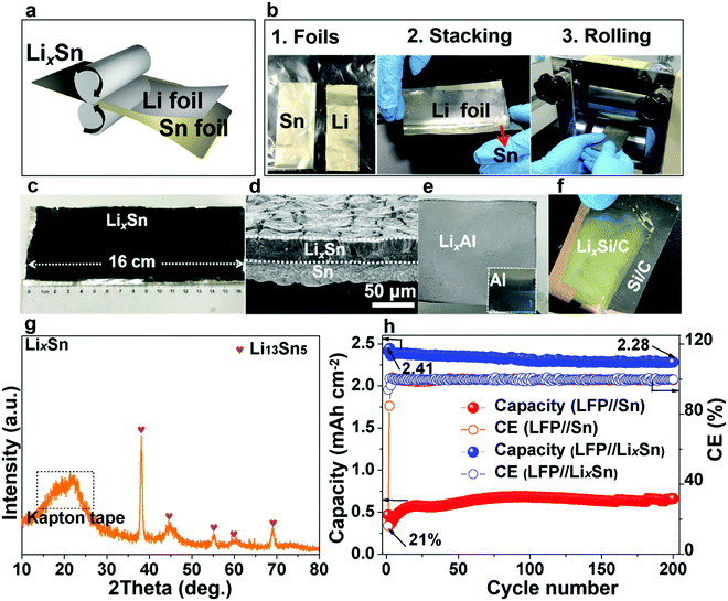
In the previous section, we showed that gassing is voltage-dependent, and when gassing occurs it is difficult for SEI to form and adhere. On the other hand, if a compact SEI has already formed and completely covers the metal surface, then no electrons can tunnel to the liquid electrolyte, shutting down all future side reactions (including gassing), even when the absolute potential cycles back to 1–1.5 V vs. Li/Li+. Inspired by this, we propose that if we start off not with bare Sn, but with lithiated Sn (absolute potential ∼0.4 V vs. Li/Li+), then according to Fig. 2d, we can avoid the dangerous stages of gassing (Fig. 2a and b) and form an adherent SEI directly (Fig. 2c) from the beginning. Once the SEI is formed, all side reactions including gassing will be suppressed in later cycles (Fig. 2d).Many researchers perform pre-lithiation electrochemically, but electrochemical pre-lithiation gives a spatially inhomogeneous outcome due to the gassing problem. Here, we developed a scalable roll-to-roll approach of metallurgically pre-alloying Sn with Li to form LixSn foil (illustrated in Fig. 5a), without using any electrolyte, by thermomechanical pressing only. The specific operations are shown in Fig. 5b, where stacked Sn and Li foils were pressed by a roller. After the metallurgical bonding, reaction and debonding process, the Li-facing sides of Sn foils turned dark, indicative of LixSn alloy formation, while the substrate beneath maintained the metallic luster of fresh tin, which works well as a current collector, as shown in Fig. 5c. As shown in Fig. 5d, two adjacent layers of LixSn (∼30 μm) and Sn substrate (∼25 μm) could be identified and the thickness of the LixSn layer was fairly homogeneous. Also, we randomly punched three coin-cell disks from the prelithiated foil in Fig. 5c, and the areal capacity remained at ∼3.2 mA h cm−2 (see Fig. S28, ESI†), indicating the lithiation was extremely uniform. It should be noted that the rolling pressure is a fairly key factor that affects the formation of Li–Sn alloy. For example, when the pressure was 10 MPa, the prelithiation degree is quite low and a large amount of unreacted lithium could be observed on Sn surface (see Fig. S29a, ESI†). After peeling off the residual lithium, the as-obtained LixSn foil (Fig. S29b, ESI†) was delithiated to 1.5 V in a half cell and the delithiation capacity was 1.1 mA h cm−2 (Fig. S30, the black, ESI†). This situation was improved when the pressure increased to 20 MPa, although there was still a thin layer of remaining lithium (see Fig. S29c, ESI†). After peeling off this residual lithium metal (Fig. S29d, ESI†), the lithium capacity in the Li–Sn alloy was estimated to be 2.3 mA h cm−2 (Fig. S30, red, ESI†). Once the pressure reached 30 MPa, the Li foil was totally consumed by the Sn matrix to form the Li–Sn alloy (see Fig. S29e and f, ESI†), and the lithium capacity was 3.2 mA h cm−2 (Fig. S30, blue, ESI†). In the XRD pattern, only peaks for Li13Sn5 were detected (Fig. 5g),14,39 implying that the as-formed LixSn alloy is a single phase. In addition, we also prepared LixAl, LixSi/C using the same method, as demonstrated in Fig. 5e and f. The as-formed LixAl and LixSi/C electrodes could extract a lithium capacity of 4.45 and 2.2 mA h cm−2 electrochemically (Fig. S31 and S32, ESI†), respectively, showing our mechanical prelithiation approach is universally applicable.
DEMS examination of the LixSn//Li cell (Fig. 3b) revealed the gas amount decreased by a factor of ∼103 compared with the pristine Sn counterpart (Fig. 3a), and in parallel the SEI weight gain increased (Fig. S33 and S34, ESI†), indicating adherent SEI formation prevailed and gas generation was suppressed. Additionally, the XPS depth profiling analysis demonstrated that the SEI layer became much denser on the LixSn surface (Fig. S35, ESI†). The lithium inventory that could be extracted from the pre-lithiated Sn foil was estimated by delithiating to 1.5 V in a half cell, and a high delithiation capacity of 3.18 mA h cm−2 was found (Fig. S36, ESI†). We then paired the as-obtained pre-lithiated Sn anode against LFP cathodes of 2.65 mA h cm−2 areal capacity, i.e. making a full cell with 1.2× excess Li.21 In contrast to the LFP//Sn charge curve (blue line), where the voltage fluctuated wildly from 3.5 V due to floating gas bubbles in the cell (see Fig. S37, ESI†), the LFP//LixSn full cell was stable. The SEM images (Fig. S38 and S39, ESI†) after cycling demonstrated a much denser SEI layer, suggesting our prelithiation strategy retarded the gassing and helped the SEI film to rapidly form. The ICE of the LFP//LixSn full cells was as high as 94% (comparable to commercial graphite), and the CE reached 99.5% in the 2nd cycle, which is also competitive with graphite (rising to 99.5% in 4–5 cycles). Even after 200 cycles, a capacity of 2.28 mA h cm−2 was maintained, which gave 94.5% capacity retention (Fig. 5h and Fig. S40, ESI†). It is worth noting that the voltage drift in the discharge and charge curves in Fig. S40, ESI† is because the lithium inventory of the initially lithium-rich anode was depleted after long cycling, causing the absolute anode potential to up-shift and the full-cell voltage to decrease.
Air stability and volumetric capacity
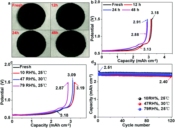
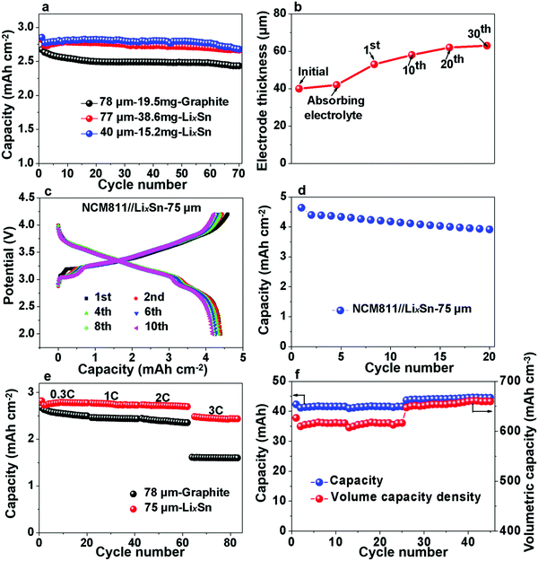
Pre-lithiation of anodes is a common strategy to counter the problem of coulombic inefficiency and loss of cyclable lithium during cycling. However, because lithium metal foil and/or prelithiated graphite must be handled in a moisture-controlled environment, this often greatly increases the manufacturing cost. The air stability of electrode materials is extremely important for the battery industry, especially during handling and battery assembly. Thus, the use of prelithiated anodes in an open environment instead of glove boxes and dry rooms is highly desirable. Therefore, we further examined the air stability of our prelithiated Sn anode exposed to ambient air with a gradually increasing relative humidity (RH). Visually, there was no observable change except that the surface color became slightly gray after 48 h, as revealed in Fig. 6a. With regard to the electrochemical performance, after exposure to ambient air for 48 h, the foil still exhibited an areal capacity of 2.88 mA h cm−2, which is 90.8% of its original capacity in Fig. 6b. As can be seen in Fig. 6c, the humidity tolerance of the pre-lithiated Sn anodes was surprisingly excellent, and the samples demonstrated industrially acceptable capacity retention even after 12 h exposure, with no observable capacity decay after exposure to ambient air of various humidity. It is also interesting to note that the exposure to ambient air had a negligible effect on the cycle life, as revealed in Fig. 6d. When pairing the pre-lithiated Sn anodes that were exposed to air with as high as 79% RH for 12 h against the commercial 2.65 mA h cm−2 LFP cathode, the initial coulombic efficiency was 95%, which rapidly increased to 100% in the third cycle, and then maintained an average CE of 99.948% in the following 120 cycles.Additionally, we also evaluated the practical implications of the LixSn anode by comparing its volumetric capacity with that of commercial graphite. When paired against the 2.65 mA h cm−2 LFP cathode, the areal capacity of 78 μm-thick graphite electrodes was ∼2.12 mA h cm−2, while 77 μm and 40 μm pre-lithiated Sn anodes showed a capacity of 2.4 mA h cm−2 and 2.48 mA h cm−2, respectively (Fig. 7a). Note that the 40 μm LixSn alloy with a similar areal capacity has just ∼50% thickness of the graphite anode initially, although the thickness expanded to ∼60 μm after 30 cycles, and remained stable thereafter (Fig. 7b). We also paired LixSn against the NCM811 cathode for higher voltage and larger areal capacity. When the NCM811//LixSn full cell was charged to 4.3 V, the LixSn anode still performed well (Fig. 7c), and the areal capacity density remained at ∼4.25 mA h cm−2 after the 20th cycle (Fig. 7d). Here, it should be noted that the slight capacity attenuation is due to the decay of the NCM811 cathode. To evaluate the rate performance of LixSn, we chose the more stable LFP cathode, from which the rate performance is shown in Fig. 7e, where the capacity was maintained at 2.3–2.4 mA h cm−2 even when the charging and discharging rate reached as high as 2C, while the graphite anode provided 2.1–2.2 mA h cm−2. At 3C, the capacity of the LixSn alloy remained at ∼1.99 mA h cm−2, while that of the graphite anode dropped drastically to ∼1.42 mA h cm−2 due to lithium-metal precipitation on the surface of graphite. Lithium-metal (BCC) precipitation is much less likely in the LixSn anode due to its higher absolute potential and better electrical conduction.
Finally, we assembled large-format pouch cells for estimating the capacity density of the LixSn foil, and the thickness of the entire pouch cell was measured in real time. Assuming that the cell swelling primarily originates from the thickness increase of the anodes, we calculated the volumetric capacity of the Sn anodes, as shown in Fig. 7f. Initially, the capacity was stable at ∼41 mA h for the 3 cm × 2.5 cm pouch and the volumetric capacity of LixSn was ∼615 mA h cm−3. Afterwards, the capacity increased to ∼44 mA h, and the volume capacity density was maintained at ∼650 mA h cm−3, while that for the graphite with copper backing was only 500 mA h cm−3. Thus, the LixSn alloy exhibited easy handling in open-air environment, higher volumetric capacity and better fast-charging capability than the conventional graphite anode. With further optimization in manufacturing, thinner LixSn foils can be fabricated, and therefore even higher volumetric capacities may be achievable in the future.
Conclusion
Tin, as a promising alternative anode for LIBs, suffers from a low ICE and poor cycle life. In this study, we demonstrated that bare Sn catalyzed electrolyte decomposition at an intermediate voltage to generate gas bubbles and Leidenfrost gas films, which cut off the paths of lithium ions and prevented adherent SEI formation. A lower absolute potential (below 1 V) is more advantageous for adherent SEI formation, which can suppress future gassing. Therefore, mechanical prelithiation, which creates highly uniform LixSn alloy, can effectively suppress gassing and greatly improve the ICE. We developed a roll-to-roll mechanical prelithiation process, which improved the capacity retention to 94.5% after 200 cycles at 0.3C. Also, the air stability of the prelithiated Sn foils was excellent, where 12 h exposure to humidity did not degrade their capacity or cycle life significantly. The cycling volumetric capacity of the LixSn alloy is ∼650 mA h cm−3, which is significantly better than that of graphite anode on copper, with a rate capability as high as 3C. Our study provides vital new insights into the degradation mechanisms of Sn anodes in LIBs and developed an effective mitigation strategy, which may be applicable to other metallic alloy anode materials.Experimental
Materials
Sn foil (100 μm, 99.99%, Jinan Dingsheng Metal Materials Co., Ltd) was punched into disks with a diameter of 12 mm and directly used as working electrodes. Lithium metal was paired against a Sn foil electrode in a half cell and the commercial LiFePO4 cathode (∼2.65 mA h cm−2) with a diameter of 12 mm was used in the full cell. The commercial graphite anode (∼2.65 mA h cm−2) with a diameter of 12 mm was used in the LFP//graphite full cells. 40 μL electrolyte of EC/DEC (v/v = 1![[thin space (1/6-em)]](https://www.rsc.org/images/entities/char_2009.gif) :
:![[thin space (1/6-em)]](https://www.rsc.org/images/entities/char_2009.gif) 1) with 10% FEC and 1% VC as additives was used. A self-made beaker battery was built to dynamically visualize the lithiation–delithiation process inside the batteries and in situ capture the electrochemical reaction phenomenon. Besides, the LiCoO2//Sn pouch was assembled to collect the gas byproducts. For the roll-to-roll prelithiation, 50 μm Li foil (China Energy Lithium Co., Ltd) and Sn foil (40–100 μm) were rolled with a roller (MSK-2150, Shenzhen Kejing Star Technology, Ltd) in air at 30 MPa pressure.
1) with 10% FEC and 1% VC as additives was used. A self-made beaker battery was built to dynamically visualize the lithiation–delithiation process inside the batteries and in situ capture the electrochemical reaction phenomenon. Besides, the LiCoO2//Sn pouch was assembled to collect the gas byproducts. For the roll-to-roll prelithiation, 50 μm Li foil (China Energy Lithium Co., Ltd) and Sn foil (40–100 μm) were rolled with a roller (MSK-2150, Shenzhen Kejing Star Technology, Ltd) in air at 30 MPa pressure.
Electrochemical measurements
The electrochemical performance was measured in CR2025 coin-type batteries using a test system (CT-4008, Neware). The Sn//Li half-cell was lithiated to 3 mA h and delithiated to 1.5 V at a rate of 0.3C. The LiCoO2//Sn pouch cell was charged to 4.2 V at a current density of 1 mA cm−2 to collect the gas. The beaker battery was lithiated to 3 mA h and delithiated to 1.5 V at a current density of ∼0.1 mA cm−2 to in situ monitor the gas behavior. Cyclic voltammetry scanning was carried out on an electrochemical workstation (CHI660E, Shanghai Chen Hua Instrument Co., Ltd) in the potential range of 0 to 2 V at a scan rate of 0.5 mV s−1.Characterization
The gas collected from the LiCoO2//Sn pouch cell was analyzed using a gas chromatography-mass spectrometry (GC-MS, Finniga DSQ). Differential electrochemical mass spectrometer (DEMS, QAS 100) was provided by Linglu Instruments (Shanghai) Co. Ltd to perform in operando analysis of the gas. In situ examination of the battery internal changes and gas evolution were conducted using X-ray synchrotron radiation at Shanghai Synchrotron Radiation Facility. The surface and cross-section structure of the cycled Sn foil were observed via field emission scanning electron microscopy (SEM, FEI Quanta 200). The composition of the SEI was analyzed using an infrared spectrometer (IR, Bruker Optics EQUINOX55) and X-ray photoelectron spectroscopy (XPS, American Thermo Fisher Scientific ESCALAB 250Xi). The etching speed for the XPS depth analysis was 0.27 nm s−1 and 200 s each time. The crystalline phase of the LixSn alloy was identified by X-ray diffraction (XRD, Bruker AXS GMBH GERM D8) with CuKα radiation (λ = 1.54184 Å). The signal was detected for diffraction angles (2θ) between 10° and 80° at a scan rate of 3° min−1, and Kapton tape was used to protect the LixSn alloy from air contamination.Conflicts of interest
There are no conflicts to declare.Acknowledgements
The authors are grateful for assistance by Dr Zhilong Li in in situ synchrotron radiation characterization, guidance by Dr Zhengzheng Li from Shanghai Baosteel Corporation in assembling the pouch cells, assistance by Linglu instruments (Shanghai) Co. Ltd in DEMS test, and the support from Tongji University and the National Natural Science Foundation of China (NSFC-No. 51602222 and 51632001). SL acknowledges the support by the Fundamental Research Funds for the Central Universities (No. 0500219233); JL acknowledges the support by Samsung Advanced Institute of Technology; WL, XC and CZ acknowledge the support by National College Students Innovation and Entrepreneurship Training Program (No. 0500107107).Notes and references
- W. Choi, J. Y. Lee, B. H. Jung and H. S. Lim, J. Power Sources, 2004, 136, 154–159 CrossRef CAS.
- K. Eom, J. Jung, J. T. Lee, V. Lair, T. Joshi, S. W. Lee, Z. Lin and T. F. Fuller, Nano Energy, 2015, 12, 314–321 CrossRef CAS.
- G. M. Veith, M. Doucet, J. K. Baldwin, R. L. Sacci, T. M. Fears, Y. Wang and J. F. Browning, J. Phys. Chem. C, 2015, 119, 20339–20349 CrossRef CAS.
- T. Ma, X. Yu, H. Li, W. Zhang, X. Cheng, W. Zhu and X. Qiu, Nano Lett., 2017, 17, 3959–3964 CrossRef CAS PubMed.
- N. Tamura, R. Ohshita, M. Fujimoto, S. Fujitani, M. Kamino and I. Yonezu, J. Power Sources, 2002, 107, 48–55 CrossRef CAS.
- L. Ji, Z. Lin, M. Alcoutlabi and X. Zhang, Energy Environ. Sci., 2011, 4, 2682–2699 RSC.
- M. Inaba, T. Uno and A. Tasaka, J. Power Sources, 2005, 146, 473–477 CrossRef CAS.
- M. Jeong, T. Yokoshima, H. Nara, T. Momma and T. Osaka, J. Power Sources, 2015, 275, 525–530 CrossRef CAS.
- S. Zhang, K. Zhao, T. Zhu and J. Li, Prog. Mater. Sci., 2017, 89, 479–521 CrossRef CAS.
- K. Saravanan, M. Nagarathinam, P. Balaya and J. J. Vittal, J. Mater. Chem., 2010, 20, 8329–8335 RSC.
- H. Sun, G. Xin, T. Hu, M. Yu, D. Shao, X. Sun and J. Lian, Nat. Commun., 2014, 5, 4526 CrossRef CAS PubMed.
- L. Yang, T. Dai, Y. Wang, D. Xie, R. L. Narayan, J. Li and X. Ning, Nano Energy, 2016, 30, 885–891 CrossRef CAS.
- J. Patra, P. C. Rath, C. Li, H.-M. Kao, F.-M. Wang, J. Li and J.-K. Chang, ChemSusChem, 2018, 11, 3923–3931 CrossRef CAS PubMed.
- G. Derrien, J. Hassoun, S. Panero and B. Scrosati, Adv. Mater., 2007, 19, 2336–2340 CrossRef CAS.
- S. Etezadi, A. Koppaka, M. M. Gamage and B. Captain, J. Organomet. Chem., 2017, 848, 122–132 CrossRef CAS.
- Q. Hou, M. Zhen, L. Liu, Y. Chen, F. Huang, S. Zhang, W. Li and M. Ju, Appl. Catal., B, 2018, 224, 183–193 CrossRef CAS.
- P. Manjunathan, V. S. Marakatti, P. Chandra, A. B. Kulal, S. B. Umbarkar, R. Ravishankar and G. V. Shanbhag, Catal. Today, 2018, 309, 61–76 CrossRef CAS.
- J.-S. Bridel, S. Grugeon, S. Laruelle, J. Hassoun, P. Reale, B. Scrosati and J.-M. Tarascon, J. Power Sources, 2010, 195, 2036–2043 CrossRef CAS.
- T. Liu, L. Lin, X. Bi, L. Tian, K. Yang, J. Liu, M. Li, Z. Chen, J. Lu, K. Amine, K. Xu and F. Pan, Nat. Nanotechnol., 2019, 14, 50–56 CrossRef CAS PubMed.
- L. Suo, D. Oh, Y. Lin, Z. Zhuo, O. Borodin, T. Gao, F. Wang, A. Kushima, Z. Wang, H.-C. Kim, Y. Qi, W. Yang, F. Pan, J. Li, K. Xu and C. Wang, J. Am. Chem. Soc., 2017, 139, 18670–18680 CrossRef CAS PubMed.
- L. Suo, W. Xue, M. Gobet, S. G. Greenbaum, C. Wang, Y. Chen, W. Yang, Y. Li and J. Li, Proc. Natl. Acad. Sci. U. S. A., 2018, 115, 1156–1161 CrossRef CAS PubMed.
- R. S. Hall, S. J. Board, A. J. Clare, R. B. Duffey, T. S. Playle and D. H. Poole, Nature, 1969, 224, 266 CrossRef CAS.
- B. S. Gottfried, C. J. Lee and K. J. Bell, Int. J. Heat Mass Transfer, 1966, 9, 1167–1188 CrossRef CAS.
- V. V. Yagov, M. A. Lexin, A. R. Zabirov and O. N. Kaban’kov, Int. J. Heat Mass Transfer, 2016, 100, 908–917 CrossRef CAS.
- Z. Wang, J. Xiong, W. Yao, W. Qu and Y. Yang, Int. J. Heat Mass Transfer, 2019, 128, 1206–1217 CrossRef CAS.
- S. Li, M. Jiang, Y. Xie, H. Xu, J. Jia and J. Li, Adv. Mater., 2018, 30, 1706375 CrossRef PubMed.
- L. Y. Beaulieu, S. D. Beattie, T. D. Hatchard and J. R. Dahn, J. Electrochem. Soc., 2003, 150, A419–A424 CrossRef CAS.
- S. Levasseur, M. Ménétrier, Y. Shao-Horn, L. Gautier, A. Audemer, G. Demazeau, A. Largeteau and C. Delmas, Chem. Mater., 2003, 15, 348–354 CrossRef CAS.
- Y. Baba, S. Okada and J.-I. Yamaki, Solid State Ionics, 2002, 148, 311–316 CrossRef CAS.
- M. Mohan Rao, M. Jayalakshmi, O. Schäf, H. Wulff, U. Guth and F. Scholz, J. Solid State Electrochem., 2001, 5, 50–56 CrossRef.
- S. D. Beattie, T. Hatchard, A. Bonakdarpour, K. C. Hewitt and J. R. Dahn, J. Electrochem. Soc., 2003, 150, A701–A705 CrossRef CAS.
- Y. Jin, S. Li, A. Kushima, X. Zheng, Y. Sun, J. Xie, J. Sun, W. Xue, G. Zhou, J. Wu, F. Shi, R. Zhang, Z. Zhu, K. So, Y. Cui and J. Li, Energy Environ. Sci., 2017, 10, 580–592 RSC.
- L. M. Z. De Juan, I. V. B. Maggay, M. T. Nguyen, W.-R. Liu and T. Yonezawa, ACS Appl. Nano Mater., 2018, 1, 3509–3519 CrossRef CAS.
- M. Herstedt, H. Rensmo, H. Siegbahn and K. Edström, Electrochim. Acta, 2004, 49, 2351–2359 CrossRef CAS.
- H. J. Santner, C. Korepp, M. Winter, J. O. Besenhard and K.-C. Möller, Anal. Bioanal. Chem., 2004, 379, 266–271 CrossRef CAS PubMed.
- A. Schiele, B. Breitung, T. Hatsukade, B. B. Berkes, P. Hartmann, J. Janek and T. Brezesinski, ACS Energy Lett., 2017, 2, 2228–2233 CrossRef CAS.
- C. Han, Y.-B. He, M. Liu, B. Li, Q.-H. Yang, C.-P. Wong and F. Kang, J. Mater. Chem. A, 2017, 5, 6368–6381 RSC.
- M. Metzger, B. Strehle, S. Solchenbach and H. A. Gasteiger, J. Electrochem. Soc., 2016, 163, A798–A809 CrossRef CAS.
- K. K. D. Ehinon, S. Naille, R. Dedryvère, P. E. Lippens, J. C. Jumas and D. Gonbeau, Chem. Mater., 2008, 20, 5388–5398 CrossRef CAS.
Footnotes |
| † Electronic supplementary information (ESI) available. See DOI: 10.1039/c9ee01404g |
| ‡ These authors contributed equally to this work. |
| This journal is © The Royal Society of Chemistry 2019 |

