 Open Access Article
Direct observation of active catalyst surface phases and the effect of dynamic self-optimization in NiFe-layered double hydroxides for alkaline water splitting†
Zhen
Qiu
 a,
Cheuk-Wai
Tai
 b,
Gunnar A.
Niklasson
 a and
Tomas
Edvinsson
 *a
*a
aDepartment of Engineering Sciences, Solid State Physics, Uppsala University, Box 534, SE-75121, Uppsala, Sweden. E-mail: tomas.edvinsson@angstrom.uu.se
bDepartment of Materials and Environmental Chemistry, Stockholm University, SE-10691, Stockholm, Sweden
First published on 4th January 2019
Abstract
Earth-abundant transition metal-based compounds are of high interest as catalysts for sustainable hydrogen fuel generation. The realization of effective electrolysis of water, however, is still limited by the requirement of a high sustainable driving potential above thermodynamic requirements. Here, we report dynamically self-optimized (DSO) NiFe layered double hydroxide (LDH) nanosheets with promising bi-functional performance. Compared with pristine NiFe LDH, DSO NiFe LDH exhibits much lower overpotential for the hydrogen evolution reaction (HER), even outperforming platinum. Under 1 M KOH aqueous electrolyte, the bi-functional DSO catalysts show an overpotential of 184 and −59 mV without iR compensation for oxygen evolution reaction (OER) and HER at 10 mA cm−2. The material system operates at 1.48 V and 1.29 V to reach 10 and 1 mA cm−2 in two-electrode measurements, corresponding to 83% and 95% electricity-to-fuel conversion efficiency with respect to the lower heating value of hydrogen. The material is seen to dynamically reform the active phase of the surface layer during HER and OER, where the pristine and activated catalysts are analyzed with ex situ XPS, SAED and EELS as well as with in situ Raman spectro-electrochemistry. The results show transformation into different active interfacial species during OER and HER, revealing a synergistic interplay between iron and nickel in facilitating water electrolysis.
Broader contextEarth-abundant transition metal-based catalysts are of high interest in sustainable fuel generation as they potentially provide a dramatic lowering of costs and enable scalability beyond the Gigawatt scale. The realization of effective electrolysis of water in alkaline conditions, however, is still limited by the requirement of a high sustainable driving potential above thermodynamic requirements. Here we report dynamically self-optimized NiFe layered double hydroxides (LDHs) that show excellent performance for both the hydrogen (HER) and oxygen evolution reaction (OER) with 83–95% electricity-to-fuel conversion efficiency in the range 10–1 mA cm−2 and −59 mV and 184 mV overpotential for the HER and the OER at 10 mA cm−2. The active surface phases during the HER and OER reactions are characterized with a variety of ex situ and in situ techniques and add fundamental insights in the prevailing oxidation states and phases dynamically formed during the reactions, revealing a synergistic interplay between iron and nickel in facilitating effective water electrolysis via oxyhydroxides. The study shows that transition metal oxyhydroxides operate as effective bi-functional catalysts in alkaline water splitting, promising for integration into renewable technologies such as fuel formation from wind- or solar based electricity in electrolyzers for sustainable production of hydrogen or other clean fuels. |
Introduction
Highly efficient, low-cost and long-lived catalysts are crucial components in energy conversion of electricity into fuels and chemicals.1 Renewable energy from wind and solar is strongly intermittent in nature where diurnal or seasonal variations motivate storage of the energy for later use.2,3 For short term storage, batteries are promising alternatives with close to unity in columbic efficiency but less efficient for storage over weeks and seasons due to natural self-discharge.4 Pb–, Ni–metal-hydride, and Li-based batteries would need periodic recharge to compensate for energy losses if not used within a few days. In addition, although almost all the stored electrons can be extracted, the system normally has to be charged at a higher potential than the operating voltage, resulting in a power efficiency of between 70 and 98% depending on battery type and charge rate,5 where fast charging results in lower power efficiencies. Storage of wind and solar energy in zero-emission fuels such as hydrogen is here an alternative that can be used for heating or electricity on-demand to achieve versatile utilization of the energy at a later stage.6,7 This approach8,9 has so far been hampered by much lower power efficiency in the conversion from electricity to fuel, the difficulty in scalability due to the use of precious elements and limitations in the fuel-cell power conversion efficiency (PCE). In this study, we show that DSO Ni–Fe based catalysts provide a promising solution to the first two obstacles.Water electrolysis offers an effective way to produce high-purity hydrogen10,11 where renewable electricity from wind and solar energy can be utilized. Renewable electricity-driven water splitting technologies largely rely on anode and cathode reactions, with a need for catalysts to lower the overpotential required above the thermodynamic requirements of 1.229 V.12 Most commercially available water electrolyzers are mainly operated under either strong alkaline or strongly acidic conditions.13,14 However, the conditions and processes required to produce optimal catalysts are typically different for OER and HER, which could result in manufacturing complexity and cost increase.15 Here it is meaningful but challenging to develop promising bi-functional catalysts for an overall system. Considering the earth-abundance and cost-efficiency, great attention has been given to first-row transition metal-based compounds, including transition metal alloys, oxides/hydroxides/oxyhydroxides, nitrides, phosphides, sulfides, and selenides. Among these, most of the studies are performed only for a half-reaction, either OER16–19 or HER,20–22 while a few are suitable and investigated for both reactions as a water electrolyzer.23–25 In addition, the starting material is seldom the same as the active material created under the strongly acidic or alkaline conditions under different applied bias as evident from normal Pourbaix diagram analysis, and this is further complicated by the inclusion of several metals. Herein, we report a dynamically self-optimized NiFe LDH catalyst, which does not only show low OER overpotential but also accelerate electron transfer and gas release for the HER reaction. The prevailing oxidations states and the crystallinity of the pristine and self-optimized catalysts were analyzed with XPS, TEM and EELS analysis. In situ Raman electro-spectroscopy was utilized to monitor the active surface phases during OER and HER, and the role of Ni and Fe at different potentials.
Results and discussion
Electrochemical analysis
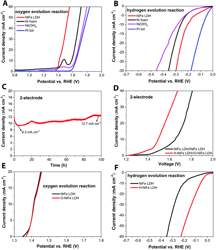
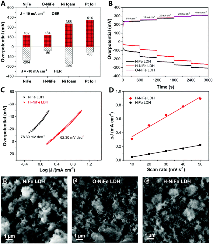
The anodic performance of the catalyst was characterized by linear sweep voltammetry (LSV) in a three-electrode configuration at a scan rate of 5 mV s−1 under 500 rpm magnetic stirring (Fig. 1A, cf. other stirring rates in Fig. S1, ESI†). For comparison, pristine Ni foam and platinum (Pt) foil were studied under identical conditions. In Fig. 2A, it is seen that the fresh NiFe LDH only required 182 mV overpotential (ηOER) to reach 10 mA cm−2 in 1 M KOH, which is considerably less than the bare Ni foam (355 mV), Ni(OH)2 (402 mV) and Pt foil (414 mV). As a cathode, the fresh NiFe LDH exhibits an overpotential (ηHER) of −204 mV to reach a current density of 10 mA cm−2. The HER property of the fresh NiFe LDH is better than the pristine Ni foam and Ni(OH)2 but not as good as the Pt foil (Fig. 1B). Inspired by the function of aging and the importance of durability of the electrolyzer system, we tested the performance of the electricity-driven water electrolyzer at 1.7 V for 100 h in base electrolyte at room temperature. As seen in Fig. 1C, the corresponding current density (normalized to the geometric area) presents a notable increase from 9.3 mA cm−2 to 12.7 mA cm−2. The catalytic properties of the overall water splitting before and after 100 h electrolysis were investigated by LSV (Fig. 1D). The aged catalyst shows that only 1.48 V and 1.29 V are required to achieve 10 mA cm−2 and 1 mA cm−2 water splitting current density in a two-electrode configuration. Their corresponding electricity-to-hydrogen efficiencies are 83–95%, with respect to the lower heating value of hydrogen (237.18 kJ per mol produced H2 or 1.229 V), while current commercial electrolyzers operate at an efficiency between 60 to 73%.26 The operating current densities are typically higher in commercial electrolyzers whereas 10 mA cm−2 and 1 mA cm−2 are commonly the current density range used in upcoming, not yet commercialized, technologies such as photocatalysis, PV-electrolysis and fast charging Li-ion battery technologies. A note of comparison; the upper current density of 10 mA cm−2 corresponds to quite harsh charging conditions with about 1.5 times higher charging current densities than the ones used in conventional graphite based Li-ion batteries as well as among the highest reported for the full water splitting reactions in photocatalysis, while the lower current density corresponds to slow charging.27 In order to identify the dominant contribution to the increased performance in the NiFe LDH catalyst, the anodic and cathodic half-cell reaction was measured by the corresponding aged catalysts (O-NiFe LDH and H-NiFe LDH) in a three-electrode configuration, separately. The anodic catalytic property was not appreciably changed at the current density of 10 mA cm−2 (Fig. 1E). Interestingly, the cathodic performance on H-NiFe LDH exhibits a more than 2-fold decrease of the overpotential after prolonged use, ultimately requiring −59 mV overpotential to achieve the current density of 10 mA cm−2 (Fig. 1F). In addition, for comparison, the aging process on Ni foam and Ni(OH)2 were studied as well (Fig. S2, ESI†). As shown in Fig. S2 and Table S1 (ESI†), Ni foam exhibits a large current decrease with time, effectively showing that the improved performance of aged NiFe LDH is not due to the Ni foam substrate. The increased activity of aged Ni(OH)2 matched well with previous reports28,29 that the incorporation of Fe in unpurified 1 M KOH promotes the catalytic activity and further indicates the importance to study the property of NiFe LDH.Overall, the whole overpotential of aged-NiFe LDH was 243 mV, which is 251 mV lower than that of the commercial Pt foil (with a total overpotential of 494 mV) tested under identical conditions (Fig. 2A). A multi-step chronopotentiometric comparison in a three-electrode configuration (Fig. 2B) shows a negligible change with current density for the anodic catalytic property, while the H-NiFe LDH exhibited improved HER catalytic performance for all the increased current densities from −5 mA cm−2 to −40 mA cm−2. These chronopotentiometric responses are consistent with the LSV results, which reflects that H-NiFe LDH possesses excellent mass transport properties and a lower activation barrier. To gain an insight into the overall reaction kinetics and dominating reaction steps, Tafel plots were constructed as shown in Fig. 2C and Fig. S2 (ESI†). The Tafel slope of 62.3 mV dec−1 for H-NiFe LDH is lower than that of NiFe LDH (78.39 mV dec−1), confirming the intrinsic favorable catalytic property of H-NiFe LDH. In alkaline media, the hydrogen evolution reaction on the surface of metal (M), or metal composites, contains two primary steps, involving an electron transfer process that forms the adsorbed hydrogen, (H2O + M + e− ↔ M–Hads + OH−, Volmer reaction) together with an electrochemical desorption process (H2O + M–Hads + e− ↔ M + H2 + OH−, Heyrovsky reaction) or a chemical desorption process (2M–Hads ↔ 2M + H2, Tafel reaction). According to the HER kinetic model,30 the Tafel slope of 62.3 mV dec−1 on the surface of H-NiFe LDH is between the theoretical values for the rate-determining Volmer (120 mV dec−1) and Heyrovsky (40 mV dec−1) cases and thus indicates that the HER is proceeding via a Volmer–Heyrovsky reaction, which is assumed to be the same in the HER process on NiFe LDH. In the OER process (Fig. S3C, ESI†), the Tafel slope of O-NiFe LDH (28.83 mV dec−1) is similar to that of NiFe LDH (34.34 mV dec−1), close to 2.303(RT/2F) V per decade at a temperature of T = 298.15 K, suggesting that combination of MOH is rate determining.31,32 According to the Tafel equation η = b × log![[thin space (1/6-em)]](https://www.rsc.org/images/entities/char_2009.gif) J + a, the exchange current density (J0) of NiFe LDH and H-NiFe LDH is 0.38 mA cm−2 and 1.85 mA cm−2 respectively. A large J0 indicates a large surface area, fast electron transfer rate, and favorable HER kinetics,33 which means that the H-NiFe LDH has been markedly improved for HER.
J + a, the exchange current density (J0) of NiFe LDH and H-NiFe LDH is 0.38 mA cm−2 and 1.85 mA cm−2 respectively. A large J0 indicates a large surface area, fast electron transfer rate, and favorable HER kinetics,33 which means that the H-NiFe LDH has been markedly improved for HER.
Complementary evidence for the HER mechanism was obtained by electrochemical impedance spectroscopy (EIS, Fig. S4, ESI†). The Nyquist plot shows a semicircular arc with a much smaller diameter for H-NiFe LDH than that of NiFe LDH. The low frequency intersections of the semicircle with the real impedance axis signify a smaller reaction resistance for H-NiFe LDH, which implies a lower reaction barrier for hydrogen generation. In addition, the inductive behavior at large overpotentials in the low frequency range is weakened for H-NiFe LDH. The presence of a low frequency inductance is also a signature of the dominating Volmer–Heyrovsky reaction since the Volmer–Tafel reaction cannot give rise to inductive behavior.34 Note that the inductive response is not directly related to the surface coverage,35 but instead to the surface coverage relaxation, i.e. the part of the current originating from a change in surface coverage.
The reaction resistance for OER at 400 mV was not evolved to a full semi-circle (Fig. S5, ESI†) but confirms a similar reaction resistance for both the pristine and aged catalyst (NiFe LDH and O-NiFe LDH) as it is below 1 Ω for both cases. The electrochemical double-layer capacitance (Cdl) was estimated by cyclic voltammetry (CV) in the non-faradic reaction range (Fig. S6, ESI†). It is proportional to the electrochemical active surface area (ECSA). The current difference (ΔJ = Ja − Jc) at multiple scan rates was used to estimate Cdl, where the slope is two times Cdl. From Fig. 2D, it is clear that Cdl of H-NiFe LDH is 7.22 mF cm−2, about three times larger than that of NiFe LDH (2.16 mF cm−2). The larger surface coverage of active sites in H-NiFe LDH promotes the electrocatalytic reaction rate and hydrogen production.
Material analysis
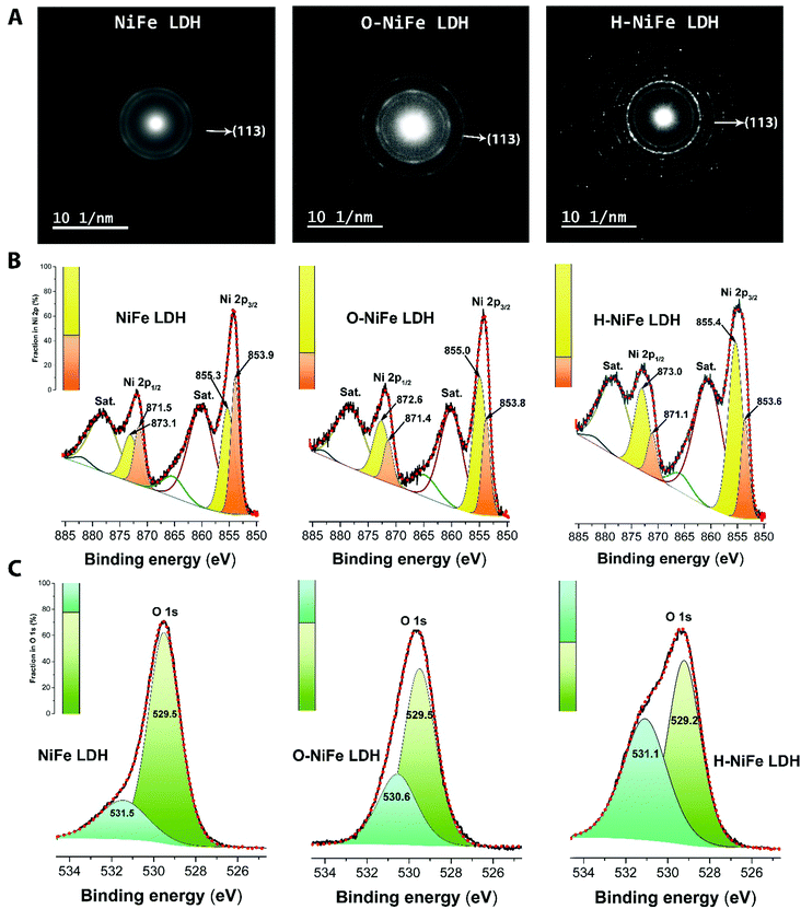
The surface morphology and dispersion of elements also have a decisive effect on the catalytic activity. A series of characterization techniques were used to characterize the surface properties of the catalyst before and after 100 h water electrolysis. Scanning electron microscopy (SEM) images (Fig. 2E–G and Fig. S7A, D and G, ESI†), energy-dispersive X-ray spectroscopy mappings (Fig. S7, ESI†) and X-ray photoelectron spectroscopy (XPS, Fig. S9A, ESI†) showed that there was no obvious change of catalyst surface morphologies and the dispersion of Fe, Ni, and O elements or their relative composition before and after 100 h operation. The slight composition of potassium (Fig. S8 and S9A, ESI†) was from the electrolyte. Transmission electron microscopy (TEM) images (Fig. S7B, E, and H, ESI†) show that the catalysts consist of ultrathin layers, which is beneficial to exposed surface reactive sites. TEM images (Fig. S7C, F and I, ESI†) reveal that the hydrogen evolution reaction contributed to a beneficial crystal restructuring during 100 h testing, manifested as the clear presence of many small crystals. SAED results (Fig. 3A) show the same crystal structure as as-observed XRD pattern (Fig. S10, ESI†) with interplanar distances of 0.15 nm, corresponding to nickel–iron carbonate hydroxide hydrate (113) planes, suggesting that the crystal structure is maintained during aging. It is noteworthy that the sharpness of the ring pattern is increasing markedly from left to right in the first row of Fig. 3A, which reveals an increase in crystallinity during gas evolution. This is also confirmed by photoluminescence (PL) measurements, in which the PL intensity of H-NiFe LDH is much higher than the pristine NiFe LDH and slightly stronger than O-NiFe LDH (Fig. S11, ESI†). The dynamically enhanced crystallinity is here contributing to improved charge and ion transport, which leads to decreased reaction resistance as also seen in the EIS analysis (Fig. S4, ESI†). These mutual effects of each unique structural property result in one of the highest conversion efficiencies from electricity to hydrogen fuel in a non-precious metal oxide catalyst to date.Ex situ X-ray photoelectron spectroscopy (XPS) and electron energy loss spectroscopy (EELS) were performed to give more information about valence states before and after water electrolysis. Fig. 3B shows Ni 2p spectra, which show two spin–orbit peaks with a binding energy difference of ∼18 eV, namely Ni 2p1/2 and Ni 2p3/2 with two shakeup satellites. The Ni 2p1/2 and Ni 2p3/2 spectra were deconvoluted into four peaks, located at ∼853.9, 871.5 eV, ∼855.3, and 873.1 eV. The relative increase of the high-energy peak within the convolution as well as the accompanying broadening of the total peak indicate a slight increase in Ni3+ with respect to Ni2+ for the catalyst after the OER reaction (O-NiFe LDH) and a more pronounced increase in valence after the HER reaction (H-NiFe LDH). For the O 1s spectra, (Fig. 3C), the peak around 529.5 eV can be assigned to lattice oxygen in nickel(II) species36 while the O 1s spectrum peak at a higher energy (∼531 eV) is characteristic for oxygen bound to species with higher valence, here primarily higher valence Ni3+ compounds.37 In addition, the energy of this peak also matches oxygen bound in CO32− in the interlayer.38 As the 531 eV peak is increasing slightly after the OER and more markedly, after the HER, consistent with the Ni 2p satellites, and that the concentration of inter-layer CO32− is not expected to change for a fixed stoichiometry and carbon free electrolyte, both these observations point to a slight increase in the valence for Ni after the OER and a more pronounced valence increase after the HER. As the high energy peak is significantly stronger for H-NiFe LDH, it indicates a correlation between increased valence in nickel in the catalyst and the favorable HER efficiency. The observation of Fe 2p1/2 and Fe 2p3/2 at 724 and 711.6 eV confirms that the dominant Fe species cannot be in the Fe2+ state (Fig. S9B, ESI†). In the O 1s spectra, Fe species bound to oxygen are expected to give contributions to the low energy peak at around 529.5 eV.36 Although the exact energy positions of the peaks discussed above are sensitive to the bonding conditions or phases, especially in oxides and hydroxides, the various integrated areas of the different Ni and O species (Fig. 3B and C) and the variable L3/L2 ratio of Ni and Fe (Fig. S12, ESI†) indicate that the reactive steps under OER and HER in alkaline media are different. The post-mortem measurements cannot, however, certify if the findings represents the prevalent valence of the active phase during increased Fermi-level as an electrocatalysts or represent the depleted phase after the reaction has taken place. So although information of the change in valance from ex situ measurements can be instructive, information is lacking on how the situation is changing when a potential is applied to the anode or the cathode, resulting in the formation of an active catalyst surface layer. Therefore, in situ measurements during the reaction are necessary to thoroughly characterize the catalysts and we now proceed to discuss this subject.
To obtain information about the chemical identities of the active surface layer, Raman spectroscopy was performed. Raman spectroscopy is here a versatile tool that can detect intermediate amorphous states, potential clusters/molecular species, and recrystallization status.39 Raman peaks of initial NiFe LDH were observed at 486, 567 and 699 cm−1 under 532 nm excitation (Fig. S13, ESI†), which agree with previously reported peaks in the Ni–Fe system.40,41 Fourier transform infrared spectroscopy (FT-IR) shows the stretching vibrations of intercalated carbonates in the NiFe LDH at 1337 cm−1 (ν3CO32−)42 and 1053 cm−1 (ν1CO32−)43 (Fig. S14, ESI†). From the various ex situ characterizations, there is a clear difference between pristine NiFe LDH and the aged catalysts operating under the two different reactions (H-NiFe LDH and O-NiFe LDH). In order to probe interfacial active phases of catalysts under the HER and OER reaction conditions, in situ Raman spectro-electrochemistry was performed with controlled electrochemical overpotentials in 1 M KOH aqueous solution. A photo of the in situ Raman experiment setup is given in Fig. S15 (ESI†). The broad feature at ∼1637 cm−1 is attributed to characteristics of water and the Raman peak at around 1066 cm−1 could indicate the presence of intercalated carbonate ions (Fig. 4A and 5A),44 which is well matched with FT-IR analysis (Fig. S14, ESI†). The Raman peak observed at ∼140 cm−1 can be assigned to either Ni or Fe hydroxide species because of overlapping of these bands.45 We found that the active modes between 400 cm−1 and 600 cm−1 are potential dependent, clearly presented in Fig. 4B, 5B, and Fig. S16 (ESI†). Compared with Fig. S16 (ESI†), the bands at 455 and 526 cm−1 under HER process in Fig. 4B could be attributed to metal–oxygen vibrations for Ni(OH)246 and FeOOH (Fe3+),47 respectively. The presence of Fe3+ is consistent with the XPS results. Based on the combination of the XPS and Raman data, the presence of Fe seems to suppresses the electrochemical self-reduction activity of Ni compounds (Fig. 4B and Fig. S16, ESI†), which in turn would promote the dissociation of water (H2O + e− ↔ H + OH−). In addition, two broad vibration features turn up after −150 mV at 550–900 cm−1 (peak at 841 cm−1) and as a broad shoulder below 2000 cm−1 (violet circles, Fig. 4A). The features increase with increasing overpotential and can be assigned to hydrated nickel that has been previously reported to exhibit features at 550–950 cm−1 as well as around 2000 cm−1 and down to 1600 cm−1,48,49 with a more specific peak at 840 cm−1.50 However, multi-bonding, variation in bond angles, and the electrolyte environment is expected to provide a further broadening of the features. The formed species (Had–NiO and OHad–FeO) are then compatible with that the water dissociation step (Volmer reaction) is followed by H adsorption on Ni sites (NiO + H ↔ Had–NiO) and the adsorption of OHad produced by water dissociation on Fe sites (Fig. 4C). The HER kinetics will rely not only on the rate of Had adsorption but also on the rate of electron transfer and the ability to release the species to reactivate the site. The synergetic effect of NiFe compounds serves to optimize the reaction route by enhancing the bond association with Had–NiO and a second hydrogen by the formation of FeOOH without adding too much bonding energy to meet the transition energetic demand for release, showing up as a catalytic improvement for HER.
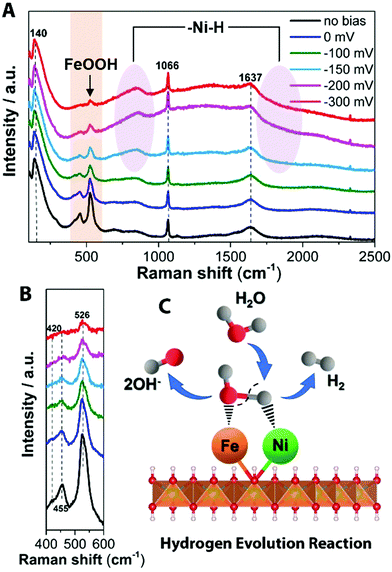 | ||
| Fig. 4 In situ Raman spectrum with 532 nm excitation under HER condition. (A) In situ Raman spectra collected in a large wavenumber region from NiFe LDH during HER process in 1 M KOH at various overpotentials vs. RHE. (B) Magnification of the corresponding orange wavelength region of (A). Schematic illustration (C) showing the reaction mechanism for HER on NiFe LDH. Water from the aqueous electrolyte dissociatively adsorbs on the metal center, forming Had intermediate on the Ni2+ center (Had–NiO), as well as forming OHad intermediate on the Fe3+ center (OHad–FeO), subsequently releasing OH− after accepting the electron. Then hydrogen from a second H2O associates with the NiO and the Had–NiO group and the two adsorbed H combine to form H2. The detailed HER process is shown in the ESI.† | ||
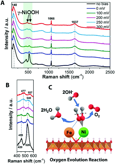 | ||
| Fig. 5 In situ Raman spectrum with 532 nm excitation under OER condition. (A) In situ Raman spectra collected in a large wavenumber region from NiFe LDH during OER process in 1 M KOH at various overpotentials vs. RHE. (B) Magnification of the corresponding green wavelength region of (A). (C) Schematic picture showing the OER mechanism of NiFe LDH. OH− from the aqueous electrolyte is found to adsorb on the Ni2+ center at modest overpotentials (η ∼ 200–300 mV), forming OHad intermediate on the Ni site. The absorbed OH groups react with other such groups to form reaction intermediates that are further oxidized to O2 and H2O, where the OER mechanism has been added into the ESI.† | ||
In water splitting, as is well known, the reaction path of the OER is more complicated than that of the HER, involving more reaction intermediates before O2 evolution. Fig. 5A shows the transformation of Ni(OH)2 to NiOOH with increased overpotential on the surface of NiFe LDH. The observed frequencies of 477 ± 1 and 557 ± 1 cm−1 (Fig. 5B and Fig. S14, ESI†) match well with spectral features of γ-NiOOH where the average oxidation state of Ni is +3.3 to 3.7,51,52 this is beneficial to achieve a high reactivity of OER.53 Raman bands at 477 ± 1 and 557 ± 1 cm−1 were generated from 0 mV overpotential vs. RHE toward water oxidation on Ni(OH)2 (Fig. S16 and its other material characterization results are shown in Fig. S17–S19, ESI†), while, NiFe LDH exhibited a sluggish transition period from Ni(OH)2 to NiOOH at a larger overpotential. This indicates that the presence of Fe in NiFe LDH inhibits the electrochemical oxidation of Ni(OH)2 to NiOOH, consistent with previous suggestions for the half-reaction.40 Additionally, the higher ratio of intensities of two Raman bands of γ-NiOOH and the water molecular vibration in NiFe-based catalyst indicate its highly efficient species transformation, thus resulting in increased gas evolution that in turn scatter light and change the Raman cross section. Based on our observation (Table S2, ESI†), we suggests that at low potentials OHad is adsorbed at Fe sites to form FeOOH on the NiFe LDH electrode whereas at the higher potentials it tends to be absorbed at (or migrated to) Ni sites as revealed by the emerging Raman features of NiOOH. This behavior can be rationalized by realizing that the interaction of OH− with Fe3+ is stronger than with Ni2+, which is consistent with the behavior of Fe3+ as a stronger Lewis acid. At the increased applied potential, the electronic effect of Fe3+ could induce a higher Ni valency, more likely to bond with OH− to accelerate the water dissociation in alkaline electrolyte. Taking into account the Raman spectra data evolving at different overpotentials, the active Ni phase in NiOOH-mediated OER is the high Ni valency-containing γ-NiOOH. As schematically shown in Fig. 5C, the OHad selectively adsorbed on Ni sites to form OHad–Niδ+ and then release O2 by combination steps.
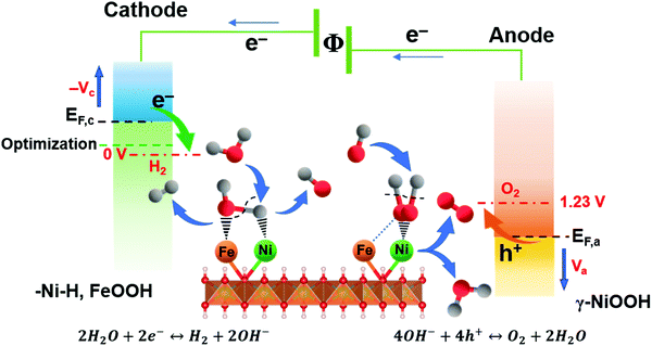
Based on the valence state analysis from ex situ XPS, EELS, the limiting reaction steps from EIS and most importantly the active surface species emerging at different potentials from the in situ Raman data, the overall working mechanism and active surface layers can be summarized (Fig. 6). The results show that Ni and Fe species contribute differently to the catalytic activity at different applied overpotentials at the respective electrodes, forming a synergistic effect beneficial for both the HER and OER reaction and resulting in the most effective bi-functional metal oxide water electrocatalysts to date.
Conclusions
A NiFe LDH system is investigated as a bi-functional catalyst as well as analyzed in detail in terms of the prevailing oxidations states and active surface species formed. Applied as a bi-functional catalyst, the system shows a low OER overpotential and is seen to dynamically self-optimize the active sites, resulting in markedly improved HER activity that outperforms platinum used under the same conditions. The overpotential of HER at 10 mA cm−2 was decreased by 145 mV after the dynamic self-optimization. The activated catalysts show an overpotential of 184 and −59 mV without iR compensation for oxygen evolution reaction (OER) and HER at 10 mA cm−2. Tafel analysis indicate that the HER mechanism was rate determined by the Volmer–Heyrovsky reaction; however, the OER process was controlled by the characteristics of the combination reaction between metal sites and OH. A variety of ex situ techniques and in situ Raman spectro-electrochemistry shows the transformation from original to active catalyst redox phases according to different reaction processes and reveal a synergistic electronic interplay between Fe and Ni in facilitating effective water electrolysis. In particular, presence of Fe has the function to inhibit the Ni self-oxidation and promote water dissociation into H2 under the HER process by the formed FeOOH and Had–Niδ+ species, while γ-NiOOH and higher valance Ni was prevalently created during the OER reaction. The present work shows that dynamically enhanced crystallinity and atomic mutual effects are crucial for high efficiency of NiFe LDH catalysts. The system can be utilized as a low-cost, efficient, and durable bi-functional catalyst, which bears promises for integration into renewable technologies, such as fuel formation from wind- or solar based electricity in alkaline or anion exchange membrane (AEM) electrolyzers for sustainable production of hydrogen or other clean fuels.Author contributions
Z. Qiu conceived the idea, designed and performed the experiments as well as data analysis. C.-W. Tai contributed to the TEM and EELS measurements as well as EELS analysis. G. A. Niklasson supervised the EIS analysis and manuscript writing. Z. Qiu, and T. Edvinsson co-wrote the manuscript. T. Edvinsson performed analysis, supervised, and supported the work.Conflicts of interest
The authors declare no competing interests.Acknowledgements
The Swedish Energy Agency and Swedish Research Council (VR-2016-03713), Swedish Research Council for sustainable development (FORMAS 2016-00908) are acknowledged for their financial support. The Knut and Alice Wallenberg (KAW) Foundation is acknowledged for funding the electron microscopy facilities at the Stockholm University.References
- Z. W. Seh, J. Kibsgaard, C. F. Dickens, I. Chorkendorff, J. K. Nørskov and T. F. Jaramillo, Science, 2017, 355, eaad4998 CrossRef.
- S. Arrhenius, Conférences sur quelques problèmes actuels de la chimie physique et cosmique faites à l'Université de Paris en avril et mai, 1922, impr.-libr.-éditeurs Gauthier-Villars et Cie, 55, quai des Grands-Augustins, 1928.
- D. Larcher and J. M. Tarascon, Nat. Chem., 2015, 7, 19 CrossRef CAS PubMed.
- A. Podder and M. Kapner, Analysis of batteries for use in photovoltaic systems. Final report, Hittman Associates, Inc., Columbia, MD, USA, 1981 Search PubMed.
- J. Cho, S. Jeong and Y. Kim, Prog. Energy Combust. Sci., 2015, 48, 84–101 CrossRef.
- R. W. Coughlin and M. Farooque, Nature, 1979, 279, 301 CrossRef CAS.
- J. M. Carrasco, L. G. Franquelo, J. T. Bialasiewicz, E. Galván, R. C. PortilloGuisado, M. M. Prats, J. I. León and N. Moreno-Alfonso, IEEE Trans. Ind. Electron., 2006, 53, 1002–1016 Search PubMed.
- M. S. Dresselhaus and I. L. Thomas, Nature, 2001, 414, 332 CrossRef CAS PubMed.
- D. Voiry, H. S. Shin, K. P. Loh and M. Chhowalla, Nat. Rev. Chem., 2018, 1, 0105 CrossRef.
- J. D. Holladay, J. Hu, D. L. King and Y. Wang, Catal. Today, 2009, 139, 244–260 CrossRef CAS.
- K. Zeng and D. Zhang, Prog. Energy Combust. Sci., 2010, 36, 307–326 CrossRef CAS.
- R. D. Smith, M. S. Prévot, R. D. Fagan, Z. Zhang, P. A. Sedach, M. K. J. Siu, S. Trudel and C. P. Berlinguette, Science, 2013, 1233638 Search PubMed.
- A. Ursua, L. M. Gandia and P. Sanchis, Proc. IEEE, 2012, 100, 410–426 CAS.
- M. Carmo, D. L. Fritz, J. Mergel and D. Stolten, Int. J. Hydrogen Energy, 2013, 38, 4901–4934 CrossRef CAS.
- D. Pletcher and F. Walsh, Industrial electrochemistry, Blackie Academic & Professional, London, New York, 2nd edn, 1993 Search PubMed.
- B. Zhang, X. Zheng, O. Voznyy, R. Comin, M. Bajdich, M. García-Melchor, L. Han, J. Xu, M. Liu, L. Zheng, A. Vojvodic and E. H. Sargent, Science, 2016, 352, 333–337 CrossRef CAS PubMed.
- F. Dionigi and P. Strasser, Adv. Energy Mater., 2016, 6, 1600621 CrossRef.
- H. Zhong, J. Wang, F. Meng and X. Zhang, Angew. Chem., Int. Ed., 2016, 55, 9937–9941 CrossRef CAS PubMed.
- Z. Qiu, Y. Ma, K. Edström, G. A. Niklasson and T. Edvinsson, Int. J. Hydrogen Energy, 2017, 42, 28397–28407 CrossRef CAS.
- L. Cheng, W. Huang, Q. Gong, C. Liu, Z. Liu, Y. Li and H. Dai, Angew. Chem., Int. Ed., 2014, 53, 7860–7863 CrossRef CAS.
- M. A. Lukowski, A. S. Daniel, F. Meng, A. Forticaux, L. Li and S. Jin, J. Am. Chem. Soc., 2013, 135, 10274–10277 CrossRef CAS PubMed.
- J. Zhang, T. Wang, P. Liu, Z. Liao, S. Liu, X. Zhuang, M. Chen, E. Zschech and X. Feng, Nat. Commun., 2017, 8, 15437 CrossRef CAS PubMed.
- X. B. Zhang, J. Wang, H. X. Zhong, Z. L. Wang and F. L. Meng, ACS Nano, 2016, 10, 2342–2348 CrossRef PubMed.
- J. Zhang, T. Wang, D. Pohl, B. Rellinghaus, R. Dong, S. Liu, X. Zhuang and X. Feng, Angew. Chem., 2016, 128, 6814–6819 CrossRef.
- Y. Hou, M. R. Lohe, J. Zhang, S. Liu, X. Zhuang and X. Feng, Energy Environ. Sci., 2016, 9, 478–483 RSC.
- J. A. Turner, Science, 2004, 305, 972–974 CrossRef CAS PubMed.
- N. Kim, S. Chae, J. Ma, M. Ko and J. Cho, Nat. Commun., 2017, 8, 812 CrossRef PubMed.
- L. Trotochaud, S. L. Young, J. K. Ranney and S. W. Boettcher, J. Am. Chem. Soc., 2014, 136, 6744–6753 CrossRef CAS PubMed.
- S. Klaus, Y. Cai, M. W. Louie, L. Trotochaud and A. T. Bell, J. Phys. Chem. C, 2015, 119, 7243–7254 CrossRef CAS.
- T. Shinagawa, A. T. Garcia-Esparza and K. Takanabe, Sci. Rep., 2015, 5, 13801 CrossRef PubMed.
- J. O. M. Bockris, J. Chem. Phys., 1956, 24, 817–827 CrossRef CAS.
- B. Conway and P. Bourgault, Can. J. Chem., 1962, 40, 1690–1707 CrossRef CAS.
- J. Wang, F. Xu, H. Y. Jin, Y. Q. Chen and Y. Wang, Adv. Mater., 2017, 29, 1605838 CrossRef PubMed.
- J.-P. Diard, B. LeGorrec and S. Maximovitch, Electrochim. Acta, 1990, 35, 1099–1108 CrossRef CAS.
- D. Harrington and B. J. E. A. Conway, Electrochim. Acta, 1987, 32, 1703–1712 CrossRef CAS.
- M. C. Biesinger, B. P. Payne, A. P. Grosvenor, L. W. Lau, A. R. Gerson and R. S. C. Smart, Appl. Surf. Sci., 2011, 257, 2717–2730 CrossRef CAS.
- E. Avendano, H. Rensmo, A. Azens, A. Sandell, G. D. M. Azevedo, H. Siegbahn, G. Niklasson and C. G. Granqvist, J. Electrochem. Soc., 2009, 156, P132–P138 CrossRef CAS.
- Z. Fu, J. Hu, W. Hu, S. Yang and Y. Luo, Appl. Surf. Sci., 2018, 441, 1048–1056 CrossRef CAS.
- S. M. Jain, Z. Qiu, L. Häggman, M. Mirmohades, M. B. Johansson, T. Edvinsson and G. Boschloo, Energy Environ. Sci., 2016, 9, 3770–3782 RSC.
- M. W. Louie and A. T. Bell, J. Am. Chem. Soc., 2013, 135, 12329–12337 CrossRef CAS.
- A. Ahlawat and V. Sathe, J. Raman Spectrosc., 2011, 42, 1087–1094 CrossRef CAS.
- G. Chen, T. Wang, J. Zhang, P. Liu, H. Sun, X. Zhuang, M. Chen and X. Feng, Adv. Mater., 2018, 30, 1706279 CrossRef PubMed.
- C. R. Gordijo, V. R. L. Constantino and D. de Oliveira Silva, J. Solid State Chem., 2007, 180, 1967–1976 CrossRef CAS.
- D. M. Carey and G. M. Korenowski, J. Chem. Phys., 1998, 108, 2669–2675 CrossRef CAS.
- D. Thierry, D. Persson, C. Leygraf, D. Delichere, S. Joiret, C. Pallotta and A. Hugot-Le Goff, J. Electrochem. Soc., 1988, 135, 305–310 CrossRef CAS.
- D. S. Hall, An electrochemical and spectroscopic investigation of nickel electrodes in alkaline media for applications in electro-catalysis, Doctoral dissertation, Université d'Ottawa/University of Ottawa, 2014 Search PubMed.
- M. Hanesch, Geophys. J. Int., 2009, 177, 941–948 CrossRef CAS.
- W. Krasser and A. Renouprez, J. Raman Spectrosc., 1979, 8, 92–94 CrossRef CAS.
- R. Stockmeyer, H. Stortnik, I. Natkaniec and J. Mayer, Ber. Bunsen-Ges., 1980, 84, 79–84 CrossRef CAS.
- J. M. Nicol, Spectrochim. Acta, Part A, 1992, 48, 313–327 CrossRef.
- B. S. Yeo and A. T. Bell, J. Phys. Chem. C, 2012, 116, 8394–8400 CrossRef CAS.
- S. Klaus, Y. Cai, M. W. Louie, L. Trotochaud and A. T. Bell, J. Phys. Chem. C, 2015, 119, 7243–7254 CrossRef CAS.
- X. Zheng, B. Zhang, P. De Luna, Y. Liang, R. Comin, O. Voznyy, L. Han, F. P. G. de Arquer, M. Liu and C. T. Dinh, Nat. Chem., 2018, 10, 149 CrossRef CAS PubMed.
Footnote |
| † Electronic supplementary information (ESI) available. See DOI: 10.1039/c8ee03282c |
| This journal is © The Royal Society of Chemistry 2019 |

