
Enhancing interfacial contact in all solid state batteries with a cathode-supported solid electrolyte membrane framework†
Xinzhi
Chen
a,
Wenjun
He
b,
Liang-Xin
Ding
a,
Suqing
Wang
a and
Haihui
Wang
 *a
*a
aSchool of Chemistry and Chemical Engineering, South China University of Technology, No. 381 Wushan Road, Guangzhou 510640, China. E-mail: hhwang@scut.edu.cn
bGuangzhou FLM Scientific Instrument Co. Ltd, China
First published on 5th November 2018
Abstract
To address the challenge of interfacial contact between the solid electrolyte and electrode with a cost-efficient solution, we demonstrate a novel cathode-supported solid electrolyte membrane framework for advanced all solid state Li ion batteries. The solid electrolyte is directly cast on the cathode layer to enhance the wetting ability of solid electrolyte onto the cathode and reinforce the interfacial adhesion. Results show that the as-fabricated LiFePO4/Li solid state battery displays superior battery performances, e.g., an initial discharge capacity of 125 mA h g−1 at 0.1C at room temperature can be achieved. The proposed electrolyte framework represents a promising strategy for mass production of high performance all solid state batteries based on Li metal anodes.
Broader contextAll solid state rechargeable batteries are promising to meet the challenges of high safety and high energy density for future energy storage, but practical applications have been limited by many challenges including poor interfacial contact, high manufactural cost, and relatively low ionic conductivity at room temperature. However, if we can provide a simple and low cost manufactural approach to fabricate a thin solid electrolyte with enhanced interfacial contact, ionic conductivities of state of the art solid electrolytes, to some extent, could be sufficient enough for high performance solid state rechargeable batteries. Herein, we reported such an approach by introducing a concept of a cathode-supported solid electrolyte membrane, which was realized by a facile tape casting technique. When assembling all solid state lithium ion batteries with such a cathode-supported solid electrolyte membrane and a metal lithium anode, the as fabricated batteries demonstrate superior battery performances than those of conventional solid state lithium ion batteries, and comparable to those of liquid lithium ion batteries. Moreover, since tape casting is a mature industrial technique, the application of such a cathode-supported solid electrolyte membrane could be easily extended to mass production of such high performance solid state batteries. |
Rechargeable batteries, as the most important energy storage and transition device, have been utilized to power most portable electronic devices and electric vehicles and store electricity generated from intermittent renewable sources, such as wind and solar energy.1–4 Additionally, use of rechargeable batteries has also been tried in stationary load-levelling in which inexpensive night-time electricity is stored for use during the daytime.1 Among commercial batteries (such as lead–acid, nickel-metal hydride, lithium ion and flow batteries), lithium ion batteries are most widely used due to their high energy density and long cycle life currently.2,5,6 However, conventional lithium ion batteries (LIB) normally use flammable non-aqueous liquid electrolytes, resulting in a serious safety issue in use. In this respect, all solid state lithium ion batteries (SSLIBs) are regarded as a fundamental solution to address the safety issue by using a solid state electrolyte (SSE) in place of the conventional liquid one.7–9 In addition, since SSEs can suppress Li dendrite formation and normally possess higher electrochemical windows of above 5 V, Li metal anodes and high voltage cathodes could be used in SSLIBs, leading to higher energy densities.4,10,11 In general, SSEs can be categorized into two classes, namely, inorganic solid electrolytes including sulfides and oxides,12,13 and solid polymer electrolytes including PEO, PVDF, PMMA, and PAN based electrolytes.14,15 Inorganic solid electrolytes possess high ionic conductivities, and a high lithium ion transference number (t+Li ≈ 1).16 However, some fatal flaws such as brittleness, manufacturing difficulty and poor interfacial contact between the electrolyte and the electrode make inorganic solid electrolytes difficult to use in practical applications.7,17 On the contrary, solid polymer electrolytes incorporating a polymer matrix with lithium salts seem to be more feasible due to unique advantages of flexibility in the shape of battery design and convenience in manufacturing (e.g., large scale thin electrolyte sheet manufacturing). Further studies discovered that inorganic nanofillers such as TiO2 and Al2O3 can reduce the crystallization of the polymer matrix and hence increase the ionic conductivity of solid polymer electrolytes.14,18,19
The nature of interfacial contact between the electrolyte and the electrode in traditional liquid lithium ion batteries and SSLIBs is quite different (Fig. 1). The liquid electrolytes can wet the electrode well in the former, while the SSE and the electrode are in rigid contact in the latter; this can lead to high interfacial resistances in SSLIBs. Thus, it is significantly important to minimize the interfacial resistance between the SSE and the electrode for the purpose of developing successful SSLIBs. There are already works on minimizing the interfacial impedance in the solid state Li metal batteries based on garnet-based solid electrolytes, e.g., Hu et al. designed a porous supported bilayer garnet structure to minimize the solid state electrolyte impedance.20 Ultrathin Al2O3 was deposited on a garnet-based solid electrolyte by atomic layer deposition to minimize the interfacial impedance in garnet-based solid state Li metal batteries.21 However, a lot of research work concerned maximizing the conductivity in SSEs, but few works focus on minimizing the interfacial resistances of SSE|electrode.10,20,21 Actually, the ion conductivity might be no longer the limiting factor for the application of thin film SSEs. For example, a micro-battery based on a Li|LiPON|LiNi0.5Mn1.5O4 structure with a typical LIPON film thickness of only a few microns was reported by Li et al.,11 while only a low current density of ∼1 μA cm−2 rather than several mA cm−2 which is expected based on the thickness of the LiPON thin film was currently obtained, resulting in a low capacity and low power density.10 Considering that LiPON has only a modest Li+ conductivity, and there are several superionic SSEs with Li+ conductivity much higher than that of LiPON,9,21–27 the Li+ conductivities to some extent could be more than sufficient for high performance SSLIBs if there are no other limiting factors such as interfacial resistance.
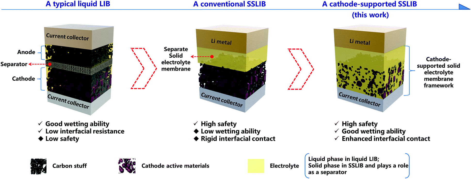 | ||
| Fig. 1 Schematic of the novel cathode-supported SSLIB in comparison with a conventional rigid SSLIB and a typical liquid LIB. Safety issue of LIBs can be resolved by substituting liquid electrolytes with solid electrolyte membranes, however, the low wetting ability of solid electrolytes and the rigid contact between solid electrolyte membranes and electrodes result in high interfacial resistances in conventional SSLIBs. A cathode-supported solid electrolyte membrane framework is designed, where the solid electrolyte is directly cast on the cathode layer to enhance the wetting ability of solid electrolyte onto the cathode and reinforce the interfacial adhesion. | ||
In this work, to enhance the interfacial contact between the SSE and the electrode with a cost-effective solution, we provide a novel strategy to prepare a cathode-supported solid state electrolyte membrane by a facile tape casting method operated in the air, where the solid electrolyte is directly cast on the cathode layer, as shown in Fig. 1. By doing so, at least two advantages can be obtained: (1) reinforcing the interfacial adhesion between the cathode layer and the solid electrolyte membrane, and (2) enhancing the wetting ability of solid electrolyte onto the cathode due to pores inside the cathode being filled by solid electrolyte. PEO based composite solid electrolytes were employed as the model solid electrolyte because of several desired physical and chemical properties, including (1) outstanding compatibility as a solid solvent for a wide range of alkaline salts, (2) good film forming features, and (3) easily obtainable at a low cost. Different from conventional methods to fabricate solid state batteries, it is not necessary to prepare a separate cathode layer and a separate solid electrolyte membrane apart, instead, we can assemble a SSLIB directly combining the cathode-supported solid electrolyte membrane with a metal lithium anode, thus simplifying the fabrication process. For demonstration purpose, all solid state LiFePO4/Li cells were assembled. Remarkably, these SSLIBs can deliver discharge capacities of 125 and 90 mA h g−1 (at 30 °C) at 0.1 and 0.2C, respectively. Besides, discharge capacities of 169, 167, 163, and 137 mA h g−1 (at 50 °C) can be achieved at 0.05, 0.1, 0.24, and 0.5C, respectively. What's more, comparisons of the electrochemical performances of previously reported SSLIBs are shown in Table S1 (ESI†), from which we can see that most SSLIBs based on LiFePO4 cathode material show poor rate capability and capacities.
Fabrication of the cathode-supported solid electrolyte membrane framework
The cathode-supported solid electrolyte membrane framework is prepared by bilayer tape casting. Specifically, a cathode electrode tape was firstly prepared by tape casting (Fig. 2a), then an electrolyte slurry was tape cast onto the cathode electrode tape to form a cathode-supported solid electrolyte membrane after removing the solvent (Fig. 2b). Two PEO-based solid electrolytes (denoted as PAL and PPAL solid electrolytes, a specific description of the electrolytes is present in ESI†) are employed in this study, and further details of the fabrication process are given in the experimental section in ESI.† Since the PEO based solid electrolytes are not sensitive to air and moisture, the PEO based solid electrolyte membrane can be fabricated with a low cost tape casting method. Fig. 2a shows the digital image of the dry cathode electrode tape. The roughness of the tape can be observed from the matt surface. The cathode-supported solid electrolyte membrane after drying is shown in Fig. 2b. The shiny surface suggests that the cathode-supported solid electrolyte membrane is smooth. A schematic of the cathode-supported solid electrolyte membrane framework is shown in Fig. 2a and b. The cathode electrode is full of pores that are formed by random packing of active materials and other additives. The pores inside the cathode layer are filled by the solid electrolyte, leading to a good wetting ability of solid electrolyte onto the cathode. Besides, the interfacial adhesion between the cathode layer and the solid electrolyte membrane is enhanced due to capillary attraction. It is noted that no obvious contamination (Fig. S7 and S8, ESI†) was found in the dry cathode tape owing to the strict quality control process.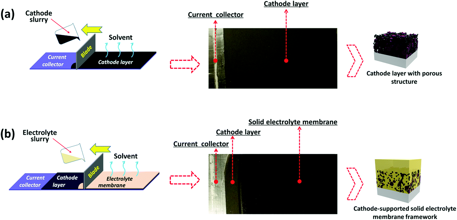 | ||
| Fig. 2 Fabrication of the cathode-supported solid electrolyte membrane framework. (a) Schematic of the cathode electrode preparation by tape casting, the cathode slurry was tape cast on the aluminium current collector. (b) Schematic of the cathode-supported solid electrolyte membrane preparation by tape casting, the electrolyte slurry was tape cast onto the dry cathode tape showing compact structure after drying. | ||
Characterization of the cathode-supported solid electrolyte membrane framework
Detailed morphologies of as obtained cathode-supported solid electrolyte membranes were characterized by scanning electron microscopy (SEM), as shown in Fig. 3 and Fig. S9 (ESI†). The solid electrolyte membrane exhibits a dense and smooth surface (Fig. 3c and Fig. S9a, ESI†). The cathode layer shows a typical morphology of cast electrodes which is homogeneous and porous (Fig. 3b and Fig. S9b, ESI†). The cross section images (Fig. 3a and Fig. S9c, ESI†) indicate that the current collector, the cathode layer and the solid electrolyte layer are well integrated without any visible delamination. Normally, the contact between the cathode and the solid electrolyte is rigid in conventional SSLIBs, leading to poor Li+ transport and high interfacial resistance. In this study, it is difficult to distinguish the interfacial layer from the SEM image in Fig. 3a and Fig. S9c (ESI†), indicating a good contact between the cathode and the solid electrolyte. Furthermore, EDS mapping demonstrates that the thicknesses of the cathode layer and the solid electrolyte layer are around 11.2 and 9.5 μm, respectively (Fig. 3d, the element Al and Fe belong to the Al foil current collector and LiFePO4 cathode, respectively). The thickness of the Al foil is 15.7 μm, which is consistent with the measured result using a micrometer. The tight contact between the cathode and the electrolyte can facilitate reduction of the interfacial resistance, and enhance the Li+ transport through the solid state battery. Therefore, good battery performances can be expected.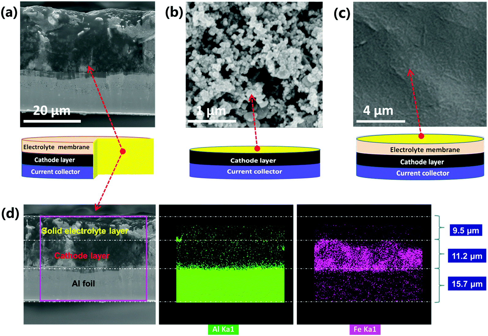 | ||
| Fig. 3 (a) SEM image of the cross section of the cathode-supported PPAL solid electrolyte membrane. (b) Surface morphology of the LiFePO4 cathode layer. (c) Surface morphology of the PPAL solid electrolyte membrane. (d) EDS maps of Al and Fe in the cross section of the cathode-supported PPAL solid electrolyte membrane. | ||
The phase transition evolution of PAL and PPAL solid electrolytes was investigated by in situ XRD measurements conducted in the temperature range of 30 °C to 60 °C (Fig. S2, ESI†). The results show that there is a phase transition occurring at around 50 °C for the PAL solid electrolyte, and the PPAL solid electrolyte always displays an amorphous state from ambient temperature to 60 °C. The differential scanning calorimetry (DSC) results (Fig. S3d, ESI†) confirmed that a phase transition may occur at around 53 °C for the PAL solid electrolyte, while no obvious phase transition can be found for the PPAL solid electrolyte from 30 to 60 °C.
Linear sweep voltammograms (LSV) were measured to determine the electrochemical stability window by sandwiching the solid electrolyte membrane between a Li metal electrode and a stainless steel electrode. PAL and PPAL solid electrolytes start to decompose due to oxidation beyond 5.08 V and 4.55 V (Fig. S3a, ESI†), respectively. Since the cut off voltage of LiFePO4/Li batteries is 3.0 V (discharge) and 3.8 V (charge), thus the PAL and PPAL solid electrolyte membranes are stable enough in the LiFePO4/Li battery system. The thermogravimetric analysis shows that thermal degradation temperatures of PAL and PPAL solid electrolyte membranes are about 381 and 351 °C, respectively, suggesting that the two solid electrolytes are thermally stable to be used in SSLIBs under normal working conditions.
The ionic conductivities of solid electrolytes were investigated via AC impedance spectroscopy measurements by sandwiching the solid electrolyte membrane between two stainless steel blocking electrodes (Fig. S4 and S5, ESI†). The temperature dependence of the ionic conductivity for PAL and PPAL solid electrolyte membranes is shown in Fig. S6 (ESI†). The PAL solid electrolyte shows a lower ionic conductivity than that of the PPAL solid electrolyte at the low temperature region. With increasing the temperature, the ionic conductivity of the PAL solid electrolyte increases faster than that of the PPAL solid electrolyte before approaching 50 °C. The ionic conductivity of the PAL solid electrolyte becomes higher than that of the PPAL solid electrolyte when the temperature passes 50 °C. Arrhenius plots of PAL and PPAL solid electrolyte membranes are shown in Fig. S3b (ESI†). For the PAL solid electrolyte, the activation energy in the low temperature region (30–50 °C) is 79.8 kJ mol−1, and the activation energy in the high temperature region (50–80 °C) is 34.1 kJ mol−1. This difference might be due to the amorphization of PEO from a crystalline state to an amorphous state when it is heated to the phase transition temperature at around 50 °C.28–31 On the contrary, the PPAL solid electrolyte always remains in an amorphous state from ambient temperature to 80 °C; the activation energy is 32.5 kJ mol−1, which is comparable to the activation energies of the PAL solid electrolyte in the high temperature region (50–80 °C). This result implies that Li ion transport through the amorphous electrolyte membrane is much faster than that of the crystalline electrolyte membrane.
Electrochemical characterization of cathode-supported SSLIBs
The electrochemical stability of the as prepared solid electrolyte membrane with Li metal was evaluated by using a symmetric cell. As shown in Fig. S10 (ESI†), the result demonstrates that the symmetric cell exhibits a stable Li plating/stripping process at various current densities. To evaluate and compare electrochemical performances of cathode-supported SSLIBs and conventional SSLIBs (schematically shown in Fig. 1), coin type cells with PPAL and PAL solid electrolytes were assembled in a glovebox. Additionally, liquid batteries with the same cathode and commercial liquid electrolyte were also assembled. The as assembled coin cells were galvanostatically charged and discharged between 3.0 and 3.8 V at 30 and 50 °C with different current rates, the detailed testing programs are shown in Fig. S11 (ESI†). Typical charge–discharge curves of as assembled SSLIBs based on PPAL and PAL solid electrolytes are shown in Fig. 4 and Fig. S12 (ESI†), respectively. As shown in Fig. 4a, the conventional SSLIB based on the PPAL solid electrolyte can only achieve discharge capacities of 20 and 7 mA h g−1 at current rates of 0.1 and 0.2C at 30 °C, respectively. While the cathode-supported SSLIB based on the PPAL solid electrolyte can deliver discharge capacities of 125, 90 and 14 mA h g−1 at current rates of 0.1, 0.2 and 0.5C at 30 °C, respectively. During charge and discharge cycling, high Coulombic efficiency and high capacity retention of 78% after 410 cycles (initial 125 mA h g−1, 110th 115 mA h g−1, 210th 101 mA h g−1, and 410th 98 mA h g−1, at 0.1C) were obtained as seen from Fig. S14 (ESI†), indicating that the cathode-supported solid electrolyte membrane can sustain stable cycling at 30 °C. With increasing the testing temperature to 50 °C, both the conventional SSLIB and the cathode-supported SSLIB deliver higher capacities. Clearly, capacities of the cathode-supported SSLIB are larger than those of the conventional SSLIB at every corresponding current rate (Fig. 4b). As for SSLIBs based on the PAL solid electrolyte, the conventional SSLIB almost delivers no capacity at 30 °C (Fig. S12c, ESI†), while the cathode-supported SSLIB can still deliver capacities of 42, 35 and 20 mA h g−1 at current rates of 0.05, 0.1 and 0.24C, respectively (Fig. S12a, ESI†). When heating SSLIBs to 50 °C, discharge capacities of 155, 145, and 114 mA h g−1 are obtained at current rates of 0.05, 0.1 and 0.24C for the conventional SSLIB (Fig. S12d, ESI†). Remarkably, the cathode-supported SSLIB can deliver discharge capacities of 169, 167, 163, 137 and 36 mA h g−1 at current rates of 0.05, 0.1, 0.24, 0.5 and 1C, respectively (Fig. S12b, ESI†), which are comparable to the battery performance of a typical liquid LIB using the same cathode at 30 °C (Fig. S15, ESI†). These results demonstrate a significant improvement with respect to the specific capacity by using a cathode-supported solid electrolyte membrane framework; it can thus be concluded that the battery performance can be significantly improved by an optimum battery structure without changing the ionic conductivity.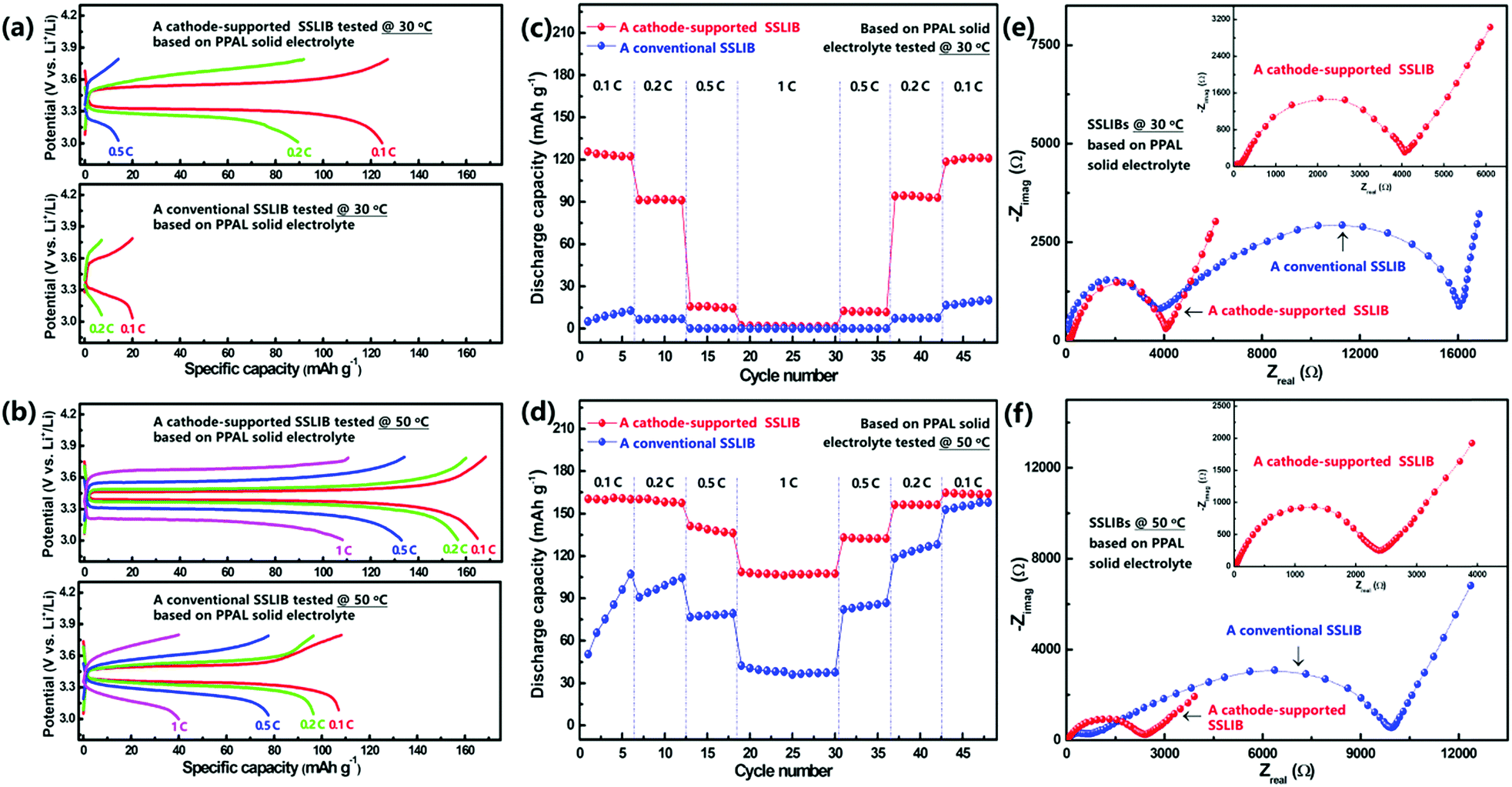 | ||
| Fig. 4 Typical charge–discharge curves of as assembled cathode-supported and conventional SSLIBs based on the PPAL solid electrolyte tested at 30 °C (a) and 50 °C (b). Discharge capacities of conventional and cathode-supported SSLIBs based on the PPAL solid electrolyte tested at 30 °C (c) and 50 °C (d) as a function of cycle number at various rates. Electrochemical impedance plots of a conventional SSLIB and a cathode-supported SSLIB based on the PPAL solid electrolyte at 30 °C (e) and 50 °C (f). | ||
Fig. 4c and d (Fig. S13a and b, ESI†) show a comparison of the rate capability of the conventional and the cathode-supported SSLIBs assembled with PAL and PPAL solid electrolyte membranes at 30 and 50 °C. Discharge capacities decrease as the current rate increases, which might be associated with the polarization. It can be seen that discharge capacities of cathode-supported SSLIBs are larger than those of conventional SSLIBs for all C rates tested. This superior rate capability can be ascribed to the lower interfacial resistance due to the tight interfacial contact between the electrode and the solid electrolyte in cathode-supported SSLIBs. The discharge capacities tested at 50 °C are found to be higher than those of discharge capacities tested at 30 °C, which are caused by the low polarization due to the decrease of the internal resistance and the enhanced lithium ion diffusivity in SSLIBs. Since the PPAL solid electrolyte shows higher ionic conductivities than that of the PAL solid electrolyte in the low temperature region (Fig. S3b and S6, ESI†), correspondingly, SSLIBs based on the PPAL solid electrolyte (Fig. 4c) deliver higher capacities than those of SSLIBs based on the PAL solid electrolyte (Fig. S13a, ESI†) at 30 °C. However, ionic conductivities of the PAL solid electrolyte become higher than the PPAL solid electrolyte in the high temperature region (Fig. S3b and S6, ESI†), thus it is reasonable to find that SSLIBs based on the PAL solid electrolyte (Fig. S13b, ESI†) show relatively higher capacities than those of SSLIBs based on the PPAL solid electrolyte (Fig. 4d) at 50 °C.
Besides the advantage in safety issues, the other unique advantage of solid state batteries is their stackable feature, which leads to a higher output voltage and thus a higher energy density. To visually demonstrate the unique stackable advantage of all solid state batteries, a battery pack made of 2 or 3 SSLIB units was assembled and integrated in a coin type cell. As shown in Fig. 5, the VOCs (voltage of open circuit) of a SSLIB unit, 2 SSLIB units and 3 SSLIB units are 3.08, 6.51, and 9.12 V, respectively. Note that a commercial LED can be lit by all as fabricated SSLIBs.
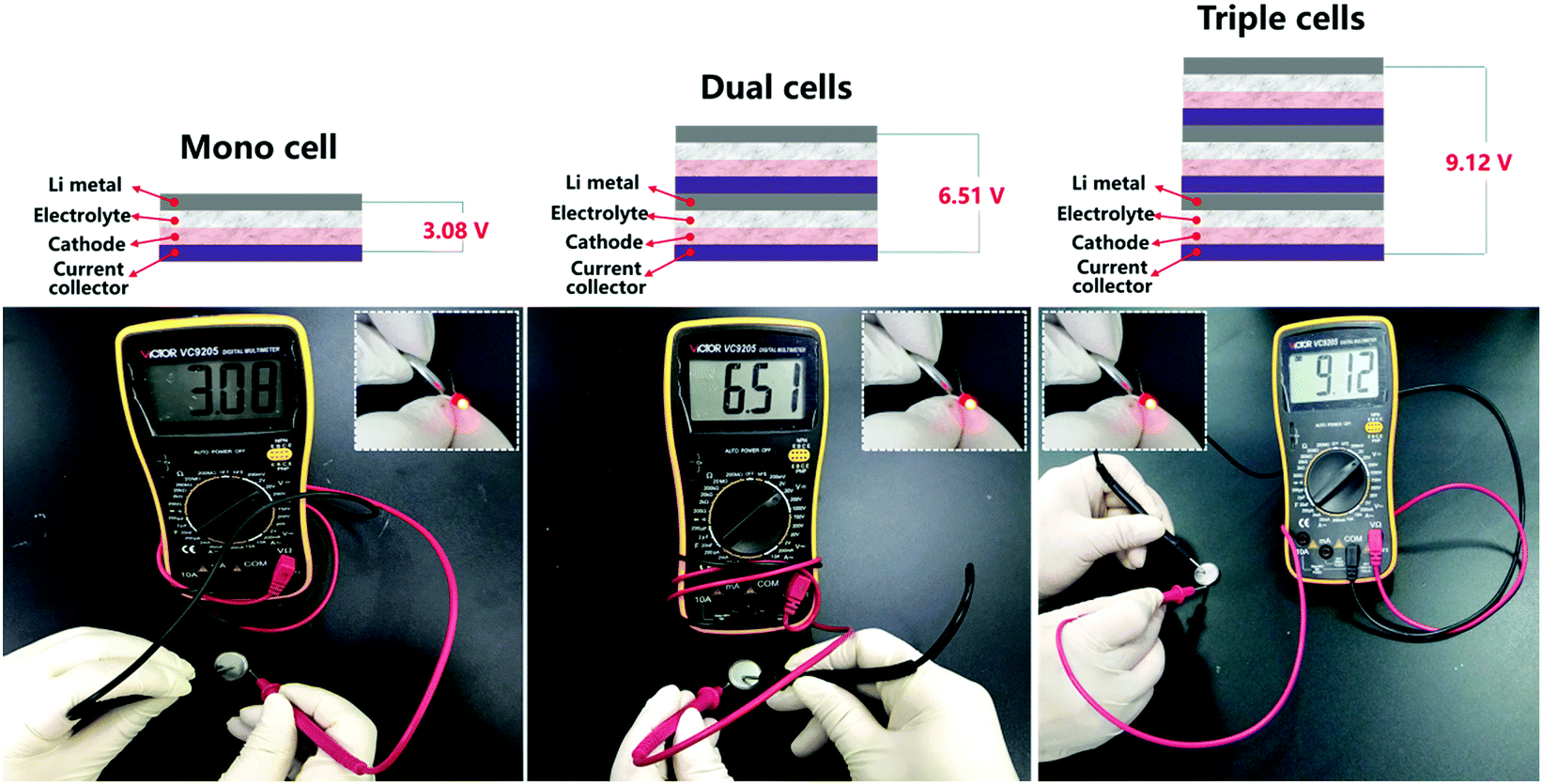 | ||
| Fig. 5 A cathode-supported SSLIB showing a VOC of 3.08 V, a battery pack made by two cathode-supported SSLIBs showing a VOC of 6.51 V, and a battery pack made by three cathode-supported SSLIBs showing a VOC of 9.12 V. All mono/dual/triple cells can power LED light. | ||
Proof-of-concept all solid state Li ion batteries with the cathode-supported solid electrolyte membrane framework
The improvement of discharge capacities and cycle performances by using a cathode-supported solid electrolyte membrane can be understood by the enhancement of the interfacial contact. As shown in Fig. S16a (ESI†), the conventional SSLIB is assembled with a separate solid electrolyte membrane and a separate cathode layer, resulting in two serious problems: (1) there are plenty of pores inside the cathode layer deriving from the evaporation of the solvent during drying, and (2) the interfacial contact between the cathode layer and the solid electrolyte membrane is rigid. Due to the above issues, the active materials in the cathode layer cannot be wet by the solid electrolyte, blocking the ionic conducting channel. However, as shown in Fig. S16b (ESI†), the cathode and the solid electrolyte can be integrated in a cathode-supported solid electrolyte membrane framework, where the pores inside the cathode layer are filled by the solid electrolyte, and the interfacial adhesion between the cathode layer and the solid electrolyte layer is enhanced due to the capillary attraction. As shown in Fig. 3d and Fig. S9c (ESI†), the observations from the SEM images are consistent with our discussion.To further verify the improvement of the interfacial contact by using a cathode-supported solid electrolyte membrane to substitute a separate solid electrolyte membrane, electrochemical impedance spectroscopy was conducted under frequencies from 106 to 10−2 Hz with an oscillation voltage of 5 mV applied to LiFePO4/solid electrolyte/Li cells at 30 and 50 °C, respectively. As shown in Fig. 4e, the overall impedance of a SSLIB with a separate PPAL solid electrolyte membrane at 30 °C is extremely high, resulting in poor battery performance (Fig. 4a). By substituting the separate solid electrolyte membrane with a cathode-supported solid electrolyte membrane, the overall impedance is significantly reduced by an order of magnitude, thus specific capacities of above 120 mA h g−1 can be obtained at 0.1C rate (Fig. 4a). With increasing the temperature to 50 °C, overall impedances of both the conventional SSLIB and the cathode-supported SSLIB reduce a lot, leading to the improvement of battery performances (Fig. 4b). Clearly, the overall impedance of the cathode-supported SSLIB is lower than that of the conventional SSLIB, thus specific capacities of the cathode-supported SSLIB are higher than those of the conventional SSLIB at each corresponding current rate (Fig. 4c and d). Analogous results were also found for SSLIBs based on the PAL solid electrolyte.
Conclusions
In summary, a novel concept of a cathode-supported solid state electrolyte membrane framework was proposed and realized with a facile tape casting technique. It was found that the as prepared cathode-supported solid electrolyte membrane can significantly improve the interfacial contact between the cathode and the solid electrolyte by enhancing the wetting ability of solid electrolyte onto the cathode and reinforcing interfacial adhesion. All solid state lithium ion batteries directly made of the as prepared cathode-supported solid electrolyte membrane and a metal lithium anode deliver superior battery performances than those of conventional solid state lithium ion batteries that employ a separate solid state electrolyte membrane. Remarkably, as fabricated LiFePO4/Li cathode-supported all solid state lithium ion batteries can deliver discharge capacities of 125 (0.1C rate) and 167 (0.1C rate) mA h g−1 at 30 and 50 °C, respectively. Stable cycling over 410 cycles with only slight performance decay was demonstrated. The present work demonstrates a novel but easy to scale up concept for fabricating a cathode-supported solid electrolyte membrane by employing a cost-effective technology; thereby it is very promising to advance the mass production of high performance all solid state lithium ion batteries.Conflicts of interest
There are no conflicts of interest to declare.Acknowledgements
This work was supported by National Key R&D Program (2016YFA0202601).Notes and references
- S. Chu and A. Majumdar, Nature, 2012, 488, 294 CrossRef CAS PubMed.
- J. M. Tarascon and M. Armand, Nature, 2001, 414, 359 CrossRef CAS PubMed.
- J. Cabana, L. Monconduit, D. Larcher and M. R. Palacín, Adv. Mater., 2010, 22, E170 CrossRef CAS PubMed.
- A. Manthiram, X. Yu and S. Wang, Nat. Rev. Mater., 2017, 2, 16103 CrossRef CAS.
- P. G. Bruce, B. Scrosati and J. M. Tarascon, Angew. Chem., Int. Ed., 2008, 47, 2930 CrossRef CAS PubMed.
- V. Etacheri, R. Marom, R. Elazari, G. Salitra and D. Aurbach, Energy Environ. Sci., 2011, 4, 3243 RSC.
- P. Knauth, Solid State Ionics, 2009, 180, 911 CrossRef CAS.
- J. W. Fergus, J. Power Sources, 2010, 195, 4554 CrossRef CAS.
- E. Quartarone and P. Mustarelli, Chem. Soc. Rev., 2011, 40, 2525 RSC.
- A. C. Luntz, J. Voss and K. Reuter, J. Phys. Chem. Lett., 2015, 6, 4599 CrossRef CAS PubMed.
- J. Li, C. Ma, M. Chi, C. Liang and N. J. Dudney, Adv. Energy Mater., 2015, 5, 1401408 CrossRef.
- L. Yue, J. Ma, J. Zhang, J. Zhao, S. Dong, Z. Liu, G. Cui and L. Chen, Energy Storage Mater., 2016, 5, 139 CrossRef.
- E. Kobayashi, L. S. Plashnitsa, T. Doi, S. Okada and J.-i. Yamaki, Electrochem. Commun., 2010, 12, 894 CrossRef CAS.
- A. Manuel Stephan and K. S. Nahm, Polymer, 2006, 47, 5952 CrossRef.
- F. Croce, G. B. Appetecchi, L. Persi and B. Scrosati, Nature, 1998, 394, 456 CrossRef CAS.
- M. Kotobuki and K. Kanamura, Ceram. Int., 2013, 39, 6481 CrossRef CAS.
- Z. Jiang, H. Xie, S. Wang, X. Song, X. Yao and H. Wang, Adv. Energy Mater., 2018, 1801433 CrossRef.
- W. Liu, S. W. Lee, D. Lin, F. Shi, S. Wang, A. D. Sendek and Y. Cui, Nat. Energy, 2017, 2, 17035 CrossRef CAS.
- F. Capuano, J. Electrochem. Soc., 1991, 138, 1918 CrossRef CAS.
- K. Fu, Y. Gong, G. T. Hitz, D. W. McOwen, Y. Li, S. Xu, Y. Wen, L. Zhang, C. Wang, G. Pastel, J. Dai, B. Liu, H. Xie, Y. Yao, E. D. Wachsman and L. Hu, Energy Environ. Sci., 2017, 10, 1568 RSC.
- X. Han, Y. Gong, K. Fu, X. He, G. T. Hitz, J. Dai, A. Pearse, B. Liu, H. Wang, G. Rubloff, Y. Mo, V. Thangadurai, E. D. Wachsman and L. Hu, Nat. Mater., 2017, 16, 572 CrossRef CAS PubMed.
- N. Kamaya, K. Homma, Y. Yamakawa, M. Hirayama, R. Kanno, M. Yonemura, T. Kamiyama, Y. Kato, S. Hama, K. Kawamoto and A. Mitsui, Nat. Mater., 2011, 10, 682 CrossRef CAS PubMed.
- K. H. Park, D. Y. Oh, Y. E. Choi, Y. J. Nam, L. Han, J. Y. Kim, H. Xin, F. Lin, S. M. Oh and Y. S. Jung, Adv. Mater., 2016, 28, 1874 CrossRef CAS PubMed.
- M. H. Braga, A. J. Murchison, J. A. Ferreira, P. Singh and J. B. Goodenough, Energy Environ. Sci., 2016, 9, 948 RSC.
- J. Han, J. Zhu, Y. Li, X. Yu, S. Wang, G. Wu, H. Xie, S. C. Vogel, F. Izumi, K. Momma, Y. Kawamura, Y. Huang, J. B. Goodenough and Y. Zhao, Chem. Commun., 2012, 48, 9840 RSC.
- R. Murugan, V. Thangadurai and W. Weppner, Angew. Chem., Int. Ed., 2007, 46, 7778 CrossRef CAS PubMed.
- Z. Liu, W. Fu, E. A. Payzant, X. Yu, Z. Wu, N. J. Dudney, J. Kiggans, K. Hong, A. J. Rondinone and C. Liang, J. Am. Chem. Soc., 2013, 135, 975 CrossRef CAS PubMed.
- J.-H. Choi, C.-H. Lee, J.-H. Yu, C.-H. Doh and S.-M. Lee, J. Power Sources, 2015, 274, 458 CrossRef CAS.
- Y. Zhao, C. Wu, G. Peng, X. Chen, X. Yao, Y. Bai, F. Wu, S. Chen and X. Xu, J. Power Sources, 2016, 301, 47 CrossRef CAS.
- S. K. Fullerton-Shirey and J. K. Maranas, J. Phys. Chem. C, 2010, 114, 9196 CrossRef CAS.
- R. Prasanth, N. Shubha, H. H. Hng and M. Srinivasan, J. Power Sources, 2014, 245, 283 CrossRef CAS.
Footnote |
| † Electronic supplementary information (ESI) available. See DOI: 10.1039/c8ee02617c |
| This journal is © The Royal Society of Chemistry 2019 |