 Open Access Article
Anionic and neutral 2D indium metal–organic frameworks as catalysts for the Ugi one-pot multicomponent reaction†
Daniel
Reinares-Fisac
,
Lina M
Aguirre-Díaz
 ,
Marta
Iglesias
 ,
Enrique
Gutiérrez-Puebla
 ,
Felipe
Gándara
 * and
M. Ángeles
Monge
 *
*
Departamento de Nuevas Arquitecturas en Química de Materiales, Materials Science Factory, Instituto de Ciencia de Materiales de Madrid (ICMM-CSIC), Sor Juana Inés de la Cruz 3, Cantoblanco 28049, Madrid, Spain. E-mail: amonge@icmm.csic.es; gandara@icmm.csic.es
First published on 5th February 2019
Abstract
Two metal–organic frameworks (MOFs) made of indium and 1,3,5-tris(4-carboxyphenyl)benzene (H3btb) and having a layered structure have been synthesized under solvothermal conditions: [In(btb)(H2O)(DMF)]·L (InPF-50) and [In2(btb)2Cl2]2−·[(CH3)2NH2]22+·L (InPF-51). The structures of both materials have been determined by single crystal X-ray diffraction. The synthetic study which has been carried out demonstrates the influence of the selected indium salt in obtaining each MOF. The structure of both materials consists of pairs of catenated layers, where the metal atoms display coordinated solvent ligands that provide potential open metal sites. The accessibility to these sites along with the presence of Lewis basic sites in the form of uncoordinated oxygen atoms make InPF-50 and -51 efficient catalysts for the four-component Ugi reaction. We attribute this high activity not only to the presence of both acid and basic sites, but also to their convenient locations in the MOF structures. This is further supported by the comparison with [In3O(btb)2(HCO2)]·L, InPF-110, a highly porous indium MOF that only displays Lewis acid sites, and shows lower activity.
Introduction
Metal–organic frameworks (MOFs) constitute a class of reticular materials, built up by the combination of metal cations and organic linkers to form extended, crystalline structures.1 The huge range of possible combinations of metal elements2 and organic linkers,3 and their structural variability, make MOFs very versatile materials with application in an extensive variety of fields, such as catalytic applications,4 gas and hydrocarbon storage5,6 and separation,7–10 electronic sensors11,12 and water capture13,14 and adsorption,15 among others.16–19The use of MOFs in heterogeneous catalysis is particularly interesting as it is possible to attain different metal coordination environments in active solids, thus being possible to modify the activity and selectivity of the resulting catalysts towards a desired reaction.20 In this sense, the marked Lewis acid character of indium, and its variable coordination number make indium MOFs suitable heterogeneous catalyst of adjustable activity.21–24 Over the years, we have been working in this direction by synthesizing a number of 2D and 3D indium based MOFs with catalytic activity in a range of organic reactions,25,26 and investigating the influence of the structural features of the MOFs on the activity.27 Thus, in previous works we demonstrated that the activity of indium MOFs as heterogeneous catalysts in multi-component reactions (MCRs) involving the interaction of multiple substrates in one pot is strongly influenced by the metal cation coordination environment, and the presence of basic Lewis sites in the MOF structure. Following with our structure–activity studies, we have developed two new indium MOFs as efficient heterogeneous catalysts in the one-pot four-component Ugi reaction (Scheme 1). These two materials are denoted InPF-50 [In(btb)(H2O)(DMF)]·L, and InPF-51, [In2(btb)2Cl2]2−·[(CH3)2NH2]22+·L (H3btb = 1,3,5-tris(4-carboxyphenyl)benzene acid, L = solvent: ethanol, water or methanol), and both of them exhibit highly related two-periodic, layered structures.
Experimental details
Materials and methods
All reagents and solvents employed were commercially available and used as received without further purification: In(NO3)3·xH2O (99.999%-In PURATREM from Strem Chemicals); InCl3·4H2O (Alfa Aesar); In(OAc)3 (99.99%-In PURATREM from Strem Chemicals); indium fluoride hydrate (from Abcr); 1,3,5-tris(4-carboxyphenyl)benzene [H3btb] (Strem Chemicals); N,N-dimethylformamide (DMF; Sharlab) and nitric acid 69.5% reagent grade (Sharlab).Powder X-ray diffraction (PXRD) patterns were measured with a Bruker D8 diffractometer with a copper source operated at 1600 W, with step size = 0.02° and exposure time = 0.5 s per step. PXRD measurements were used to check the purity of the obtained microcrystalline products by a comparison of the experimental patterns with the ones calculated from single-crystal X-ray diffraction data. IR spectra were recorded from KBr pellets in the range 4000–400 cm−1 on a Nicolet FT-IR 20SXC spectrometer. Thermogravimetric and differential thermal analysis (TGA-DTA) was performed using a SDT Q600 from TA Instruments equipment in a temperature range between 30 and 800 °C in air (10 mL min−1 flow) atmosphere and heating rate of 10 °C min−1. A CNH PERKIN ELMER 2400 analyzer was employed for the elemental analysis. NMR spectra were recorded in a Bruker AMX-300 equipment using CDCl3 as solvent. Exact mass measurements were performed in an ABSciex QSTAR equipment employing “Electrospray ionization” (ESI) method.
![[double bond, length as m-dash]](https://www.rsc.org/images/entities/char_e001.gif) O), 1547 and 1517 ν(C
O), 1547 and 1517 ν(C![[double bond, length as m-dash]](https://www.rsc.org/images/entities/char_e001.gif) C), 1404 ν(C–C), 1166, 1098, 1020, 879, 848, 818 ν(aromatic C–C), 787 and 708 ν(C–C), 469 ν(In–O).
C), 1404 ν(C–C), 1166, 1098, 1020, 879, 848, 818 ν(aromatic C–C), 787 and 708 ν(C–C), 469 ν(In–O).
![[double bond, length as m-dash]](https://www.rsc.org/images/entities/char_e001.gif) O), 1521, 1380 and 1245 ν(C–O), 1410 ν(C–C), 1175, 1104, 1024, 883, 852, 832 and 711 ν(C–C) aromatic, 782 and 671 ν(C–C), 489 ν(In–O).
O), 1521, 1380 and 1245 ν(C–O), 1410 ν(C–C), 1175, 1104, 1024, 883, 852, 832 and 711 ν(C–C) aromatic, 782 and 671 ν(C–C), 489 ν(In–O).
Results and discussion
During the preparation of the previously reported material InPF-110, we found the appearance of a competitive phase, [In(btb)(H2O)(DMF)]·L, denoted InPF-50. Optimization of the synthetic conditions has now led us to the synthesis of this new MOF as pure phase, as proved by powder X-ray diffraction (PXRD). Once the MOF was characterized, a systematic study with different indium salts was performed, by using the Cl−, CH3COO−, NO3−, and F− anions. We found that the later three drove to the formation of InPF-50 crystals with a variety of crystalline habits, such as columnar and prismatic or striated tabular crystals (Fig. 1 and 2). When using the highly coordinative chloride anion, InPF-51 was obtained (Fig. 2), finding that in this case the anion remained coordinated to the metal atoms in the MOF structure.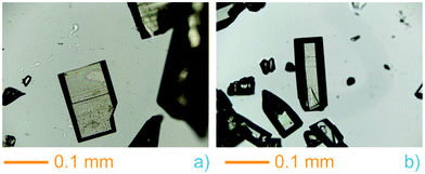 | ||
| Fig. 1 InPF-50 prismatic and tabular crystals obtained with indium nitrate (a) and columnar with obtained with indium acetate (b). | ||
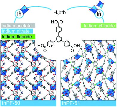 | ||
| Fig. 2 InPF-50 and -51 are built by organic linker H3btb and one kind of indium environment monomeric SBU in the case of InPF-50, and two kinds of environment in the case of InPF-51. | ||
Structural description
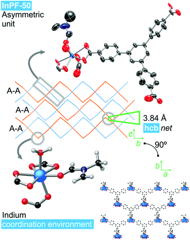
Single crystal X-ray diffraction analysis of InPF-50 indicates that the compound crystallizes in the orthorhombic system, space group Pbcn, with lattice parameters a = 17.5574(8) Å, b = 20.8944(9) Å and c = 16.8168(8) Å (see ESI Table S2.1†). The structure of InPF-50 consists of an inorganic SBU formed by just one seven-coordinated indium cation. This indium cation is coordinated to three carboxylate groups from btb3− linkers, two of them in a chelating trans position and the third one, in cis position is linked through a η1 carboxylate oxygen atom. The seventh position is occupied by a DMF molecule (Fig. 3). These weaker coordinated DMF molecules can be easily replaced by other solvents, leaving accessible open metal sites.The inorganic SBUs are connected through the tritopic linker to form hcb layers with a wave-like shape. These layers are catenated in pairs, and stacked along the c axis, with an interlayer distance between non-catenated layers of 3.84 Å, as a result of π–π interactions among each pair of sheets (measured between the centroid of the overlapped central phenyl rings of the linkers, Fig. 3). A sparse pore appears up and down every couple of π–π interacting rings. These pores are filled with solvent DMF molecules coordinated to the indium cations.
InPF-51. Single crystal X-ray diffraction analysis indicates that the compound crystallizes in the monoclinic system, space group P21/n, with lattice parameters a = 17.3589(6) Å, b = 13.0410(6) Å, c = 25.9082(9) Å and β = 91.109(2)°. Overall, the structure is highly related to the previously described InPF-50, showing inorganic SBUs consisting of indium atoms connected through the btb3− linker to form waved hcb layers, which are also catenated in pairs. Pairs of catenated layers stack along the crystallographic b axis. In this case the distance between non-catenated layers is shorter than that of InPF-50 (π–π interaction of 3.66 Å, Fig. 4).
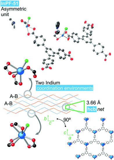 | ||
| Fig. 4 InPF-51 topology and indium coordination environment. Atom colors: Blue is indium atoms, red is oxygen atoms, green in nitrogen atoms, black is carbon atoms and white is hydrogen atoms. | ||
InPF-51 has a lower symmetry and a more stretched wave profile than InPF-50. Thus, there are two crystallographically independent indium atoms in the asymmetric unit. One of them one is heptacoordinated to three chelating btb−3 linkers and to a chloride anion. The other crystallographically independent indium cation is hexacoordinated to three carboxylate groups, two of them in a chelating way, while the third one only coordinate through one oxygen atom. A chloride ion completes the coordination sphere.
Since InPF-51 is formed by [In2(btb)2(Cl)2]2− anionic layers, protonated dimethylamine molecules that are formed from the DMF decomposition are present in the interlayer space, maintaining the charge neutrality. The uncoordinated oxygen atoms of the carboxylic groups are hydrogen bonded to the dimethyl amonium (O⋯N distance: 2.734 Å; O–H⋯N angle: 156.06°). Thermogravimetric analyses show that the loss of the amine molecules only takes place at the MOF decomposition temperature, supporting the ionic character of the interaction.
Both InPF-50 and InPF-51, due to their layered structure and its influence on the crystalline habit, present preferred orientations in powder X-ray diffraction diffractograms which are mitigated as much as possible (Fig. 5).
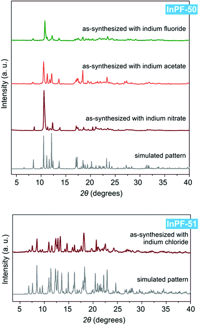 | ||
| Fig. 5 Powder X-ray diffraction patterns of InPF-50 and InPF-51 as-synthesized with the use of various indium salts, and their simulated pattern calculated from SCXRD structure. | ||
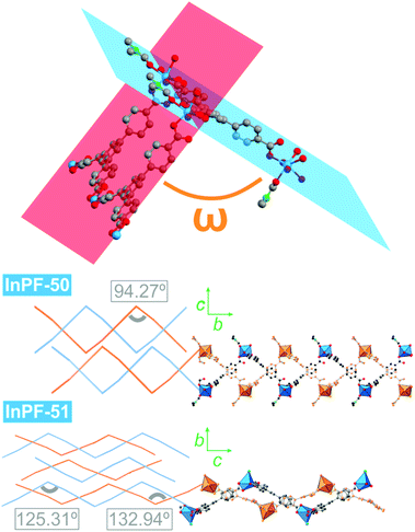
Despite both InPF-50 and InPF-51 exhibit very similar layered structures, some differences in the geometry of the layers and their packing are apparent. This can be attributed to the different charge of the layers in each MOF. Thus, (i) both catenated layers are symmetrically equivalent in InPF-50, with two pairs of them stacking along the c axis per unit cell (AA, AA disposition, Fig. 3). For InPF-51 the catenated layers are symmetrically independent one from each other, such as each one of them is formed by exclusively one of the two indium SBUs with different coordination number, as described above. Here, two pairs of catenated neutral and anionic layers stack along the b axis per unit cell (AB, AB disposition, Fig. 4). (ii) A side view of the pairs of catenated layers shows differences in their wave disposition. These are more stretched in the case of InPF-51. This is evidenced by the angle between planes (ω) defined by three indium atoms connected by a same btb3− linker. In the case of InPF-50 this angle is 94.27°, while in the case of InPF-51, two significantly larger values are found, being ω = 133.98° and ω = 125.02° (Fig. 6). (iii) In InPF-50 the space between pairs of layers is occupied by water or solvent molecules (ethanol), while in InPF-51 the catenated anionic layers alternate with protonated dimethyl amine cations to produce a neutral framework.
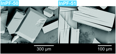
When crystals are observed by optical microscope, exfoliation planes are clearly seen. Those planes were also observed by scanning electron microscopy (SEM). They correspond to crystallographic parameter c in the case of InPF-50 and b in the case of InPF-51 (Fig. 7).
Finally, both InPF-50 and InPF-51 show thermal stability until 350 °C, according to thermal gravimetric analysis (see S3 and S4 sections of the ESI†).
Catalytic results
Due to their Lewis acidity, indium based MOFs have found application as heterogeneous catalysts in a wide range of organic transformations.29–31 Typically, indium MOFs are found to be very stable in air, as well as in water and common organic solvents.32 Recently, following with our investigation on the use of indium MOFs as heterogeneous catalysts, we have evaluated the potential use of these materials in one-pot multicomponent reactions.27,28 In particular, we have evaluated the Ugi organic transformation,33,34 which involves the condensation among four substrates, in this case a carbonyl-derivate, an amine, a carboxylic acid, and an isocyanide to form α-aminoacyl amide derivatives, which are important in the pharmaceutical industry and fine chemistry to develop organic drug-like molecule libraries.35–37 Out of the evaluated MOFs we found that those with a suitable ratio of acid and basic sites in their structure displayed the best catalytic performance.27Both, InPF-50, and -51, are formed by SBUs composed of only one metal cation, with accessible acid sites. Basic sites are also present in the form of uncoordinated carboxylic oxygen atoms. In both cases the catalytic activity is expected to take place in the external surface of the materials, as the accessible pore size is too small to allow the diffusion of the multiple substrates involved in the Ugi reaction, supported by the negligible values of accessible surface area obtained with N2 sorption measurements at 77 K. MOF crystals were subjected to a grinding and sonication process to exfoliate the materials before the catalytic tests.
We started by exploring the activity of the materials using as standard reaction the combination of benzaldehyde, aniline, benzoic acid and cyclohexyl isocyanide (Scheme 2). All the reactions were performed in an inert atmosphere of N2, under magnetic stirring. The reactants were added to the reaction in equimolar proportions except benzoic acid, which is added with a 10% excess. Yields were measured through nuclear magnetic resonance (1H NMR) (see S1 of the ESI†).
Initial tests were carried out under solvent-free conditions (Table 1 entries 1 and 4). With InPF-50 as catalyst (0.5 mol%) a yield of 54% is reached in 0.75 h, while for InPF-51 a 70% yield is obtained after 1 h. Under the same conditions, a blank experiment without use of any catalyst did not give any reaction product after 1 h reaction.
![[thin space (1/6-em)]](https://www.rsc.org/images/entities/char_2009.gif) :
:![[thin space (1/6-em)]](https://www.rsc.org/images/entities/char_2009.gif) 1
1![[thin space (1/6-em)]](https://www.rsc.org/images/entities/char_2009.gif) :
:![[thin space (1/6-em)]](https://www.rsc.org/images/entities/char_2009.gif) 1.1
1.1![[thin space (1/6-em)]](https://www.rsc.org/images/entities/char_2009.gif) :
:![[thin space (1/6-em)]](https://www.rsc.org/images/entities/char_2009.gif) 1)
1)
| Entry | Catalyst | Cat.a (mol%) | Solvent | t (h) | Yieldb (%) | TONc |
|---|---|---|---|---|---|---|
a Reaction conditions: Benzaldehyde, aniline, benzoic acid, cyclohexyl isocianide (1![[thin space (1/6-em)]](https://www.rsc.org/images/entities/char_2009.gif) : :![[thin space (1/6-em)]](https://www.rsc.org/images/entities/char_2009.gif) 1 1![[thin space (1/6-em)]](https://www.rsc.org/images/entities/char_2009.gif) : :![[thin space (1/6-em)]](https://www.rsc.org/images/entities/char_2009.gif) 1.1 1.1![[thin space (1/6-em)]](https://www.rsc.org/images/entities/char_2009.gif) : :![[thin space (1/6-em)]](https://www.rsc.org/images/entities/char_2009.gif) 1), mol% catalyst is based on the MOF crystallographic formula of InPF-51 in order to make them comparable (InPF-50: [In2(btb)2(DMF)2(H2O)2]·L; InPF-51: [In2(btb)2Cl2]2−·[NH2 (CH3)2]22+·L, N2 atmosphere, room temperature, solvent (1 mL).
b Yield by 1H NMR. Yield is calculated in relation to the excess of benzoic acid.
c TON = (mmol substrate per mmol catalyst).
d Diethylamine. 1), mol% catalyst is based on the MOF crystallographic formula of InPF-51 in order to make them comparable (InPF-50: [In2(btb)2(DMF)2(H2O)2]·L; InPF-51: [In2(btb)2Cl2]2−·[NH2 (CH3)2]22+·L, N2 atmosphere, room temperature, solvent (1 mL).
b Yield by 1H NMR. Yield is calculated in relation to the excess of benzoic acid.
c TON = (mmol substrate per mmol catalyst).
d Diethylamine.
|
||||||
| 1 | InPF-50 | 0.5 | Neat | 1 | 51 | 102 |
| 2 | InPF-50 | 0.5 | EtOH | 1 | 84 | 168 |
| 3 | InPF-50 | 1 | EtOH | 1 | 86 | 86 |
| 4 | InPF-51 | 0.5 | Neat | 1 | 70 | 140 |
| 5 | InPF-51 | 0.5 | EtOH | 1 | 85 | 170 |
| 6 | InPF-51 | 1 | EtOH | 1 | 90 | 90 |
| 7 | InPF-110 | 0.5 | Neat | 1 | 52 | 104 |
| 8 | InPF-110 | 0.5 | EtOH | 1 | 52 | 104 |
| 9 | InPF-110 | 1 | EtOH | 1 | 58 | 58 |
| 10 | — | — | Neat | 1 | Traces | — |
| 11 | Based | 1 | EtOH | 4 | 65 | 65 |
Considering that a solid product is formed, the progression of the reaction is strongly limited by the poor contact between unreacted reactants and the solid catalyst. Consequently, we decided to use ethanol as solvent to achieve better yields. As expected, with the use of ethanol as solvent, the yields increased considerably, reaching 85% with the use of InPF-51 (entry 5), and 84% in the case of InPF-50 (entry 2). A further improvement in yield was achieved by increasing the amount of catalyst to 1 mol%. With this amount of catalysts, 90% of yield for InPF-51 was reached in only one hour, and 86% for InPF-50, although at the cost of decreasing the TON. Even though both compounds have different coordination environment, in the catalytic reaction medium the labile coordinated DMF molecule in InPF-50 material drives to a 6–7 intermediate coordination number, similarly to InPF-51 with one indium hexa- and the other heptacoordinated. This fact explains the similar catalytic behavior of both compounds (Table 1).
To test whether this reaction can be catalyzed by amines, and since dimethylamine is a gas at room temperature, a test with diethylamine was carried out. Under homogeneous conditions, a 65% yield was reached after 4 h (Table 1, entry 11).
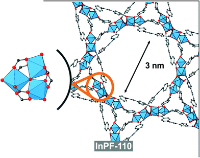
In order to compare with other indium btb3− based catalyst with absence of basic catalytic sites (no uncoordinated carboxylic oxygen atoms), we performed the same reaction with the use of InPF-110 as catalyst. InPF-110 has a mesoporous structure (pore size ca. 3 nm), and trimeric inorganic SBUs with hexacoordinated indium cations (Fig. 8). We found that the catalytic activity of InPF-110 in the Ugi reaction is lower than that of InPF-50 and -51, even though the accessible surface area of these later MOFs is merely external (Table 2 entry 9).
![[thin space (1/6-em)]](https://www.rsc.org/images/entities/char_2009.gif) :
:![[thin space (1/6-em)]](https://www.rsc.org/images/entities/char_2009.gif) 1
1![[thin space (1/6-em)]](https://www.rsc.org/images/entities/char_2009.gif) :
:![[thin space (1/6-em)]](https://www.rsc.org/images/entities/char_2009.gif) 1.1
1.1![[thin space (1/6-em)]](https://www.rsc.org/images/entities/char_2009.gif) :
:![[thin space (1/6-em)]](https://www.rsc.org/images/entities/char_2009.gif) 1)a
1)a
| Entry | Aldehyde | Amine | t (h) | Yieldb (%) | TON.c |
|---|---|---|---|---|---|
a Reaction conditions: Aldehyde, amine, benzoic acid, cyclohexyl isocianide (1![[thin space (1/6-em)]](https://www.rsc.org/images/entities/char_2009.gif) : :![[thin space (1/6-em)]](https://www.rsc.org/images/entities/char_2009.gif) 1 1![[thin space (1/6-em)]](https://www.rsc.org/images/entities/char_2009.gif) : :![[thin space (1/6-em)]](https://www.rsc.org/images/entities/char_2009.gif) 1.1 1.1![[thin space (1/6-em)]](https://www.rsc.org/images/entities/char_2009.gif) : :![[thin space (1/6-em)]](https://www.rsc.org/images/entities/char_2009.gif) 1), 1 mol% catalyst is based on InPF-51 crystallographic formula [In2(btb)2Cl2]2−·[(CH3)2NH2]22+, N2 atmosphere, room temperature.
b Yield by 1H NMR. Yield is calculated in relation to the excess of benzoic acid.
c TON = (mmol substrate per mmol catalyst). 1), 1 mol% catalyst is based on InPF-51 crystallographic formula [In2(btb)2Cl2]2−·[(CH3)2NH2]22+, N2 atmosphere, room temperature.
b Yield by 1H NMR. Yield is calculated in relation to the excess of benzoic acid.
c TON = (mmol substrate per mmol catalyst).
|
|||||
| 1 |

|

|
1 | 90 | 90 |
| 2 |

|

|
1 | 75 | 75 |
| 3 |

|

|
1 | 75 | 75 |
| 4 |

|

|
1 | 70 | 70 |
| 5 |

|

|
1.5 | 65 | 65 |
| 6 |

|

|
24 | — | — |
| 7 |

|

|
24 | — | — |
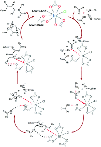
These results indicate that the catalytic activity in the Ugi reactions is not only governed by the vacant coordination sites in the indium cations, but also by the no-coordinated carboxylic oxygen atom basic centers in a dual mechanism (Fig. 9), in agreement with the previously reported.27
The scope of the reaction was performed with InPF-51 as catalyst in presence of different aldehydes and amines. The conditions in which the reactions were performed correspond to entry 6 of Table 1 (1 mol% of catalyst loading and 1 mL of ethanol at room temperature). Different aldehydes and amines were used, and the results are presented in Table 2. First, 4-fluorobenzaldehyde and 4-methylbenzaldehyde were mixed with aniline, benzoic acid and cyclohexyl isocyanide.
In both cases, yields of 75% were achieved (see entries 2 and 3). Later, in the case of the anilines, two other substrates were used, 4-methylaniline and 4-methoxyaniline. The conversion values are lower than those obtained with the aldehydes (entries 4 and 5). The methoxy group presents greater impediment and this makes the reaction more difficult to take place. Finally, we also evaluated the activity of InPF-51 with aliphatic aldehydes or amines. However, as shown in entries 6 and 7 of Table 2, no product was detected after 24 h of reaction when n-heptaldehyde or n-butylamine was employed, respectively. As reported, the catalyzed Ugi reaction would be developed through a mechanism in which a dual activation occurs (Fig. 9). This means that a number of active sites are needed in which the coordination of the indium atom is lower than 8, while at the same time the presence of Lewis basic sites is necessary. When there is an equal number of both types of active sites, the synchronization of multiple substrates activation seems to be favored, allowing the reaction to progress and obtaining high yields. Both MOFs InPF-50 and InPF-51 present carboxylate groups with non-coordinated O atoms, as well as readily removable metal-bound solvent molecules. In this dual-activation mechanism acid active sites allow the formation of the imine after activating the carbonyl group of the benzaldehyde. In parallel, the benzoic acid interacts with the basic active sites to coordinate, together and simultaneously with the imine, with the carbon of the isocyanide group. Thereafter, the reaction proceeds its course, producing a 1,4 (O–N) acyl transfer before obtaining the final product.
The recyclability of InPF-51 material was also tested in a total of 10 cycles; the catalyst was recovered after centrifugation in dichloromethane, allowing the dissolution of all products except the catalyst. The MOF maintains its crystallinity after ten catalytic cycles (S7 section of ESI†). Likewise, the catalyst can be easily reused, being readily separated from the reaction by filtration. After the tenth cycle, an 83% yield is achieved (see S7 in the ESI†). A leaching test was performed. After five minutes of reaction, the catalyst was removed by filtration, observing that after one hour only trace amounts of the final product were found. Furthermore, ICP-OES analysis of the filtrate showed that no indium atoms were dissolved.
Conclusions
Two 2D In MOFs, constructed from neutral layers (InPF-50) and anionic ones (InPF-51) have been obtained. We found that the choice of the indium salt for the MOF synthesis directs the formation of one or the other structure type. Thus, when indium chloride is employed, InPF-51 is obtained, with a structure where the layers hold an anionic charge, which is balanced by presence of protonated amines. On the other hand, use of other indium salts results in the formation of InPF-50, with a structure consisting of neutral layers.Both InPF-50 and InPF-51 show a remarkable catalytic activity as heterogeneous catalysts in the Ugi multicomponent reaction, reaching high yields (up to 90%) with the use of a small amount of catalysts (1 mol%).
By comparison of these two catalysts with other indium btb3− based catalyst with lower indium coordination number, absence of basic catalytic sites and with a mesoporous structure InPF-110, it can be inferred that the presence of Lewis basic sites in InPF-50 and -51 materials favors the synchronization in the activation of the substrates, resulting in a higher yield of the reaction. At the view of these results, it seems that the combination of inorganic SBUs composed of only one indium atom, with presence of Lewis basic sites results in highly active catalyst for the multicomponent Ugi reaction.
Conflicts of interest
There are no conflicts to declare.Acknowledgements
This work has been supported by the Spanish Ministry of Ministry of Science, Innovation and Universities Project MAT2016-78465-R, MAT2017-82288-C2-2-P, and CTQ2017-87262-R. D. R.-F. acknowledges an FPU scholarship from the Spanish Ministry of Science, Innovation and Universities. F. G. acknowledges the Spanish Ministry for Science, Innovation and Universities, for funding through the “Ramón y Cajal” program.Notes and references
- H. Furukawa, K. Cordova, M. O'Keeffe and O. Yaghi, Science, 2013, 341, 974 CrossRef CAS PubMed.
- C. Castillo-Blas and F. Gándara, Isr. J. Chem., 2018, 58, 1036 CrossRef CAS.
- W. Lu, Z. Wei, Z.-Y. Gu, T.-F. Liu, J. Park, J. Park, J. Tian, M. Zhang, Q. Zhang, T. Gentle III, M. Bosch and H.-C. Zhou, Chem. Soc. Rev., 2014, 43, 5561 RSC.
- J. Gascon, A. Corma, F. Kapteijn and F. X. Llabrés i Xamena, ACS Catal., 2014, 4(2), 361 CrossRef CAS.
- N. A. Khan, Z. Hasan and S. H. Jhung, J. Hazard. Mater., 2013, 244–245, 444 CrossRef CAS PubMed.
- D. DeSantis, J. A. Mason, B. D. James, C. Houchins, J. R. Long and M. Veenstra, Energy Fuels, 2017, 31(2), 2024 CrossRef CAS.
- Z. R. Herm, E. D. Bloch and J. R. Long, Chem. Mater., 2014, 26, 323 CrossRef CAS.
- O. Shekhah, V. Chernikova, Y. Belmabkhout and M. Eddaoudi, Crystals, 2018, 8(11), 412 CrossRef.
- H. Li, K. Wang, Y. Sun, C. T. Lollar, J. Li and H.-C. Zhou, Mater. Today, 2018, 21(2), 108 CrossRef CAS.
- R.-B. Lin, S. Xiang, H. Xing, W. Zhou and B. Chen, Coord. Chem. Rev., 2019, 378, 87 CrossRef CAS.
- A. Chidambarama and K. C. Stylianou, Inorg. Chem. Front., 2018, 5, 979 RSC.
- T. N. Nguyen, F. M. Ebrahim and K. C. Stylianou, Coord. Chem. Rev., 2018, 377, 259 CrossRef CAS.
- H. Kim, S. R. Rao, E. A. Kapustin, L. Zhao, S. Yang, O. M. Yaghi and E. N. Wang, Nat. Commun., 2018, 9, 1191 CrossRef PubMed.
- F. Fathieh, M. J. Kalmutzki, E. A. Kapustin, P. J. Waller, J. Yang and O. M. Yaghi, Sci. Adv., 2018, 4, eaat3198 CrossRef PubMed.
- U. Mueller, M. Schubert, F. Teich, H. Puetter, K. Schierle-Arndt and J. Pastré, J. Mater. Chem., 2006, 16, 626 RSC.
- N. C. Burtch, H. Jasuja and K. S. Walton, Chem. Rev., 2014, 114(20), 10575 CrossRef CAS PubMed.
- X. Zhao, C. Mao, X. Bu and P. Feng, Chem. Mater., 2014, 26(8), 2492 CrossRef CAS.
- P. Horcajada, R. Gref, T. Baati, P. K. Allan, G. Maurin, P. Couvreur, G. Férey, R. E. Morris and C. Serre, Chem. Rev., 2012, 112(2), 1232 CrossRef CAS PubMed.
- K. B. Sezginel, P. A. Asinger, H. Babaei and C. E. Wilmer, Chem. Mater., 2018, 30(7), 2281 CrossRef CAS.
- A. Corma, H. Garcia and F. X. Llabres i Xamena, Chem. Rev., 2010, 110(8), 4606 CrossRef CAS PubMed.
- L. M. Aguirre-Díaz, D. Reinares-Fisac, M. Iglesias, E. Gutiérrez-Puebla, F. Gándara, N. Snejko and M. A. Monge, Coord. Chem. Rev., 2017, 335, 1 CrossRef.
- M. H. Alkordi, Y. Liu, R. W. Larsen, J. F. Eubank and M. Eddaoudi, J. Am. Chem. Soc., 2008, 130, 12639 CrossRef CAS PubMed.
- J. A. Johnson, J. Luo, X. Zhang, Y.-S. Chen, M. D. Morton, E. Echeverría, F. E. Torres and J. Zhang, ACS Catal., 2015, 5, 5283 CrossRef CAS.
- Y.-H. Li, S.-L. Wang, Y.-C. Su, B.-T. Ko, C.-Y. Tsaib and C.-H. Lin, Dalton Trans., 2018, 47, 9474 RSC.
- L. M. Aguirre-Díaz, F. Gándara, M. Iglesias, N. Snejko, E. Gutiérrez-Puebla and M. A. Monge, J. Am. Chem. Soc., 2015, 137(19), 6132 CrossRef PubMed.
- A. L. M. Aguirre-Díaz, M. Iglesias, N. Snejko, E. Gutiérrez-Puebla and M. A. Monge, RSC Adv., 2015, 5, 7058 RSC.
- L. M. Aguirre-Díaz, M. Iglesias, N. Snejko, E. Gutiérrez-Puebla and M. A. Monge, Chem. – Eur. J., 2016, 22, 6654 CrossRef PubMed.
- D. Reinares-Fisac, L. M. Aguirre-Díaz, M. Iglesias, N. Snejko, E. Gutiérrez-Puebla, M. A. Monge and F. Gándara, J. Am. Chem. Soc., 2016, 138(29), 9089 CrossRef CAS PubMed.
- H. N. K. Lam, N. B. Nguyen, G. H. Dang, T. Truong and N. T. S. Phan, Catal. Lett., 2016, 146, 2087 CrossRef CAS.
- R. Babu, R. Roshan, Y. Gim, Y. H. Jang, J. F. Kurisingal, D. W. Kim and D.-W. Park, J. Mater. Chem. A, 2017, 5, 15961 RSC.
- P. T. K. Nguyen, H. T. D. Nguyen, H. N. Nguyen, C. A. Trickett, Q. T. Ton, E. Gutiérrez-Puebla, M. A. Monge, K. E. Cordova and F. Gándara, ACS Appl. Mater. Interfaces, 2018, 10(1), 733 CrossRef CAS PubMed.
- S. Yuan, L. Feng, K. Wang, J. Pang, M. Bosch, C. Lollar, Y. Sun, J. Qin, X. Yang, P. Zhang, Q. Wang, L. Zou, Y. Zhang, L. Zhang, Y. Fang, J. Li and H.-C. Zhou, Adv. Mater., 2018, 30, 1704303 CrossRef PubMed.
- I. Ugi, Angew. Chem., Int. Ed. Engl., 1962, 1, 8 CrossRef.
- A. Dömling and I. Ugi, Angew. Chem., Int. Ed., 2000, 39, 3168 CrossRef.
- M. Krasavin, V. Parchinsky, A. Shumsky, I. Konstantinov and A. Vantskul, Tetrahedron Lett., 2010, 51, 1367 CrossRef CAS.
- L. Moni, F. De Moliner, S. Garbarino, J. Saupe, C. Mang and A. Basso, Front. Chem., 2018, 6, 369 CrossRef PubMed.
- T. Newhouse, P. S. Baran and R. W. Hoffmann, Chem. Soc. Rev., 2009, 38(11), 3010 RSC.
Footnote |
| † Electronic supplementary information (ESI) available: Experimental procedure, characterization, SCXRD crystal data, structure refinement and CIF files); catalytic experimental procedure and background; catalytic activity data and product characterization (PDF file). CCDC 1483221 and 1873905. For ESI and crystallographic data in CIF or other electronic format see DOI: 10.1039/c8dt04977g |
| This journal is © The Royal Society of Chemistry 2019 |


