Ceria–zirconia encapsulated Ni nanoparticles for CO2 methanation†
Received
18th July 2019
, Accepted 11th August 2019
First published on 12th August 2019
Abstract
We prepared uniformly-sized Ni nanoparticles on ceria–zirconia (CZ) as model catalysts for CO2 methanation in the context of renewable energy storage. CZ was synthesized via a sol–gel method with Ni being introduced either via incipient-wetness impregnation on calcined CZ or as a colloidal Ni nanoparticle (NiNP) dispersion during sol–gel synthesis. Catalysts were characterized with XRD, N2 physisorption, H2-TPR, H2 chemisorption, XPS and HAADF-STEM with EDX mapping. The Ni/CZ (IWI) catalyst contained large Ni particles after reduction, whereas co-gelation led to NiNP encapsulated in CZ, the particles retaining their initial size of 4.5 nm obtained by the earlier colloidal synthesis. Encapsulated Ni@CZ exhibited superior catalytic activity and stability for CO2 methanation over Ni/CZ. A comparison of Ni@CZ with (encapsulated) Ni@SiO2 prepared from the same colloidal NiNP dispersion showed that CZ shows a strong synergy with Ni in CO2 methanation and results in an order of magnitude higher activity compared to SiO2.
1. Introduction
The impact of climate change and the search for renewable energy sources that can lower our carbon emissions has led to a resurgence of research into carbon dioxide (CO2) valorization over the last decade.1–4 In particular, interest in the Sabatier reaction has been the focus of several recent works and reviews, in which conversion of CO2 to methane (CH4) is regarded as a viable technology to store hydrogen (H2).5–8 To ensure the overall sustainability of this process, it is vital that the H2 is produced via efficient water electrolysis that is powered by renewable energy.9,10 Besides the higher energy density of CH4 compared to H2, such a Power-to-Gas strategy has the benefit that CH4 can be directly used in the existing natural gas infrastructure.11 In CO methanation, which is used at a practical scale for instance in steam methane reforming to produce pure H2 streams, Ni-based catalysts dispersed on oxidic supports are preferred due to their high activity and CH4 selectivity, and their considerably lower price than precious group metal ones.11,12 With respect to CO2 methanation (Sabatier reaction), Ni catalysts supported on Al2O3,13–15 SiO2,16,17 and TiO2,18 have all been investigated, and support effects have been shown to significantly influence the activity and stability of Ni-based methanation catalysts.19–21
In recent years, also CeO2 (ref. 22–29) and ZrO2 (ref. 29–33) supported Ni catalysts have been shown to be promising for CO2 methanation in comparison to conventional supports such as SiO2 or Al3O3. Reducible supports such as CeO2 and ceria–zirconia (CZ) are particularly advantageous due to their redox properties originating from Ce existing with oxidation states Ce3+ and Ce4+.34 These supports can generate oxygen vacancies during catalyst reduction which can facilitate CO2 activation.35 So far, only a few studies have dealt with CZ-supported Ni catalysts. Ocampo et al. were the first to study the catalytic activity and stability of ceria–zirconia supported Ni for CO2 methanation.36 Employing a sol–gel-type approach for catalyst preparation, the authors investigated the influence of Ni content (5–15 wt%) supported on Ce0.72Zr0.28O2 on the properties and catalytic behavior in the Sabatier reaction. All catalysts lost some activity over time, and lower loaded Ni catalysts deactivated the most over a 150 h stability test. Later studies sought to optimize Ce/Zr ratios and found that the highest methanation activity and stability was obtained for Ni catalysts dispersed on supports with Ce/Zr ratios close to unity.37 In addition, Aldana et al. compared the methanation activity of such sol–gel derived catalysts with impregnated Ni–CZ catalysts, emphasizing the advantage of the former preparation method with respect to activity and stability.38 Pan et al. also studied Ni–CZ catalysts with the aim to develop a mechanistic understanding of CO2 methanation,39 a subject that is still under intense debate and which is strongly dependent on the nature of the support.40,41 Elsewhere, Ni/CZ and other CZ-supported base-metal catalysts have been studied in plasma-assisted CO2 methanation catalysis.42–45
Numerous synthetic procedures have been described in the literature to synthesize CZ-supported Ni catalysts for methanation reactions. The work by Ocampo et al. compared impregnation and sol–gel methods to obtain CZ-supported Ni particles sized between 10 and 30 nm. Sintering of the metallic Ni particles under CO2 methanation conditions led to a significant loss in catalytic activity.36,37,46 Ashok et al. prepared Ni/Ce0.5Zr0.5O2 catalysts via impregnation, deposition–precipitation (DP), and ammonia evaporation and compared their activity in CO2 methanation. Catalysts prepared via ammonia evaporation were the most active and showed the highest selectivity towards methane.47 Interestingly, these findings contrast an earlier study by Pan et al., who found that impregnation led to better CO2 methanation catalysts than either DP or urea combustion.48 To the best of our knowledge, none of the recent works in which CZ was the support could accurately control the Ni particle size, and for all of these studies notable catalyst deactivation during CO2 methanation stability tests was reported. A direct side-by-side comparison of such systems is lacking.
While colloidal synthesis routes have long been proposed as a promising strategy to synthesize well-defined catalysts, to date, colloidal routes towards CZ-supported Ni catalysts have not yet been explored. Our recent work reported that colloidal Ni nanoparticles (NiNPs) can be synthesized with sizes in the 3–8 nm range by employing a seed-mediated approach.49 An effective strategy to support such NiNPs and obtain active hydrogenation catalysts was to encapsulate them in a silica (SiO2) support grown around the NiNPs. Work by Pu et al. highlighted the possibility of encapsulating Ni particles in supports other than SiO2 including Al2O3, TiO2 and CeO2, although the final particle sizes were significantly larger than those of conventional Ni-based hydrogenation catalysts.50 Encouraged by the superior activity, stability, and sinter-resistance of encapsulated NiNPs, it is worthwhile to extend this approach to other supports like CZ to produce more efficient Ni-based catalysts.
In this work, we report the preparation of well-defined CZ-supported NiNPs prepared via a colloidal approach combined with a co-gelation procedure. Ceria–zirconia synthesized by sol–gel methods was employed to obtain a homogeneous solid-solution of Ce0.5Zr0.5O2. By introducing a colloidal dispersion of NiNPs with a narrow particle size distribution into the sol prior to gelation and aging, NiNPs were homogeneously dispersed in the final CZ solid solution and maintained their original particle size. The catalytic activity and stability of the resulting Ni@CZ in CO2 methanation were superior in comparison to a Ni/CZ catalyst synthesized via incipient-wetness impregnation (IWI). A comparison is made between NiNPs of the same size encapsulated in CZ and SiO2 (see ref. 49). Our approach demonstrates that CZ-supported Ni catalysts may be tailored to obtain catalysts with a desired particle size distribution.
2. Experimental
2.1 Materials
Nickel acetylacetonate (anhydrous, 95%) was purchased from Strem, and nickel nitrate hexahydrate (99.999%), cerium(III) nitrate hexahydrate (99.99%), zirconyl chloride octahydrate (99.99%), oleylamine (OAm, technical, >70%), oleic acid (OAc, 90%), borane tert-butylamine complex (BTB, 97%), poly(ethylene glycol) (Pluronic P123, Mn = 5800, EO20PO70EO20), from Sigma Aldrich. Toluene (99.7%), and CHCl3 (99.9%) were purchased from Biosolve. All chemicals were used as received without further purification.
2.2 Synthesis methods
2.2.1 Colloidal nanoparticle synthesis.
Colloidal Ni nanoparticles were prepared using methods derived from literature,51–53 as described in our previous work.49 To summarize, a 250 mL two-neck round-bottomed flask with a magnetic stirring bar was loaded with 257 mg Ni(acac)2 (1 mmol), 15 mL oleylamine (OAm) and 0.32 mL oleic acid (OAc, 1 mmol) and brought under inert conditions in Ar. To remove oxygen and water, the mixture was heated to 110 °C under Ar and rigorous stirring, and degassed for 30 min to yield a green-blue solution. The Ni(acac)2 solution was subsequently cooled to 90 °C. In a second flask, 0.44 g borane tert-butyl amine complex (BTB, 5 mmol) was dissolved in 2 mL OAm and brought under inert conditions in Ar. The BTB solution was degassed under rigorous stirring. Next, the BTB solution was rapidly injected into the Ni(acac)2 solution. The mixture turned black within 30 s, indicating the reduction of the Ni2+ to Ni0. The mixture was kept at 90 °C for 1 h, after which the synthesis was quenched by adding 17 mL toluene and removing the heat source to cool the mixture to room temperature. The colloidal dispersion was divided across six centrifuge tubes, and the nanoparticles were precipitated by adding ca. 45 mL acetone as an anti-solvent, followed by centrifugation (5000 rpm, 10 min). The supernatant was decanted and the particles were washed to remove excess organic ligands by redispersing them in 5 mL toluene and precipitating them with 45 mL acetone and centrifugation. Particles were thoroughly washed 3 times with the toluene/acetone mixture.
2.2.2 Sol–gel synthesis of CeZrO4.
A method adapted from Yuan et al. was followed to synthesize CeZrO4 (CZ) using a sol–gel approach.54 To obtain the sol, 0.8 g of Pluronic P123, 1.736 g Ce(NO3)3·6H2O (4.00 mmol), and 1.288 g ZrOCl2·8H2O (4.00 mmol) were dissolved in 16 mL ethanol. The sol was stirred at room temperature for 2 h for homogenization. Next, the sol was transferred to an oven at 40 °C with a relative humidity of 50%, achieved by placing a petri-dish of deionized water in the oven. The sol–gel was aged for 48 h, after which the gel was dried at 100 °C for 24 h. The dried material was calcined in air by heating to 500 °C at a rate of 1 °C min−1 followed by an isothermal dwell for 4 h.
2.3 Catalyst synthesis
Ni/CZ (incipient-wetness impregnation, IWI).
A catalyst with intended Ni loading of 2 wt% was prepared by incipient-wetness impregnation of a CZ support synthesized by the sol–gel procedure described earlier. A requisite amount of Ni(NO3)2·6H2O salt was dissolved in 0.4 mL deionized water and added dropwise to 1 g of the CZ. The resulting solid was then dried overnight at 110 °C and calcined in air at 500 °C by heating at a rate of 1 °C min−1 followed by an isothermal dwell of 4 h.
Encapsulation of NiNPs in CZ.
A sol was prepared identical to the approach outlined above. To obtain the sol, 0.8 g of Pluronic P123, 1.736 g Ce(NO3)3·6H2O (4.00 mmol), and 1.288 g ZrOCl2·8H2O (4.00 mmol) were dissolved in 16 mL ethanol. The sol was stirred at room temperature for 2 h to yield a homogeneous sol. Next, the sol was transferred to an oven at 40 °C with a relative humidity of 50% and kept for 2 h. In the meantime, colloidal NiNPs (ca. 100 mg) were dispersed in 5 mL CHCl3 at room temperature. After 2 h, the NiNP dispersion was added to the sol–gel and stirred for 10 min at room temperature to obtain a homogeneous black mixture. The NiNP-containing sol–gel was returned to the oven at 40 °C aged for 48 h. The resulting gel was transparent, which indicated that the NiNPs were well-dispersed throughout the gel. Next, the gel was dried at 100 °C for 24 h, and calcined in air at 500 °C achieved by heating the material at a rate of 1 °C min−1 followed by an isothermal dwell of 4 h. CZ-encapsulated NiNPs are denoted as Ni@CZ.
2.4 Characterization
Elemental analysis.
The Ni content of the prepared samples was determined by ICP-OES using a Spectro Blue ICP apparatus. A stock acid solution was prepared by dissolving 20 g ammonium sulfate in 30 mL concentrated sulfuric acid (95–98%). Samples (25 mg) were dissolved in 5 mL of the stock acid solution at 250 °C.
X-ray diffraction.
The phase purity, crystallinity, and average particle size of the CZ support and Ni–CZ catalysts were investigated by XRD. Samples were finely ground and pressed into sample holders prior to measurements. Diffractograms were recorded on a Bruker D2 Phaser diffractometer using Cu Kα radiation with a wavelength of 1.54 Å. The 2θ angles between 20–80° were measured with a step size of 0.02° at 1.0 s per step. For encapsulated Ni@CZ, an additional small angle measurement was performed between 0.1–1°, with a step size of 0.0015° at 0.25 s per step.
N2 physisorption.
Textural properties of the CZ support and Ni–CZ catalysts were performed at −196 °C on a Micromeritics TriStar II 3020. The samples (ca. 150 mg) were degassed at 120 °C for at least 12 h prior to N2 physisorption measurements. Surface areas were calculated using the Brunauer–Emmett–Teller (BET) method, and total pore volumes and pore size distributions were computed by the Barrett–Joyner–Halenda (BJH) method using the desorption branch of the isotherm.
Temperature programmed reduction (H2-TPR).
The reducibility of the CZ support and Ni–CZ catalysts was studied with H2-TPR in a Micromeritics AutoChem II. In a typical measurement, 100 mg of sample was loaded in a quartz U-tube reactor with quartz wool before and after the catalyst bed. Prior to H2-TPR measurements, samples were heated to 130 °C under He flow for 1 h to remove adsorbed water. TPR was performed by linearly heating the sample from 50 °C to 1000 °C in a flow of 4 vol% H2 in He (50 mL min−1). The H2 consumption was measured by a TCD and calibrated against a CuO/SiO2 reference catalyst.
H2 chemisorption.
The available active sites for Ni–CZ catalysts were investigated by H2 chemisorption using a Micromeritics ASAP 2020. In a typical measurement, a quartz U-tube reactor was loaded with100 mg catalyst, with quartz wool before and after the catalyst bed. The catalysts were reduced in situ at 500 °C by heating to this temperature at a rate of 5 °C min−1, followed by an isothermal dwell of 4 h. The catalysts were evacuation at 520 °C for 3 h to remove all hydrogen species, and H2 chemisorption was performed at 120 °C.
Transmission electron microscopy (TEM).
Particle sizes of colloidal nanoparticles was determined with TEM. Bright-field TEM measurements were performed on a FEI Tecnai 20 (type Sphera) transmission electron microscope operating at 200 kV. Approximately 100 mg of the NiNPs was finely crushed and ultrasonically suspended in pure CHCl3, and dispersed over a Cu grid with a holey carbon film.
STEM-EDX.
The average Ni particle size, the particle size distribution and the distribution of Ce and Zr in the samples was studied using scanning transmission electron microscopy-energy-dispersive X-ray spectroscopy (STEM-EDX). Measurements were carried out on a FEI cubed Cs-corrected Titan operating at 300 kV. Ni–CZ samples were crushed, sonicated in ethanol and dispersed on a holey Cu support grid. Elemental analysis was done with an Oxford Instruments EDX detector X-MaxN 100TLE.
X-ray photoelectron spectroscopy (XPS).
Depth profiling was employed to compare the surface Ni/support ratios in Ni/CZ and encapsulated Ni@CZ catalysts. The catalysts were reduced ex situ at 500 °C and passivated in 1 vol% O2 in He (6 h). Finely crushed samples were placed on double-sided carbon tape and were studied after exposure to an Ar+ ion gun at 3.0 keV for 0–300 s. Ni/(Ce + Zr) area ratios were used to estimate the elemental composition. Spectra were obtained using a K-Alpha XPS apparatus (Thermo Scientific) equipped with an Al anode (Al Kα = 1486.68 eV). To accommodate for the low Ni content and achieve sufficient signal/noise ratios, 50 scans were measured and averaged in the Ni 2p, and 20 scans in both the Ce 3d and Zr 3d regions. All spectra were analyzed using the CasaXPS software package and charge corrected against the C 1s binding energy of adventitious carbon at 284.8 eV. Surface element loadings were obtained by integrating the areas of the Ni 2p3/2, Ce 3d and Zr 3d regions using a Shirley background.
2.5 Catalytic activity
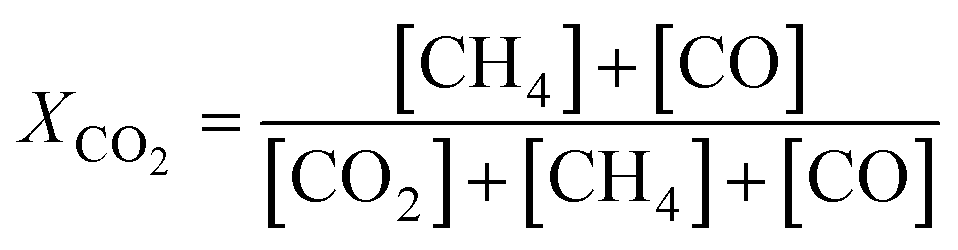
The catalytic activity of the prepared samples in CO2 methanation was studied at 1 atm in a 10-channel high-throughput flow reactor setup. CZ-supported samples were pelletized at a pressure of 300 MPa and sieved to a 75–125 μm fraction. Each quartz reactor tube (internal diameter 0.4 cm) was loaded with a homogeneous mixture of 50 mg catalyst (75–125 μm) diluted with 150 mg SiC to improve heat and mass transfer. Quartz wool was used before and after the catalyst bed. Prior to catalytic testing the samples were reduced in situ at 500 °C for 4 h in 10 vol% H2 in He (50 mL min−1). The catalytic activity was tested with a supply of 3 vol% CO2, 12 vol% H2, and 85 vol% He (50 mL min−1). The reaction products were analyzed by online gas chromatography (Interscience CompactGC) equipped with Restek Rt-Q-Bond and Rt-Msieve 5 Å (TCD), Restek Rt-U-Bond and Rt-Q-Bond (TCD), and Restek Rtx-1 (FID) columns. CH4, CO, and H2O were the only observed reaction products. Steady-state CO2 conversion was measured between 200–400 °C. The stability of the catalyst is tested at 350 °C for 60 h with the same gas feed composition. The CO2 conversion (XCO2), and CH4 (SCH4) and CO (SCO) selectivities are calculated as:| |  | (1) |
| |  | (2) |
| |  | (3) |
3. Results and discussion
3.1 Catalyst synthesis and characterization
A schematic of the co-gelation procedure to obtain Ni@CZ is given in Fig. 1. Colloidal NiNPs were obtained from a Ni2+-containing solution at 90 °C using BTB as external reducing agent. TEM showed that this procedure yielded NiNPs with an average size of 4.4 nm and a narrow particle size distribution (Fig. 2). XRD patterns did not contain peaks due to crystalline Ni or NiO phases (ESI†).55,56
 |
| | Fig. 1 Schematic illustration of NiNP synthesis and encapsulation in CZ. | |
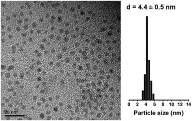 |
| | Fig. 2 TEM image and particle size distribution of unsupported colloidal NiNPs. | |
Next, supported Ni catalysts were synthesized by either incipient-wetness impregnation on calcined CZ support or by co-gelation of a NiNP dispersion with CZ precursors, denoted as Ni/CZ and Ni(x)@CZ respectively, where x represents the colloidal NiNP particle size prior to encapsulation. Table 1 summarizes the physical properties of supported materials. In both cases, sol–gel approaches were followed to obtain the CZ mixed oxides, with the final catalysts containing ∼2 wt% Ni. The encapsulated Ni(4.4)@SiO2 catalyst was characterized and discussed in more detail in earlier work (see ref. 49).
Table 1 Physico-chemical properties of prepared materials
| Sample |
Ni wt% |
SA (m2 g−1)a |
V
tot (cm3 g−1) |
d
pore (nm) |
d
CZ (XRD, nm) |
d
Ni (TEM, nm) |
|
Surface area determined by BET method.
See previous work ref. 49.
Determined by small-angle XRD.
|
| CeZrO4 |
0 |
74 |
0.087 |
3.5 |
6.8 |
n/a |
| Ni/CZ |
1.8 |
70 |
0.094 |
4.0 |
7.0 |
>20 |
| Ni(4.4)@CZ |
1.9 |
80 |
0.099 |
3.5 |
5.7 |
4.5 (±0.8) |
| Ni(4.4)@SiO2b |
2.4 |
979 |
1.46 |
4.4c |
n/a |
4.3 (±0.6) |
The XRD patterns of the calcined catalysts and CZ support are shown in Fig. 3. No reflections from NiO were observed neither for Ni/CZ or Ni@CZ, although this could also be due to the low Ni content. Peaks at 29.2°, 33.8°, 48.7°, and 57.7° correspond to the (101), (002), (112), and (103) planes of CeO2–ZrO2 fluorite-phase solid solutions (JCPDS no. 74-8060). No reflections were observed for bulk CeO2 or ZrO2, and no other CZ phase reflections were found even after high-temperature calcination (ESI†).57 Crystallite size was determined using the Scherrer equation and the FWHM of the (101) reflection. Interestingly, by introducing NiNPs during the sol–gel synthesis procedure, smaller (5.7 nm) CZ crystallites were obtained compared to CZ-only (6.8 nm) (Table 1). This slight decrease in CZ crystallite size can be an effect of including additional surfactant (originating for the colloidal NiNP dispersion) into the sol–gel solution, which may subsequently influence the aging step to provide smaller CZ particles.
 |
| | Fig. 3 XRD patterns of CZ samples prepared via sol–gel methods. | |
The specific surface areas of CZ materials determined by N2 physisorption isotherms (ESI†) were of the same order and ranged between 70–80 m2 g−1. All isotherms can be categorized as type IV with an H2-shaped hysteresis loop, which points to mesopores.54 Encapsulated Ni(4.4)@CZ has the largest pore volume (Table 1). Average pore sizes, obtained by applying the Barrett–Joyner–Halenda (BJH) method to the desorption branch of the isotherm, were between 3.5–4.0 nm with a narrow distribution for both CZ materials (ESI†). However, small-angle XRD did not show a clear peak for the (100) reflection, which suggests that the hysteresis loop originates from the voids between aggregated CZ crystallites, with the smaller crystallites yielding the largest pore volume.
The reducibility of the synthesized materials was studied by H2-TPR. Fig. 4 shows the weight-normalized reduction profiles between 50–1000 °C with the corresponding hydrogen consumption and estimated Ce reduction degree shown in Table 2. Ni-free CZ exhibits a single reduction maximum around 580 °C, which is attributed to the reduction of Ce4+ to Ce3+.36 TPR profiles of Ni/CZ and Ni(4.4)@CZ show a clear shift in the reduction peak to lower temperature, indicating that Ce4+ reducibility is enhanced by Ni. The general TPR profiles of both Ni catalysts are similar. A sharp peak around 350 °C is attributed to the reduction of bulk NiO. In addition, a second peak around 400 °C is attributed to the reduction of Ni2+ with a stronger Ni-support interaction. The Ni reduction features envelop the Ce4+ reduction profile. Interestingly, the excess consumed H2 (i.e. the difference between the total H2 consumed and H2 required to fully reduce Ni2+) decreased for Ni(4.4)@CZ compared with the impregnated catalyst. This might be explained by increased hydrogen spillover on the impregnated Ni/CZ catalyst compared to Ni(4.4)@CZ. From weight-normalized H2 chemisorption measurements (Table 2), we observe that the impregnated catalyst chemisorbs a larger amount of H2, despite having a lower Ni content and larger average particle size after reduction. This confirms that there is likely more H2 spillover on the impregnated catalyst which leads to a higher excess H2 consumed as determined from the TPR data.
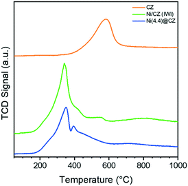 |
| | Fig. 4 Weight-normalized H2-TPR profiles of sol–gel prepared CZ and Ni-containing catalysts. | |
Table 2 Catalyst reducibility and available active sites determined by H2-TPR and total H2 chemisorption
| Sample |
H2-TPR (mmol g−1) |
Excess H2 consumeda (mmol g−1) |
H2 chemisorption (mmol g−1) |
|
Estimated from the difference between total H2 consumption and H2 required to fully reduce Ni2+ during H2-TPR.
See previous work ref. 49.
|
| CZ |
0.75 |
n/a |
n.m. |
| Ni/CZ |
1.21 |
0.91 |
0.037 |
| Ni(4.4)@CZ |
0.98 |
0.66 |
0.033 |
| Ni(4.4)@SiO2b |
0.40 |
0 |
0.019 |
To verify whether Ni was encapsulated in CZ after reduction at 500 °C in 10 vol% H2 in He, materials were studied with XPS depth-profiling. Fig. 5 shows the surface Ni/(Ce + Zr) ratio (corrected for the relative sensitivity of each element) after exposure to Ar sputtering between 0–300 s. The Ni/(Ce + Zr) ratios were substantially different between Ni/CZ and Ni(4.4)@CZ samples. The sputtering profile of the impregnated Ni/CZ sample showed a significant decrease in the Ni/(Ce + Zr) ratio with every Ar etching dose. This is a clear indication that the Ni particles are present on the outer surface of the CZ support. In contrast, Ni(4.4)@CZ prepared by NiNP encapsulation has a much lower Ni/(Ce + Zr) XPS ratio before Ar sputtering. After Ar+ etching of 300 s, the metal-to-support ratio increased, confirming an increase in the Ni content below the support surface. Similar trends were observed in our works on SiO2 encapsulated NiNPs.49
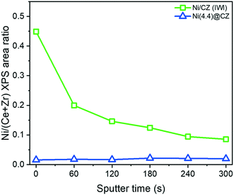 |
| | Fig. 5 Depth profile of impregnated Ni/CZ and encapsulated Ni(4.4)@CZ derived from Ni/(Ce + Zr) surface ratios measured by XPS. Catalysts were exposed to 5 iterations of Ar+ sputtering (60 s each) to obtain a depth profile. | |
3.2 The effect of encapsulation on particle size
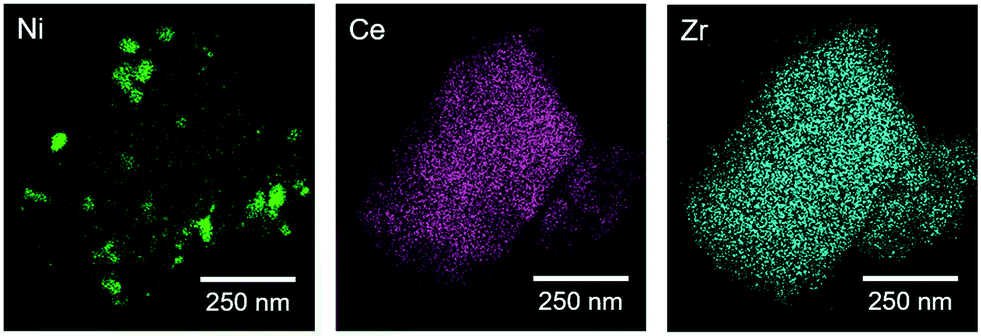
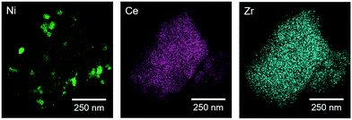
Due to the low contrast between Ni and CZ in bright field TEM, particle sizes in Ni/CZ and Ni(4.4)@CZ catalysts after reduction at 500 °C (4 h, 5 °C min−1) were determined with HAADF-STEM with EDX mapping. Fig. 6 shows the elemental maps of Ni, Ce, and Zr in Ni/CZ. The Ce and Zr maps show a homogeneous mixture of Ce and Zr, confirming the presence of CeZrO4 as a solid solution. Compared with the crystallite sizes determined by XRD, the HAADF-STEM measurements show CZ crystallites that are considerably larger than ca. 6 nm. This discrepancy is because the large CZ crystals are composed of agglomerates of the smaller CZ crystallites (ESI†). The Ni map shows significant Ni aggregation occurred during the reduction pretreatment step. Ni aggregates up to around 150–200 nm were observed, indicating significant Ni sintering occurred during reduction. Fig. 7 shows the corresponding EDX maps for encapsulated Ni(4.4)@CZ. Similar to the impregnated sample, the Ce and Zr elemental maps confirm that CZ is a solid solution. In contrast, Ni particles retained their colloidal NiNP size, with encapsulated nanoparticles showing an average diameter of 4.5 nm with a narrow particle size distribution. As described earlier, the quantity of H2 chemisorbed by impregnated and encapsulated catalysts was almost identical (Table 2), indicating that there was significantly more hydrogen spillover on the impregnated Ni/CZ than on Ni(4.4)@CZ. These findings are surprising, as we would expect the smaller particles to have a stronger metal–support interaction, and therefore to lead to more significant H2 spillover. However, the lower amount of hydrogen spillover may also be an indicator that the encapsulated Ni phase is not fully accessible, resulting in decreased spillover for encapsulated catalysts. Loss of Ni accessibility was also observed in SiO2-encapsulated NiNPs,49 and would need to be verified by other spectroscopic methods for CZ-supported catalysts in a more detailed study.
 |
| | Fig. 6 STEM-EDX images showing the elemental maps of Ni, Ce, and Zr for Ni/CZ after reduction at 500 °C. | |
 |
| | Fig. 7 STEM-EDX images showing the elemental maps of Ni, Ce, and Zr for Ni(4.4)@CZ after reduction at 500 °C. | |
3.3 Catalytic performance in CO2 methanation: the effect of encapsulation and support effects
The CO2 methanation activities of Ni/CZ, Ni(4.4)@CZ, and Ni(4.4)@SiO2 were at atmospheric pressure. CZ-supported catalysts were reduced in situ at 500 °C in 10 vol%. H2 in He, while Ni(4.4)@SiO2 was reduced at 600 °C, prior to introducing the methanation gas composition at 200 °C. A stoichiometric H2/CO2 ratio of 4 was used. Fig. 8a shows the catalytic activity in CO2 methanation and corresponding CO selectivity (Fig. 8b) between 200–400 °C. The catalytic activity (Fig. 8c) and CO selectivity (Fig. 8d) were followed was for 60 h under these conditions.
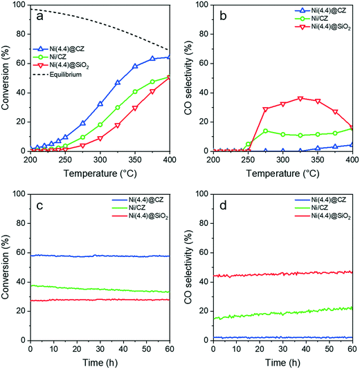 |
| | Fig. 8 CO2 methanation (H2/CO2 = 4, 50 mL min−1) activity for impregnated and encapsulated CZ-supported catalysts showing (a) CO2 conversion and (b) CO selectivity between 200–400 °C. (c) CO2 conversion and (d) CO selectivity were followed for 60 h at 350 °C to study the catalyst aging and stability. For comparison, a Ni(4.4)@SiO2 catalyst was also employed (see ref. 49). | |
Both CZ-supported catalysts were active towards CO2 methanation between 200–400 °C and showed a typical Arrhenius behavior below 250 °C. Higher CO2 conversion was observed for encapsulated Ni(4.4)@CZ in comparison to Ni/CZ. In addition, NiNP encapsulation in CZ led to a lower CO selectivity as well. Reaction rates normalized to total Ni content were determined at conversions below 10% to ensure differential conditions in the reactor. Kinetic results are summarized in Table 3. Thus, CH4 production rates for encapsulated Ni(4.4)@CZ were more than two times higher than for impregnated Ni/CZ. Similar trends were also observed from the turnover frequencies (TOFs) determined from H2 chemisorption data (ESI). However, the excess H2 chemisorbed on CZ supported catalysts meant that it was not possible to compare catalytic activities normalized to available active sites. Nevertheless, the improved activity is also reflected in the apparent activation energy for the encapsulated NiNPs. Importantly, the apparent activation energy (calculated with respect to CH4 formation) of Ni(4.4)@CZ (68 kJ mol−1) is in line with literature values for CO2 methanation on Ni-based systems, thereby demonstrating that these catalysts are not affected by diffusion limitations.58 A support effect can be noted by comparing the catalytic activity of the two catalysts prepared via NiNP encapsulation in CZ and SiO2, respectively. Rates over Ni(4.4)@CZ were almost an order of magnitude higher than those calculated for Ni(4.4)@SiO2, highlighting a significant increase in activity attributable to the CZ support.
Table 3 Kinetic results for supported catalysts for CO2 methanation at 250 °C
| Catalyst |
Conversion (%) |
CH4 selectivity (%) |
Rates (10−3 mol CH4 per mol Ni per s) |
E
appact (kJ mol−1) |
|
See previous work ref. 49.
|
| Ni/CZ |
3.7 |
95 |
2.35 (±0.02) |
81 |
| Ni(4.4)@CZ |
9.5 |
100 |
6.15 (±0.04) |
68 |
| Ni(4.4)@SiO2a |
1.3 |
100 |
0.64 (±0.03) |
75 |
Similar trends were observed during the 60 h stability test at 350 °C. All catalysts showed CO2 conversions below the thermodynamic equilibrium (79%). Fig. 8c shows that Ni(4.4)@CZ maintained 58% conversion throughout the stability study. In contrast, impregnated Ni/CZ had a lower initial activity (37%) and gradually deactivated, reaching 33% conversion after 60 h. Encapsulation also suppressed the formation of CO, with Ni(4.4)@CZ maintaining CO selectivity below 2.5%. On the contrary, Ni/CZ saw a gradual increase in the CO selectivity from 15% to 23%. Notably, both catalysts prepared by encapsulation maintained their activity during the stability test at 350 °C. In line with the initial temperature programmed reaction data, the CO selectivity of Ni@SiO2 remained between 43–47%, which is considerably higher than that of Ni@CZ.
An important advantage of using colloidal synthetic approaches to prepare well-defined catalysts is that support effects can be probed directly, with catalysts being prepared using the exact same batch of colloidal NiNPs. The Ni(4.4)@CZ and Ni(4.4)@SiO2 catalysts were prepared using the exact same colloidal NiNPs, differing only in the nature of the support. For both materials, the NiNPs maintained their original particle size. We can make a direct assessment of the support effects from the CZ and SiO2 encapsulated NiNPs, because the catalysts originate from identical NiNP precursors, similar ligand removal strategies, and similar Ni content in the final catalysts. The differences observed in catalytic activity can therefore be related directly to a support effect. A slightly lower apparent activation energy (Table 3) of 68 kJ mol−1 was determined for Ni(4.4)@CZ compared with 75 kJ mol−1 for Ni(4.4)SiO2, indicating that there may be mechanistic differences between the two supports or that the rate-limiting step benefits from the use of CZ. The study by Aldana et al. ascribed the higher activity of CZ-supported Ni catalysts to the weak basicity of CZ, which enables the support to participate in the reaction mechanism. Specifically, while the metallic Ni nanoparticle must accommodate both H2 and CO2 activation in SiO2-supported catalysts, the weak basicity of CZ promotes CO2 adsorption on the support to yield carbonates and bicarbonates that can subsequently undergo a series of hydrogenation steps to yield CH4. The role of the metallic Ni particle is in this model largely limited to H2 activation38 Additionally, several studies have determined that the reduction of Ce4+ to Ce3+ leads to the formation of oxygen vacancies which facilitate CO2 activation at the metal–support interface. The reaction then likely proceeds as CO methanation on the metallic Ni particle.36–38,59 In line with these works, the smaller particles in Ni(4.4)@CZ accommodate a significantly larger Ni-support perimeter compared with the impregnated Ni/CZ, while SiO2 is generally considered an inert support in CO2 hydrogenation. These effects are reflected in the metal-normalized reaction rates.
A primary cause for catalyst deactivation in CO2 methanation for Ni-based catalysts is particle sintering under reaction conditions. The loss of metallic surface area leads to the loss of active sites for CO2 and H2 activation. Our earlier work with NiNP encapsulation in mesoporous SiO2 highlighted how encapsulated nanoparticles exhibited a negligible degree of particle sintering, ensuring their catalytic stability.49 Spent CZ-supported catalysts were therefore studied with STEM-EDX to verify the Ni particle size in used catalysts. Fig. 9 shows the elemental maps of Ni, Ce, and Zr for impregnated Ni/CZ after the temperature-programmed CO2 methanation and subsequent stability test at 350 °C. Similar to the reduced catalyst, particles were large and reached up to around 150 nm. Sintering was unlikely to occur for these catalysts as the initial particle sizes were already very large. Fig. 10 shows the elemental map corresponding to encapsulated Ni(4.4)@CZ and show no evidence of particle aggregation. Ni mobility during under reaction conditions was therefore minimized by encapsulation, and metallic surface area likely remained constant. This reveals that NiNP encapsulation by CZ can lead to tailored catalysts with a narrow particle size distribution with superior activity and stability to CZ catalysts synthesized via impregnation, and considerably higher methanation activity than NiNPs synthesized via similar strategies in mesoporous silica. We speculate that strong metal–support interactions lead to the enhanced activity of Ni(4.4)@CZ compared with Ni(4.4)@SiO2, and that our synthetic approach may be employed to directly probe the support effects (including the effect of Ce/Zr ratios) of Ni-catalyzed methanation reactions without contributions originating from differences in catalyst preparation methods. Nevertheless, further investigations are needed to probe the effect of higher colloidal Ni loading on the final particle size of CZ-encapsulated NiNPs, as well as the extent to which larger NiNPs can be encapsulated.
 |
| | Fig. 9 STEM-EDX images showing the elemental maps of Ni, Ce, and Zr for spent Ni/CZ after reduction at 500 °C and CO2 methanation. | |
 |
| | Fig. 10 STEM-EDX images showing the elemental maps of Ni, Ce, and Zr for spent Ni(4.4)@CZ after reduction at 500 °C and CO2 methanation. | |
4. Conclusion
Ceria–zirconia supported Ni catalysts were synthesized by introducing colloidal Ni nanoparticle dispersion in a CZ sol–gel synthesis protocol to obtain CZ encapsulated NiNPs. Encapsulation prevented sintering of the NiNPs for Ni@CZ, while the dispersion was higher than for impregnated Ni/CZ. Compared to impregnated Ni/CZ, encapsulated Ni@CZ catalysts yielded higher activity and better stability in CO2 methanation. We could also compare Ni@CZ to a Ni@/SiO2 prepared from the same initial NiNPs dispersion. Keeping all other parameters the same, CO2 methanation rates were an order of magnitude higher for Ni@CZ than for Ni@SiO2. To the best of our knowledge, this is the first report of the preparation of CZ supported Ni catalysts with accurate particle size control. Our approach shows that by combining the synthesis protocols of colloidal NiNP preparation and sol–gel CZ synthesis, catalysts may be tailored to obtain efficiently designed methanation catalysts. Beyond our initial work, we expect the benefits of CZ-encapsulation to also be realized under more demanding conditions and reactions, including high pressure methanation reactions and also methane reforming reactions.
Conflicts of interest
There are no conflicts of interest to declare.
Acknowledgements
The authors thank NWO and BASF for a TA-CHIPP grant. The authors thank Jiadong Zhu (TU Eindhoven) for bright-field TEM measurements and Mengyue Wu (TU Delft) for STEM-EDX measurements of CZ supported samples. We thank Adelheid Elemans-Mehring (TU Eindhoven) for performing the elemental analysis.
References
- M. Aresta, A. Dibenedetto and A. Angelini, Chem. Rev., 2014, 114, 1709–1742 CrossRef CAS PubMed.
- J. Klankermayer and W. Leitner, Science, 2015, 350, 629–630 CrossRef CAS.
- J. Artz, T. E. Müller, K. Thenert, J. Kleinekorte, R. Meys, A. Sternberg, A. Bardow and W. Leitner, Chem. Rev., 2018, 118, 434–504 CrossRef CAS PubMed.
- Z.-L. Wang, C. Li and Y. Yamauchi, Nano Today, 2016, 11, 373–391 CrossRef CAS.
- M. A. A. Aziz, A. A. Jalil, S. Triwahyono and A. Ahmad, Green Chem., 2015, 17, 2647–2663 RSC.
- C. Vogt, M. Monai, G. J. Kramer and B. M. Weckhuysen, Nat. Catal., 2019, 2, 188–197 CrossRef CAS.
- P. Frontera, A. Macario, M. Ferraro and P. Antonucci, Catalysts, 2017, 7, 59 CrossRef.
- F. Marques Mota and D. H. Kim, Chem. Soc. Rev., 2019, 48, 205–259 RSC.
- Y. Guo, T. Park, J. W. Yi, J. Henzie, J. Kim, Z. Wang, B. Jiang, Y. Bando, Y. Sugahara, J. Tang and Y. Yamauchi, Adv. Mater., 2019, 31, 1807134 CrossRef PubMed.
- Y. Guo, J. Tang, Z. Wang, Y.-M. Kang, Y. Bando and Y. Yamauchi, Nano Energy, 2018, 47, 494–502 CrossRef CAS.
- S. Rönsch, J. Schneider, S. Matthischke, M. Schlüter, M. Götz, J. Lefebvre, P. Prabhakaran and S. Bajohr, Fuel, 2016, 166, 276–296 CrossRef.
- J. Gao, Y. Wang, Y. Ping, D. Hu, G. Xu, F. Gu and F. Su, RSC Adv., 2012, 2, 2358–2368 RSC.
- K. B. Kester, E. Zagli and J. L. Falconer, Appl. Catal., 1986, 22, 311–319 CrossRef CAS.
- G. Garbarino, P. Riani, L. Magistri and G. Busca, Int. J. Hydrogen Energy, 2014, 39, 11557–11565 CrossRef CAS.
- G. Garbarino, D. Bellotti, P. Riani, L. Magistri and G. Busca, Int. J. Hydrogen Energy, 2015, 40, 9171–9182 CrossRef CAS.
- G. Weatherbee, J. Catal., 1981, 68, 67–76 CrossRef CAS.
- G. Weatherbee, J. Catal., 1982, 77, 460–472 CrossRef CAS.
- R. Zhou, N. Rui, Z. Fan and C. Liu, Int. J. Hydrogen Energy, 2016, 41, 22017–22025 CrossRef CAS.
- C. K. Vance and C. H. Bartholomew, Appl. Catal., 1983, 7, 169–177 CrossRef CAS.
- C. H. Bartholomew, C. K. Vance, C. H. Batholomew and C. K. Vance, J. Catal., 1985, 91, 78–84 CrossRef CAS.
- H. Muroyama, Y. Tsuda, T. Asakoshi, H. Masitah, T. Okanishi, T. Matsui and K. Eguchi, J. Catal., 2016, 343, 178–184 CrossRef CAS.
- T. A. Le, M. S. Kim, S. H. Lee, T. W. Kim and E. D. Park, Catal. Today, 2017, 293–294, 89–96 CrossRef CAS.
- T. A. Le, T. W. Kim, S. H. Lee and E. D. Park, Catal. Today, 2018, 303, 159–167 CrossRef CAS.
- S. Tada, T. Shimizu, H. Kameyama, T. Haneda and R. Kikuchi, Int. J. Hydrogen Energy, 2012, 37, 5527–5531 CrossRef CAS.
- G. Zhou, H. Liu, K. Cui, A. Jia, G. Hu, Z. Jiao, Y. Liu and X. Zhang, Appl. Surf. Sci., 2016, 383, 248–252 CrossRef CAS.
- Q. Liu, B. Bian, J. Fan and J. Yang, Int. J. Hydrogen Energy, 2018, 43, 4893–4901 CrossRef CAS.
- S. Ratchahat, M. Sudoh, Y. Suzuki, W. Kawasaki, R. Watanabe and C. Fukuhara, J. CO2 Util., 2018, 24, 210–219 CrossRef CAS.
- N. M. Martin, F. Hemmingsson, A. Schaefer, M. Ek, L. R. Merte, U. Hejral, J. Gustafson, M. Skoglundh, A.-C. Dippel, O. Gutowski, M. Bauer and P.-A. Carlsson, Catal. Sci. Technol., 2019, 9, 1644–1653 RSC.
- C. Fukuhara, K. Hayakawa, Y. Suzuki, W. Kawasaki and R. Watanabe, Appl. Catal., A, 2017, 532, 12–18 CrossRef CAS.
- J. Ren, X. Qin, J.-Z. Yang, Z.-F. Qin, H.-L. Guo, J.-Y. Lin and Z. Li, Fuel Process. Technol., 2015, 137, 204–211 CrossRef CAS.
- D. C. D. Da Silva, S. Letichevsky, L. E. P. Borges and L. G. Appel, Int. J. Hydrogen Energy, 2012, 37, 8923–8928 CrossRef CAS.
- Y.-H. Huang, J.-J. Wang, Z.-M. Liu, G.-D. Lin and H.-B. Zhang, Appl. Catal., A, 2013, 466, 300–306 CrossRef CAS.
- K. Zhao, W. Wang and Z. Li, J. CO2 Util., 2016, 16, 236–244 CrossRef CAS.
- M. Boaro, S. Colussi and A. Trovarelli, Front. Chem., 2019, 7, 28 CrossRef CAS PubMed.
- A. Trovarelli, C. Deleitenburg, G. Dolcetti and J. L. Lorca, J. Catal., 1995, 151, 111–124 CrossRef CAS.
- F. Ocampo, B. Louis and A. C. Roger, Appl. Catal., A, 2009, 369, 90–96 CrossRef CAS.
- F. Ocampo, B. Louis, A. Kiennemann and A. C. Roger, IOP Conf. Ser.: Mater. Sci. Eng., 2011, 19, 012007 Search PubMed.
- P. A. U. Aldana, F. Ocampo, K. Kobl, B. Louis, F. Thibault-Starzyk, M. Daturi, P. Bazin, S. Thomas and A. C. Roger, Catal. Today, 2013, 215, 201–207 CrossRef CAS.
- Q. Pan, J. Peng, S. Wang and S. Wang, Catal. Sci. Technol., 2014, 4, 502–509 RSC.
- B. Miao, S. S. K. Ma, X. Wang, H. Su and S. H. Chan, Catal. Sci. Technol., 2016, 6, 4048–4058 RSC.
- J. Gao, Q. Liu, F. Gu, B. Liu, Z. Zhong and F. Su, RSC Adv., 2015, 5, 22759–22776 RSC.
- M. Nizio, A. Albarazi, S. Cavadias, J. Amouroux, M. E. Galvez and P. Da Costa, Int. J. Hydrogen Energy, 2016, 41, 11584–11592 CrossRef CAS.
- R. Benrabbah, C. Cavaniol, H. Liu, S. Ognier, S. Cavadias, M. E. Gálvez and P. Da Costa, Catal. Commun., 2017, 89, 73–76 CrossRef CAS.
- R. Dębek, F. Azzolina-Jury, A. Travert, F. Maugé and F. Thibault-Starzyk, Catal. Today, 2019 DOI:10.1016/j.cattod.2019.03.039.
- A. Parastaev, W. F. L. M. Hoeben, B. E. J. M. van Heesch, N. Kosinov and E. J. M. Hensen, Appl. Catal., B, 2018, 239, 168–177 CrossRef CAS.
- F. Ocampo, B. Louis, L. Kiwi-Minsker and A.-C. Roger, Appl. Catal., A, 2011, 392, 36–44 CrossRef CAS.
- J. Ashok, M. L. Ang and S. Kawi, Catal. Today, 2017, 281, 304–311 CrossRef CAS.
- S. Wang, Q. Pan, J. Peng, T. Sun, D. Gao and S. Wang, Fuel Process. Technol., 2014, 123, 166–171 CrossRef.
- W. L. Vrijburg, J. W. A. van Helden, A. J. F. van Hoof, H. Friedrich, E. Groeneveld, E. A. Pidko and E. J. M. Hensen, Catal. Sci. Technol., 2019, 9, 2578–2591 RSC.
- J. Pu, K. Nishikado, N. Wang, T. T. Nguyen, T. Maki and E. W. Qian, Appl. Catal., B, 2018, 224, 69–79 CrossRef CAS.
- S. Carenco, C. Boissière, L. Nicole, C. Sanchez, P. Le Floch and N. Mézailles, Chem. Mater., 2010, 22, 1340–1349 CrossRef CAS.
- O. Metin, V. Mazumder, S. Özkar and S. Sun, J. Am. Chem. Soc., 2010, 132, 1468–1469 CrossRef CAS PubMed.
- Ö. Metin, S. Özkar and S. Sun, Nano Res., 2010, 3, 676–684 CrossRef.
- Q. Yuan, Q. Liu, W.-G. Song, W. Feng, W.-L. Pu, L.-D. Sun, Y.-W. Zhang and C.-H. Yan, J. Am. Chem. Soc., 2007, 129, 6698–6699 CrossRef CAS PubMed.
- M. Feygenson, A. Kou, L. E. Kreno, A. L. Tiano, J. M. Patete, F. Zhang, M. S. Kim, V. Solovyov, S. S. Wong and M. C. Aronson, Phys. Rev. B: Condens. Matter Mater. Phys., 2010, 81, 014420 CrossRef.
- Y. Koltypin, A. Fernandez, T. C. Rojas, J. Campora, P. Palma, R. Prozorov and A. Gedanken, Chem. Mater., 1999, 11, 1331–1335 CrossRef CAS.
- D. Devaiah, L. H. Reddy, S.-E. Park and B. M. Reddy, Catal. Rev.: Sci. Eng., 2018, 60, 177–277 CrossRef CAS.
- K. Jalama, Catal. Rev.: Sci. Eng., 2017, 59, 95–164 CrossRef CAS.
- A. Wolfbeisser, O. Sophiphun, J. Bernardi, J. Wittayakun, K. Föttinger and G. Rupprechter, Catal. Today, 2016, 277, 234–245 CrossRef CAS.
Footnotes |
| † Electronic supplementary information (ESI) available: Additional material characterization including TEM, HAADF-STEM, XRD, and N2 physisorption isotherms. See DOI: 10.1039/c9cy01428d |
| ‡ Present address: Inorganic Systems Engineering group, Department of Chemical Engineering, Delft University of Technology, Van der Maasweg 9, 2629 HZ, Delft, The Netherlands. |
|
| This journal is © The Royal Society of Chemistry 2019 |
Click here to see how this site uses Cookies. View our privacy policy here. 
 Open Access Article
 This Open Access Article is licensed under a Creative Commons Attribution-Non Commercial 3.0 Unported Licence
 a,
Jolanda W. A.
van Helden
a,
Alexander
Parastaev
a,
Jolanda W. A.
van Helden
a,
Alexander
Parastaev