 Open Access Article
Creative Commons Attribution 3.0 Unported Licence
Bridging the gap between laboratory and application in photocatalytic water purification
Gylen
Odling
and
Neil
Robertson
 *
*
EaStCHEM School of Chemistry, Joseph Black Building, The King's Buildings, David Brewster Road, Edinburgh, UK EH9 3FJ. E-mail: neil.robertson@ed.ac.uk
First published on 11th January 2019
Abstract
Despite a large number of publications in the field, photocatalytic water treatment is still somewhat disconnected from real world application, where there is a clear potential for use. Publications which focus upon overcoming implementation hurdles are often overlooked, but are key in making photocatalytic water purification a reality. This perspective aims to address this, drawing attention to recent developments in materials design, reactor setup and testing methods which take steps towards application beyond the laboratory.
Introduction
Purification of drinking water sources is one of the greatest challenges facing the world today. The scope of the problem of water contamination is extreme, with huge areas of the planet suffering from poor water quality. The World Health Organisation (WHO) estimates that 844 million people currently lack any form of drinking water purification, with around 159 million people relying on water from surface sources.1 As great in scope as this problem currently is, it is expected to grow due to increased population and industrialisation putting greater pressure on current drinking water sources, with water consumption rates rising about double the rate of global population growth over the past century.2The nature of contaminated water however can itself be a complicating factor, and vast differences in both the levels and types of contaminant present can occur when aiming to tackle this problem in different locations. Water in, for example, Bangladesh can be highly contaminated with textile wastes containing contaminants such as aliphatic oils and grease, heavy metals and dye molecules.3 In contrast, relatively low concentrations of endocrine disruptors such as alkyl phenols have been found to be present in water sources in Europe.4 These two situations require fundamentally different approaches for remediation, and thus work on new treatment materials and methods should take this into account.
Furthermore, consideration of the local environment to which a water treatment strategy is applied is also complex, and oft overlooked. For example, flow systems are ideal for water purification in developed nations where they may be maintained but may be ill-suited to villages in developing countries. In these areas, simplicity of operation and maintenance is key, and as such matching the proposed solution in terms of ease of operation and maintenance to the target users' needs should be a consideration.
With this in mind, one emergent treatment method is that of photocatalytic water purification using semiconductors, the subject of this review. Under irradiation, semiconducting materials may, if certain conditions are met, destroy organic and bacterial contaminants. The possibility to power this processes by using only sunlight makes it ideal for application in remote locations of low wealth and limited or non-existent electrification.1 Much work has been carried out in this area on the development of high efficiency materials for this purpose, with many high-quality reviews of such existing in the literature.5,6 This perspective aims to draw attention to points of improvement in the applicability of materials and testing methodologies which have arisen in recent years, factors which have to date been somewhat overlooked in favour of pursuing materials with higher efficacy. Some key practical considerations that are often overlooked include photocatalytic material separation from the purified water, the link between material design and reactor design, appropriate testing protocols and long-term materials stability.
An introduction to photocatalytic pollutant degradation
Photocatalysis on semiconductors can be thought of as a photoinduced production of reactive species. The general process is described schematically in Fig. 1. Upon absorption of a photon with sufficient energy, electrons may be excited across the band gap (1) giving high energy electrons in the conduction band (ecb) and leaving high energy holes in the valence band (hvb). These high energy species can then undergo surface reactions with electron donors (D) or acceptors (A) thereby closing the cycle and returning the semiconductor to its original state. A major barrier to overcome in photocatalysis is that of recombination (2), where charges do not reach the surface to react and conduction band electrons simply return to holes in the valence band.7 Much work has been undertaken in overcoming this problem, generally focusing on designing materials such that there are short routes and quick transport of charges to the particle surface8,9 or mechanisms by which the lifetime of charges are increased by separation across multiple materials.10 Indeed, the standard materials in this field are typically TiO2 based nanomaterials, with the mass-produced P25 nanopowder being the most common. This material, comprised of ∼20 nm TiO2 particles, has been widely studied and is known to destroy a variety of pollutants under UV irradiation. P25 typically displays good efficiencies owing to charge separation across the anatase/rutile phase interface,11 however activity under visible light is negligible, which has been the focus of much recent work.12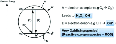 | ||
| Fig. 1 Generation of reactive oxygen species (ROS) on a semiconductor photocatalyst under irradiation. | ||
When designing a photocatalyst for water purification, the aim is usually to use the semiconductor to produce reactive oxygen species (ROS) which carry out the degradation of organic or bacteriological contaminants.13,14 It is key therefore to understand the energetics of the redox processes which allow ROS to form at semiconductors surfaces, a summary of which is given in Table 1.
| Number | ROS generating redox reaction | Redox potential (V vs. NHE)13,90 |
|---|---|---|
| 1 | O2 + ecb− → O2− | −0.33 |
| 2 | O2 + H+ + ecb− → HO2˙ | −0.05 |
| 3 | HO2˙ + H+ + ecb− → H2O2 | 1.44 |
| 4 | O2 + 2ecb− + 2H+ → H2O2 | 0.695 |
| 5 | H2O2 + H+ + ecb− → OH˙ + H2O | 1.14 |
| 6 | OHadsorbed− + hvb+ → OHadsorbed˙ | 1.6 |
| 7 | OHfree− + hvb+ → OHfree˙ | 2.72 |
It is worthwhile to note the upper and lower extremes of these processes and keep them in mind when designing a new photocatalytic material. For instance, the reduction of oxygen (1) is a key step in scavenging photogenerated electrons from the excited semiconductor, which may occur at potentials more negative than the conduction band minima of some semiconductors. In such cases, lowering the pH can be used to promote the reduction of oxygen to the hydroperoxyl radical (2),13 or loading with a noble metal co-catalyst to allow the 2-electron reduction of oxygen to hydrogen peroxide (4).15 When considering the valence band holes, hydroxyl radicals can be generated from surface hydroxide groups. For complete mineralisation of organic material, hydroxyl radicals are generally required due to their high oxidising power,16 and as such there has been considerable interest in the literature upon their generation.17 While producing hydroxyl radicals adsorbed onto the surface (6) requires only a moderately oxidising hole, to generate free hydroxyl radicals desorbed from the surface (7) requires a significantly deeper valence band,18 with implications for the degradation of adsorbing vs. non-adsorbing pollutants.19 This highlights an important factor which should be considered when designing new photocatalytic materials; there is a trade-off between electrochemical driving force for surface redox reactions and the desire to reduce the energy of light used. Materials which use cheap visible light sources and/or solar irradiation are attractive but may be unable to form the more oxidising ROS species effectively. Accessing such highly oxidising ROS has been noted as a viable route to degrade persistent micropollutants,20 toxic organic contaminants which are not removed by current water treatment strategies. Hence, at the nanoscale, the process can be understood relatively simply, however to apply these processes in practice implementation barriers must be overcome, which will be the focus of the remainder of this perspective.
Designing applicable materials
A huge number of novel materials has been developed in the field of photocatalytic water purification,5,21 with new papers being published frequently describing new ways of improving photocatalytic performances. Sometimes overlooked however is the coupling of improved photocatalytic performance with methods by which the material may be applied easily in practice. Much of the published work overlooks this and is carried out without consideration of a target use. Such a disconnect between laboratory and real-world application in a field so closely aligned with a clear potential case for implementation is detrimental to its progress.High efficiency photocatalysts are typically nanoscale materials due to the aforementioned short lifetimes of photogenerated charges.7 Separation of such materials on the laboratory scale is simple enough, with centrifugation being the most commonly applied technique.22 However, when looking to apply such materials on a larger scale this becomes impractical. Removal of nanomaterials from drinking water is key not only for material recovery and re-use, but also from an environmental perspective. While many of the semiconductors used in photocatalysis are considered non-toxic, there are questions being raised as to their toxicity when present in nanoparticulate forms.23 Simple methods of separation and re-use should therefore be an integral part of material design in this area.
Magnetically separable nanoparticles
One way in which simple separation of nanomaterials from solution can be achieved is to use either a photocatalyst with magnetic properties, or to form a composite of the active photocatalyst with such a material. Separation of such materials from solution can be simply achieved using an inexpensive bar magnet as shown in Fig. 2. In this way the good mass transport of a suspension is retained during photocatalytic treatment, but the impractical separation step is simplified somewhat. As magnetisation must be possible under ambient conditions, the most widely reported materials for this purpose are iron based in nature, typically magnetite24,25 or ferrite type26,27 materials. A selection of recently reported materials is given in Table 2. These examples demonstrate the various levels of nanoparticle engineering required to arrive at a highly efficient photocatalyst system. Although magnetite and ferrite materials have the potential to be photocatalytically active in their own right, the efficiency of these materials alone is low due to rapid charge recombination in the pure semiconductor. The work of Shekofteh-Gohari et al.24 demonstrated that magnetite may be incorporated simply as support material for a photocatalytic ZnO, AgBr and Ag3VO4 composite, and may not necessarily take part in the photocatalytic mechanism.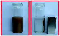 | ||
| Fig. 2 Magnetic separation of a magnetic nanocomposite post use. Image reproduced from ref. 24 with permission from The Royal Society of Chemistry. | ||
| Material (magnetic component in bold) | Model pollutant | Light source | Photocatalytic degradation measure |
|---|---|---|---|
| ZnO/AgBr/Fe3O4/Ag3VO4 (ref. 24) | Rhodamine B | 50 W LED | 0.029 min−1 |
| NiAl layered double hydroxide/Fe3O4–reduced graphene oxide91 | Ciprofloxacin | 500 W Xe lamp (>420 nm filter) | 0.0235 min−1 |
| Fe 3 O 4 –TiO2 (ref. 25) | Reactive brilliant red 3 | 300 W Xe lamp | 0.03–0.035 min−1 |
| Bi2MoO6/ZnFe2O4 (ref. 26) | Rhodamine B | 150 W Xe lamp | 0.0034 min−1 |
| CoFe 2 O 4 –PANI (ref. 92) | Methyl orange | 10 W LED | 85% degradation in 2 hours |
| C3N4@MnFe2O4–graphene27 | Various antibiotics | 300 W Xe lamp (>400 nm filter) | 0.017–0.042 min−1 |
Examples exist in the literature where the inclusion of a magnetic semiconductor reduces activity28 due to the light filtering or migration of charges from the active photocatalysts to an inert magnetic material. Successes in overcoming this unfavourable charge migration have been achieved by introduction of barrier layers between active and inactive magnetic support materials29 as shown in Fig. 3.
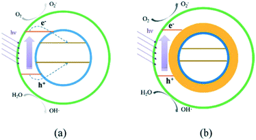 | ||
| Fig. 3 Charge transfer in a magnetic composite without (a) and with (b) a blocking interlayer. Image reproduced from ref. 29 with permission from The Royal Society of Chemistry. | ||
Without using a barrier (Fig. 3a), charges can migrate to the magnetic support, where they may be unable to take part in useful surface reactions either due to mismatching of conduction and valence band energy levels, or simply due to being blocked from solution by the outer layers. When an interlayer is introduced (Fig. 3b), this charge migration is suppressed and photocatalytic ROS generation on the active material surface can go ahead.
Where magnetite and ferrite materials are used as light harvesting materials they are often combined in a composite with conductive carbonaceous materials to allow a degree of charge separation between the two materials. A recent report by Xiao et al.30 has suggested that carbon nitride (C3N4), a material commonly used in this manner, may be itself degraded by ROS generated in the photocatalytic reaction as shown in Fig. 4. While good stability of photocatalyst systems containing C3N4 have been noted,31 the results of Xiao et al. suggest that low levels of secondary pollutants may be introduced into the treated water in this way, suggesting that this may be a material to avoid for water treatment. The degradation fragments identified by the authors involve the breaking of C–N bonds, suggesting that degradation in this manner may be specific to C3N4. Therefore, it may be the case that this does not occur when the related materials graphene or reduced graphene oxide are used, however detailed studies on photocatalytic stabilities of such systems have not been undertaken to date.
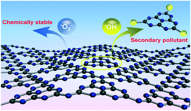 | ||
| Fig. 4 ROS attack on C3N4 as proposed by Xiao et al. reprinted with permission from ref. 30. Copyright 2017 American Chemical Society. | ||
Immobilised nanomaterials
Immobilisation of a nanomaterial on a macroscopic support gives a simple route to separation of the photocatalyst from solution. Supports such as glass, plastic, or metals have been described in the literature for this purpose.32,33 A great many reports have arisen focusing on vacuum techniques for photocatalyst deposition. These methods are well established and recent reviews have been published describing such processes.34,35 This section will instead focus on recent developments in simple solution processing techniques for immobilisation of photocatalysts. In Table 3 is given a selection of immobilised photocatalyst systems. Immobilisation on glass slides is a commonly applied method, where a glass substrate is coated with a sol precursor to a photocatalytic material, which becomes the active phase on heat treatment. Yaparatne et al.36 recently used such a method to prepare TiO2–SiO2 films on glass slides. Coating suspensions containing sols have been found to improve the film robustness greatly by controlling aggregation.37 While SiO2 and other such binders may not be photocatalytically active material under normal conditions, their inclusion is hugely beneficial when producing a well-adhered film photocatalyst. SiO2 or TiO2 are the most commonly applied binder sols, however other materials with superior or complementary photocatalytic action are known to be prepared by sol–gel routes,38 which could impart both a robust film and improved photocatalytic activity.| Photocatalytic material | Support | Photocatalyst deposition method | Model pollutant | Light source/applied bias | Photocatalytic degradation measure |
|---|---|---|---|---|---|
| ZnO (ref. 49) | Polypropylene plates | Epoxy sealer method | Compost leachate | 32 W UVc lamps | 61% COD removal in 4 hours |
| TiO2 (ref. 52) | Optical Fibres | Dip coating | Chlorobenzoic acid | 365 nm LEDs | 5.2 × 10⁻⁵ s−1 |
| TiO2–SiO2 (ref. 36) | Microscope glass slides | Dip coating | Methylisoborneol | 350 nm lamps | 3.22 × 10⁻² min−1 |
| Geosmin | 2.72 × 10⁻² min−1 | ||||
| BiOCl–TiO2 (ref. 93) | FTO glass | Hydrothermal | Rhodamine B | 150 W xenon lamp | 2.59 h−1 |
| TiO2 (ref. 40) | FTO glass | Hydrothermal | Methylene blue | Sim. Solar light/1 V vs. RHE | 94% removal in 90 min |
| Orange II | 77% removal in 4 hours | ||||
| C3N4–TiO2 (ref. 41) | Ti foil | Anodisation | Phenol | 500 W Xe lamp/1–4 V vs. RHE | 100% removal in 150 min |
| Au–polydopamine–Bi2MoO6–TiO2 (ref. 45) | Ti foil | Anodisation | Methylene blue | 300 W hg lamp + 300 W Xe lamp | 0.0203 min−1 |
| Phenol | 0.0126 min−1 | ||||
| Bisphenol A | 0.0197 min−1 | ||||
| TiO2-polydopamine48 | Glass rod & Capillary Fibres | In situ polymerisation | Geosmin | 350 W Xe lamp | Up to 91.5% removal in 2 hours |
| Fluorene | Up to 99% removal in 2 hours | ||||
| Cu2O-CNT-Si nanopillars43 | Si | Electrodeposition | Methylene blue | 100 W halogen (>400 nm) | 86% removal in 2 hours |
| Bi–TiO2 (ref. 44) | Ti foil | Electrodeposition | Acid orange II | 1000 W Xe lamp (>400 nm) | 30% removal in 2 hours |
| Bi2O3–TiO2 | 45% removal in 2 hours | ||||
| BiOI–TiO2 | 60% removal in 2 hours |
A somewhat lower temperature method by which TiO2 photocatalysts can be immobilised on glass substrates is by hydrothermal synthesis. Conductive fluorine doped tin oxide (FTO) substrates is used in such cases due to lattice matching between TiO2 and FTO,39 which allows access to photoelectrocatalytic and electrocatalytic processes. Recently Woo An et al.40 investigated photocatalytic and photoelectrocatalytic performances of hydrothermally grown TiO2 nanorod arrays. The authors concluded that the aspect ratio of the prepared nanorods was key in the activity by controlling the degree of light trapping and charge transport in the film as shown in Fig. 5. While best efficiencies were observed under an applied bias, improvements to light trapping by the nanorod morphologies was found to give reasonable photocatalytic efficiencies without need for external power and addition of electrolytes.
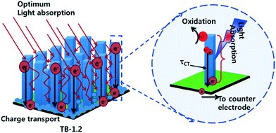 | ||
| Fig. 5 Light trapping and charge transport mechanism proposed by Woo An et al. reprinted from ref. 40. Copyright 2018, with permission from Elsevier. | ||
To improve light trapping and increase surface area further, nanomaterials with tube-like morphologies can be prepared. Recently much work has been undertaken in producing TiO2 nanotubes by anodisation of Ti foils. Employing high potentials and corrosive solvents, etching of the Ti substrate and subsequent annealing leaves tubes of TiO2 immobilised on the conductive foil surface. Such a technique has been capitalised upon by work such as that of Wang et al.41 to degrade phenol. While the vast majority of anodisation work in the literature focuses upon titania, it is also possible to start from an alloy of titanium and other metals, which upon anodisation gives composite materials. Mazierski et al.42 demonstrated this in the fabrication of TiO2–Ag2O nanotube arrays interlaced with Ag nanoparticles. While the use of Ag does not lend itself to cheap applications, this work shows the potential for the use of alloys to generate photocatalytic materials in this way.
The conductive nature of substrates can also be applied in producing new photocatalyst materials. Techniques such as electropolymerisation and electrodeposition have been used to produce new composite materials on conducting photocatalytic films. Electrodeposition methods can give close control over the particle morphologies and interconnection by changing the potentials used, and the way in which the potential is applied. A recent report by Sun et al.43 demonstrates the fine control of such a method, where a pulsed electrodeposition method is used to grow nanocubes of Cu2O onto carbon nanotube (CNT) fibres suspended between Si nanopillars as shown in Fig. 6.
 | ||
| Fig. 6 Schematic representation of the fabrication process including electrodeposition of suspended CuO on CNT fibres. Image reproduced from ref. 43 with permission from The Royal Society of Chemistry. | ||
This technique may also give rise to divergent synthetic strategies, where electrodeposition of a common precursor can lead to multiple products. As Sun et al. noted, their method has been found to produce CuO in some systems rather than Cu2O, however in other cases a more varied product scope has been demonstrated. Yuan et al.44 found that they were able to deposit Bi nanoparticles on TiO2 nanotubes, which, while active in their own right for the degradation of acid orange II, could be converted by simple solution processing or thermal treatments to give BiOI–TiO2 or Bi2O3–TiO2 composites with better photocatalytic activity.
Cai et al.45 recently used electropolymerisation to produce a polydopamine layer in a composite of Au–Bi2MoO6 on TiO2 nanotube arrays. In this work, the polydopamine was used as an anchoring material and also to facilitate the growth of the Au NP, however it has been suggested that polydopamine may contribute to the photocatalytic production of hydroxyl radicals,46 and may sensitise semiconductors such as TiO2 in addition.47 Polydopamine has also been used as an immobilisation method of TiO2 on glass substrates in its own right by Liu et al.48 as shown in Fig. 7. The authors apply an in situ polymerisation coating technique to coat glass rods and capillary fibres with TiO2-polydopamine composites, where the TiO2 is firstly coated with polydopamine and then “caught” on the surface of the substrate during polymerisation. This material was found to be highly effective for the degradation of fluorene and geosmin under visible and UV irradiation.
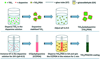 | ||
| Fig. 7 Polymerisation coating of glass tubes by polydopamine coating of TiO2 as reported by Liu et al. reprinted with permission from ref. 48. Copyright 2017 American Chemical Society. | ||
Incorporation of polymers into photocatalytic materials has been studied thoroughly, however the use of simple polymeric substrates have also gained attention in recent years. Use of plastic is somewhat complicated by the inability to heat most plastics to the temperatures required for most deposition methods of common photocatalysts. The work of Ranjbari et al.49 exemplifies a way in which this thermal instability may be overcome. They use a method by which pre-synthesised ZnO particles are immobilised through use of an adhesive layer, thereby avoiding any calcination or annealing steps. Their work demonstrates that it is possible to retain the favourable characteristics of high temperature syntheses (i.e. high crystallinity, porosity, morphologies, desirable phases) and immobilise the material post-synthesis in a simple manner.
Many different polymers in the literature have been reported as inactive supports, or to contribute to the photocatalytic activity of another material by introducing mechanisms for charge separation, or to act as photocatalysts in their own right.50 However, organic materials are highly unlikely to be stable in the presence of photocatalytically generated ROS. As such, thorough stability testing should be undertaken upon such materials when ascertaining their practical utility, alongside determination whether secondary pollutants are being introduced during photocatalytic treatment.
In addition to being easily separable, immobilised photocatalyst systems have been shown to improve light delivery to the photocatalyst surface through reducing the inner filtering which occurs in slurry reactors.51 The work of Tugaoen et al.52 has recently demonstrated the direct deposition of photocatalytic TiO2 onto the surface of optical fibres, providing a route for direct excitation from within the support as shown in Fig. 8. By capitalising on the difference in refractive index at the optical fibre/TiO2 interface, the fibre optic acts as both a support and a route by which light can be introduced into the system. Such a system removes any potential shadowing or parasitic absorption by the pollutant solution, and as light is introduced directly into the fibre, less is leaked into the surroundings.
 | ||
| Fig. 8 Light delivery mechanism in a TiO2 coated fibre optic developed by Tugaoen et al. reprinted from ref. 52, copyright 2017, with permission from Elsevier. | ||
Reactor systems
Immobilisation of novel photocatalyst materials is still relatively uncommon in the literature, where batch slurry systems are favoured, however reports exist of a variety of photoreactor types using industry standard TiO2 or ZnO materials. A selection of recent reports on photocatalytic reactor designs is given in Table 4.| Photocatalytic material | Reactor design | Model pollutant | Light source | Degradation measure | Notes |
|---|---|---|---|---|---|
| ZnO (ref. 54) | Microfluidic | Methyl orange | 100 W UV lamp | Up to ∼1.2 min−1 | 2 order of magnitude improvement over batch |
| TiO2 (ref. 55) | Fixed bed | Clofibric acid | Hg lamp | 1.12 min−1 | Efficiency lower, but comparable, to slurry |
| Fixed film | 1.28 min−1 | ||||
| ZnO–TiO2 (ref. 56) | Fixed film | Methyl orange | UV lamp (2.61 mW cm−2) | 0.0072 h−1 | Photoleaching under UV irradiation |
| TiO2 (ref. 57) | Rotating disk | Phenol | UV light (1.782 mW cm−2) | 0.01313 min−1 | Jet stream impinging onto photocatalyst surface |
| C3N4–TiO2 (ref. 59) | Membrane | Sulfamethoxazole | 300 W Xe lamp | 69% removal in 30 hours | Recirculating system |
| C3N4 (ref. 60) | Membrane | Rhodamine B | 300 W Xe lamp (>400 nm filter) | 18% to 92% removal after 1 to 7 passes | Multiple stage system |
| CuO–TiO2 (ref. 63) | Foam | Methyl orange | Xe lamp (100 mW cm−2) | 0.1487 min−1 | Addition of H2O2, “Fenton-like” reactivity on Cu |
| BiOBr–TiO2 (ref. 64) | Unpowered fixed bed | Rhodamine | Real solar (30–60 mW cm−2) | 305.6 L h−1 m−2 | Flow produced by capillary force |
Microfluidic devices have gained a significant amount of attention in recent years due to the improvements in mass transport and reduction in parasitic light filtering which exists in larger systems.53 In such a system a pollutant solution is pumped through micro-scale channels coated with photocatalysts while irradiating through a transparent glass or plastic face. Devices may be single channel, but more commonly multi-channel systems such as that shown in Fig. 9 are used. Zhao et al.54 recently studied the effectiveness of a ZnO nanorod based system formed using a combination of sol gel and hydrothermal syntheses in a microfluidic chamber type reactor. The authors of this work observed a large improvement over the batch type process, ascribing this to improved mass transport when run in flow. While the use of micro-scale fluidic devices has gained popularity due to these reasons, success has been achieved with larger scale flow systems. The use of fixed bed and fixed film reactors using TiO2 has been proven to be effective for pollutant degradation, with examples existing of comparable activity being displayed versus slurry reactors.55
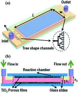 | ||
| Fig. 9 Schematic of a typical microfluidic device with multiple channels in a tree like distribution. Image reproduced from ref. 53 with permission from The Royal Society of Chemistry. | ||
An important aspect of such flow systems which may sometimes be overlooked in the literature is the stability of the photocatalytic material under the test conditions. İkizler et al.56 found that Zn from ZnO nanorods could be leached into the test solution under irradiation due to photodissolution of Zn, but were able to abate this somewhat by introduction of a protective TiO2 layer. While the possibility of leaching or flaking from a film surface is always present in any immobilised photocatalytic test system, under flow this can be exacerbated by the rate of water being passed over the film. A recent example from Jafarikojour et al.57 applied an impinging jet stream of pollutant, with the aim of improving mass transfer rates. This technique involves introducing the pollutant rapidly in a jet of water onto the photocatalyst disk surface while rotating (Fig. 10), giving a thin layer of pollutant solution covering the photocatalyst surface which is rapidly degraded. To make use of such a technique the photocatalyst must be adhered strongly to the disk surface to be successfully retained. While jet impinging of the pollutant is quite an extreme measure, this work demonstrates the importance of robustness of the immobilisation and stability of the materials to producing effective photocatalyst systems, where high force methods may be needed to give high degradation rates.
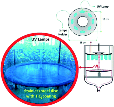 | ||
| Fig. 10 Jet impinging of a pollutant solution onto a TiO2 coated disk surface in the set up. Reprinted from ref. 57, copyright 2017, with permission from Elsevier. | ||
Membrane type reactors, where the photocatalytic material is immobilised on a porous support through which contaminated water is passed, have been studied due to the large quantity of prior work surrounding the preparation and characterisation of membrane filters.58 Forcing a pollutant solution through such a material typically gives short contact times between the photocatalyst and pollutant molecules, resulting in poor performance in a single pass. Research in this area typically has used multiple stage or recirculating systems to achieve good degradation efficiencies. Yu et al.59 used recirculation over a membrane of C3N4–TiO2 on a polymer support to degrade a model anti-biotic under UV/visible irradiation as shown in Fig. 11. While the membrane was found to be robust under the prolonged mechanical stresses in the reactor, some instability under irradiation was noted by the authors. A loss in tensile strength of the membrane was concluded to be due to hydroxyl radical attack or photolysis of the organic support material. While Yu et al. postulated that membranes do not require very high mechanical strengths to be viable, a question that should be posed is the safety of the polymer degradation products in the downstream water. A more robust carbon fibre cloth supported C3N4 photocatalyst was reported by Shen et al.60 recently. Multiple stage treatment was used to increase the degradation of rhodamine B, going from around 18% degradation in a single photocatalytic/filtration stage, to 92% after passing through seven membrane systems fitted in series as shown in Fig. 12.
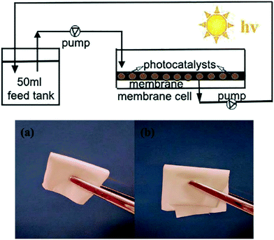 | ||
| Fig. 11 Schematic of the recirculation membrane photoreactor system used by Yu et al. and the flexibility of the polymeric membrane used. Reprinted from ref. 59, copyright 2018, with permission from Elsevier. | ||
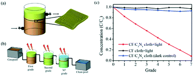 | ||
| Fig. 12 Photocatalytic membrane system devised by Shen et al. showing (a) a single grade system where pollutant is pumped through the membrane, (b) the connection of several grade systems in series and (c) the improvement in Rhodamine B removal after multiple degradation grades. Reprinted from ref. 60, copyright 2017, with permission from Elsevier. | ||
Several repeat measurements were undertaken with no loss in activity, and no observed change in the structure or morphology noted by the authors.
It is noteworthy that flow systems such as those described above are relatively complex pieces of equipment, which may not be viable in some areas of the planet where the skills and funds needed for maintenance are not available. In such areas point of use purification of drinking water sources would be a logical starting point,61 which has been noted as an area where photocatalysis could give a degree of treatment where other techniques are not possible.62 Therefore, low tech reactor designs in these areas may be preferable. A simple TiO2 coated carbon foam based microreactor has been developed by Zhu et al.63 In the operation of this microreactor the foam acts as a sponge to soak up pollutant solutions, which can be photocatalytically purified before simply squeezing the foam to release the decontaminated water as shown in Fig. 13.
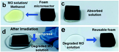 | ||
| Fig. 13 Uptake of MO solution by soaking of the foam microreactor developed by Zhu et al. and subsequent regeneration of the foam leaving the purified solution. Reprinted from ref. 63, copyright 2015, with permission from Wiley-VCH. | ||
They note that no mechanical mixing is required in this set up due to channelling of the pollutant solution by the foam to the TiO2 surface. As such, this type of microreactor could well be particularly effective in an environment with little or no access to electricity, where a powered agitation or flow system may not be viable. Similarly, Mei et al.64 recently demonstrated the use of an unpowered flow reactor system using a carbon cloth framework as shown in Fig. 14. Using capillary force, the authors were able to drive the flow of a pollutant solution over the photocatalyst surface while under solar irradiation, producing a flow system without any external electrical input. Such innovative systems fit the niche of photocatalysis in remote “off grid” communities perfectly.
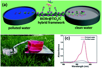 | ||
| Fig. 14 (a) Schematic image of the un-powered flow reactor used by Mei et al. (b) Photograph of the system in operation under solar irradiation and (c) the removal of rhodamine B using the system. Image reproduced from ref. 64 with permission from The Royal Society of Chemistry. | ||
While a huge number of reactor designs and optimisation studies upon these reactors are being published continually, the work of Mei et al. described above is somewhat in the minority in that it makes use of a more complex material than the industry standards. A great many reports are also being generated on new materials with reportedly higher efficiencies than the standard P25 TiO2 photocatalysts, yet most are not designed with any particular application or reactor system in mind. This is a common disconnect in the field of photocatalytic water treatment, where application is not considered during the material development stage, and few make any effort to produce working reactors with novel materials. There is therefore a clear potential for collaborative efforts to develop new materials with immobilisation and reactor use in mind, and thereby take steps toward a useable system.
Are current testing methods applicable?
Simply by examining the information contained in Tables 2–4 in this review it becomes clear that there is a huge array of different testing conditions used in the literature. Light sources used to power photocatalytic reactions often differ in terms of their emission wavelengths and intensities, and there is no clear consensus on which pollutants should be used to test photocatalysts. Thus, even after thorough testing of a new material it can be very difficult or impossible to compare to the results of others in a meaningful way.While there is typically a high quality of control experiments run using materials from within a single piece of research, one further control method which should be applied is to compare all prepared materials to an industrial standard such as P25,65 even if the prepared material is not a TiO2 based photocatalyst. The percentage improvement over this standard then becomes the metric which can be used to compare various materials. This can then be compared to others who have carried out the same test, and thus account to some extent for differences in set up and light source. Often comparisons are made to a synthesised control material (i.e. TiO2 synthesised in parallel in the laboratory), which is worthwhile but does not allow for comparison between laboratories. Testing upon P25 is applied inconsistently in the literature however, and therefore becomes a difficult comparison to make. It also breaks down somewhat when the goal of a piece of research is to impart visible light sensitisation upon a UV-absorbing material, as the light source for such a test will be fundamentally incompatible with most P25. In these cases, the improvement of the sensitised material over P25 will be misleadingly high. It has been suggested that nitrogen-doped TiO2 control could be used as a standard for visible light performance,66 however the use of this material is even more infrequent than that of the normal P25 standard. Thus, the use of such control experiments should always be encouraged, as the quality of comparison which can be made through them relies upon their widespread use. If a consensus can be reached on the material and conditions used for UV, UV-visible and visible active photocatalysts, then comparison of performance could be improved significantly.
A large variety of different model pollutants has been used to determine activity in photocatalytic systems. Pollutants such as agricultural molecules, drugs, explosives or industrial waste products have been studied, but by far the most common class of molecules used in testing are dyes.67 While the textile industry is indeed reckoned to be the cause of much of the worlds contaminated water,68 questions must be raised about the validity of the use of dyes in ascertaining performance. For truly applicable systems to be developed, thorough reliable testing methods should be encouraged, which dyes may not satisfy. While it is often overlooked, a process known as self-sensitisation or dye-sensitisation by dye model pollutants can give entirely misleading photocatalytic performance results for a new material.69 A schematic representation of this effect is given in Fig. 15.
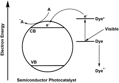 | ||
| Fig. 15 Mechanism of self-sensitisation by a dye molecule on the surface of a semiconductor photocatalyst. | ||
In this mechanism, excitation of the model pollutant facilitates ROS generation, bypassing the semiconductors used. Therefore, activity is not dependent upon excitation of the photocatalyst material at all and is simply determined by the properties of the dye. As the absorption is dependent upon the dye model pollutant and the photocatalyst used, the optical properties of the dye and its surface adsorption become important in determining activity,22 and thus the activity becomes specific to that dye pollutant under the irradiation conditions used. This is not necessarily a problem if activity is clearly claimed solely for the dye pollutant in question, however issues arise when general performance is assumed based on a dye decolourisation test alone, or when comparisons between different dyes are attempted.
It is possible to overcome this sensitisation effect by either applying a light source which has no overlap with the dye absorption, or simply studying the removal of a colourless pollutant. A selection of recent examples of photocatalysts tested where self-sensitisation is discussed is given in Table 5. This self-sensitisation effect has led to examples of visible inactive materials demonstrating activity under visible light,70 however publications are continually forthcoming where this effect is not addressed sufficiently. Recently Cates et al.71 surveyed several reported upconverting lanthanide based phosphors under visible light, and determined that these examples could not give the reported improvements in activity based on their upconverting properties. They conclude that such examples are likely down to self-sensitisation as shown in Fig. 16, and thus much of the field of upconverting photocatalyst for water purification are likely unreliable for this reason. The study of Cates et al. is thorough, but it is clear that this problem goes beyond upconverting photocatalysts, and questions must be raised going forward about the true activity of reported photocatalysts. A further reason that tests upon dyes may be unreliable is the measurement of decolourisation rather than degradation. Many studies exist where degradation is claimed, however the evidence provided for this relies upon a simple loss of colour of the solution. It is possible that complete degradation does indeed occur in these cases; recent work by Hao et al.72 observed that the mineralisation of methyl orange closely matched the decolourisation in their system, however this is not always the case, and is rarely investigated. A simple change in the chromophore may well be occurring, leaving most of the molecule intact, but appearing as if complete degradation has occurred. Indeed, examples such as that of Jiang et al.73 and Zhang et al.74 demonstrate that dyes such as Rhodamine B can undergo slight modifications such as de-ethylation under photocatalytic conditions, causing a shift of the absorption peak as shown in Fig. 17.
| Photocatalytic material | Light source | Model pollutants | Degradation measure |
|---|---|---|---|
| Bi3O4Br–Bi2O3 (ref. 94) | 350 W Xe lamp (>400 nm) | Methyl orange | 0.03703 min−1 |
| Phenol | 0.28826 h−1 | ||
| WO3–vanadium phosphate95 | 180 W UV/visible irradiation chamber | Rhodamine B | 100% removal in 10 minutes |
| Phenol | 60% removal in 10 minutes | ||
| SrTiO3–Ag–AgCl (ref. 96) | 300 W Xe lamp (>420 nm) | Various dyes | 93–96% removal in 30–70 minutes |
| Bisphenol A | 83% removal in 4 hours | ||
| Phenol | 70% removal in 4 hours | ||
| ZnO–reduced graphene oxide97 | 300 W Xe lamp | Rhodamine B | 0.291 min−1 |
| Phenol | 5.56 × 10⁻² min−1 | ||
| Boron nitride–TiO2 (ref. 98) | Xe lamp producing 350 W m−2 | Rhodamine B | 99% removal in 6 hours |
| Phenol | 83% removal in 30 hours | ||
| Boron nitride–BiOI (ref. 99) | 350 W Xe lamp (>420 nm) | Methylene blue & Rhodamine B | ∼90% removal in 100 minutes |
| 4-Chlorophenol | ∼75% removal in 150 minutes | ||
| BiOBr–WO3 (ref. 100) | 300 W Xe lamp (>400 nm) | Methyl orange | 61.9% removal in 3 hours |
| Rhodamine B | 100% removal in 20 minutes | ||
| 4-Chlorophenol | 71% removal in 6 hours |
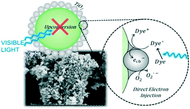 | ||
| Fig. 16 Schematic representation of the lack of activity derived from upconversion in upconverting nanocomposites. Reprinted with permission from ref. 71. Copyright 2018 American Chemical Society. | ||
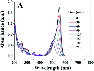 | ||
| Fig. 17 Spectral changes of Rhodamine B under photocatalytic conditions showing blue shift of peak. Image reproduced from ref. 73 with permission from The Royal Society of Chemistry. | ||
In these examples, there is a clear difference in rate of decolourisation and degradation, but in other cases it may not be clear as the product formed is colourless. While studying the degradation of methyl orange, Deng et al.75 recently found that the rate of mineralisation was significantly slower than decolourisation using their BiOBr photocatalyst, and that changes to their reaction conditions which were beneficial for decolourisation were in fact decreasing the mineralisation performance. Incomplete degradation giving decolourisation or shifts in absorption maxima of dyes may not even involve significant structural changes. Methylene blue for example is known to be able to undergo a two-electron reduction to give the colourless leuco-methylene blue76 as shown in Fig. 18, which is a possible reaction pathway in photocatalytic systems.77
Combinations of self-sensitisation and decolourisation processes such as this may be complicated even further by electron transfer from dyes to other species in water such as dissolved oxygen. Mitoraj et al.78 noted that methylene blue can decolourise in several different ways in the presence of InVO4/BiVO4 composites depending on the wavelength of light used, including electron transfer to oxygen. These processes may be occurring simultaneously, and the true photocatalytic degradation derived from the photocatalyst itself is almost impossible to ascertain.
Thus, while literature examples of photocatalysts tested against dyes are, and continue to be, the most common to date, claims based on a test against a single dye molecule should be treated with caution. Care should be taken to ensure clarity of the claims being made in any published work; there is however a trend to conflate decolourisation with non-specific performance and total mineralisation, which should be avoided.
The question then remains: what can be done to overcome these inconsistencies and thus improve the applicability of photocatalysts?
While dye models are particularly prone to inconsistencies, molecules of other classes are not immune from giving misleading results, and as such testing against as wide and diverse a set of pollutants as possible is key. Good examples in the literature address this by focusing upon a subset of organic pollutants such as drug molecules,79 explosives80 or agricultural chemicals81 and study the degradation of numerous examples. In doing so, these studies provide a baseline of activity against the molecule classes tested, which gives a much more thorough and reliable proof of activity. The European Union Water Framework Directive and USA Environmental Protection Agency both have released lists82,83 of compounds that are identified as problematic, giving a host of different molecules for which there is a clear avenue of inquiry for photocatalytic treatment. In addition, there exist numerous surveys of water contaminants present in different areas of the world,84–88 which identify numerous organic contaminants which would be logical test subjects. Thus, there exist many compounds which can be used for testing which have clear real-world applications. While there is still a need for the development of new photocatalytic materials and reactor systems, there is a gap which has been relatively overlooked in applying new materials to the degradation of these relevant compounds.
A further factor which should be emphasised is the recycling of a material or repeat testing of a reactor setup. Typically, such tests are carried out in the published work with reasonable consistency, with more in-depth studies such as those discussed earlier in this perspective by Xiao et al.30 and Yu et al.59 highlighting specific stability concerns. Generally, literature examples re-use a material or system up to around 10 complete degradation cycles to establish stability or lack thereof, meaning that stability will be tested on the order of a few hours. However, it should be remembered that water purification is a large scale continuous process, and as such the longer-term stability is key. Testing this level of stability cannot realistically be expected using standard conditions but is important to photocatalysis being demonstrated to be viable. Lessons can be learned from the standardised stability testing common in the solar cell field,89 where accelerated stability tests are used to estimate lifetime. There exists an opportunity in photocatalytic water purification to establish such a stability testing regime which can demonstrate stability on longer timescales.
Conclusions
To summarise, water purification is a critical problem, which is likely to grow in coming years. Photocatalytic purification using semiconductors has emerged as a method to remove contamination from water, and much work has been undertaken to develop new and more effective materials for this purpose. While increasing efficacy has been the focus of much work to date, new materials which can be simply applied have been reported, but less attention has been brought to them. It is observed that there has been something of a disconnect between the materials development and efforts to produce workable systems. Despite the multitude of new materials reported, reactor designs mostly focus upon standard materials, and as such a clear opportunity exists in the field for those working upon novel materials to work with those aiming to improve reactor designs. Such collaborative efforts are invaluable to inform both partners of the considerations and limitations of each other's systems, and thereby inform future developments. While new photocatalysts have been consistently published, testing methods are somewhat inconsistent. Much of the reported work uses un-realistic or misleading test systems, and in the recent published work reports have arisen questioning some of these results which are highlighted and discussed in this review. Thus, it is the conclusion of this review that if photocatalytic water purification is to become a widespread practical treatment method in the real world then greater focus should be put upon applicability, consistent and thorough testing, and consideration of the target users' needs.Conflicts of interest
There are no conflicts of interest to declare.Acknowledgements
The authors would like to thank the CRITICAT Centre for Doctoral Training (Ph. D. studentship to O. G.; Grant Code: EP/L016419/1).References
- World Health Organisation, Progress on Drinking Water, Sanitation and Hygiene, 2017 Search PubMed.
- The United Nations, Water Scarcity, 2013 Search PubMed.
- L. Hossain, S. K. Sarker and M. S. Khan, Environ. Dev., 2018, 1–11 Search PubMed.
- Y. Valcárcel, A. Valdehíta, E. Becerra, M. López de Alda, A. Gil, M. Gorga, M. Petrovic, D. Barceló and J. M. Navas, Chemosphere, 2018, 201, 388–398 CrossRef PubMed.
- E. Rahmanian, R. Malekfar and M. Pumera, Chem. – Eur. J., 2018, 24, 18–31 CrossRef CAS PubMed.
- J. Low, J. Yu, M. Jaroniec, S. Wageh and A. A. Al-Ghamdi, Adv. Mater., 2017, 29, 1601694 CrossRef PubMed.
- M. R. Hoffmann, S. T. Martin, W. Choi and D. W. Bahnemann, Chem. Rev., 1995, 95, 69–96 CrossRef CAS.
- X. Wang, L. Bai, H. Liu, X. Yu, Y. Yin and C. Gao, Adv. Funct. Mater., 2018, 28, 1704208 CrossRef.
- C. Song, L. Wang, F. Gao and Q. Lu, Chem. - Eur. J., 2016, 22, 6368–6373 CrossRef CAS PubMed.
- Y. Wang, Q. Wang, X. Zhan, F. Wang, M. Safdar and J. He, Nanoscale, 2013, 5, 8326–8339 RSC.
- D. C. Hurum, A. G. Agrios, K. A. Gray, T. Rajh and M. C. Thurnauer, J. Phys. Chem. B, 2003, 107, 4545–4549 CrossRef CAS.
- Y. Sang, H. Liu and A. Umar, ChemCatChem, 2015, 7, 559–573 CrossRef CAS.
- Y. Nosaka and A. Y. Nosaka, Chem. Rev., 2017, 117, 11302–11336 CrossRef CAS PubMed.
- P. Karaolia, I. Michael-Kordatou, E. Hapeshi, C. Drosou, Y. Bertakis, D. Christofilos, G. S. Armatas, L. Sygellou, T. Schwartz, N. P. Xekoukoulotakis and D. Fatta-Kassinos, Appl. Catal., B, 2018, 224, 810–824 CrossRef CAS.
- R. Abe, H. Takami, N. Murakami and B. Ohtani, J. Am. Chem. Soc., 2008, 130, 7780–7781 CrossRef CAS PubMed.
- S. Nagarajan, N. C. Skillen, F. Fina, G. Zhang, C. Randorn, L. A. Lawton, J. T. S. Irvine and P. K. J. Robertson, J. Photochem. Photobiol., A, 2017, 334, 13–19 CrossRef CAS.
- M. R. D. Khaki, M. S. Shafeeyan, A. A. A. Raman and W. M. A. W. Daud, J. Environ. Manage., 2017, 198, 78–94 CrossRef CAS PubMed.
- J. Schneider, M. Matsuoka, M. Takeuchi, J. Zhang, Y. Horiuchi, M. Anpo and D. W. Bahnemann, Chem. Rev., 2014, 114, 9919–9986 CrossRef CAS PubMed.
- W. Kim, T. Tachikawa, G. H. Moon, T. Majima and W. Choi, Angew. Chem., Int. Ed., 2014, 53, 14036–14041 CrossRef CAS PubMed.
- S. Foteinis, J. M. Monteagudo, A. Durán and E. Chatzisymeon, Sci. Total Environ., 2018, 612, 605–612 CrossRef CAS PubMed.
- M. Ge, C. Cao, J. Huang, S. Li, Z. Chen, K.-Q. Zhang, S. S. Al-deyab and Y. Lai, J. Mater. Chem. A, 2016, 4, 6772–6801 RSC.
- X. Li, H. Lin, X. Chen, H. Niu, J. Liu, T. Zhang and F. Qu, Phys. Chem. Chem. Phys., 2016, 18, 9176–9185 RSC.
- A. Gondikas, F. von der Kammer, R. Kaegi, O. Borovinskaya, E. Neubauer, J. Navratilova, A. Praetorius, G. Cornelis and T. Hofmann, Environ. Sci.: Nano, 2018, 5, 313–326 RSC.
- M. Shekofteh-Gohari and A. Habibi-Yangjeh, RSC Adv., 2016, 6, 2402–2413 RSC.
- Q. Sun, Y. Hong, Q. Liu and L. Dong, Appl. Surf. Sci., 2018, 430, 399–406 CrossRef CAS.
- C. Zhao, C. Shao, X. Li, X. Li, R. Tao, X. Zhou and Y. Liu, J. Alloys Compd., 2018, 747, 916–925 CrossRef CAS.
- X. Wang, A. Wang and J. Ma, J. Hazard. Mater., 2017, 336, 81–92 CrossRef CAS PubMed.
- Z. Shi, Y. Xiang, X. Zhang and S. Yao, Photochem. Photobiol., 2011, 87, 626–631 CrossRef CAS PubMed.
- H. Yao, M. Fan, Y. Wang, G. Luo and W. Fei, J. Mater. Chem. A, 2015, 3, 17511–17524 RSC.
- J. Xiao, Q. Han, Y. Xie, J. Yang, Q. Su, Y. Chen and H. Cao, Environ. Sci. Technol., 2017, 51, 13380–13387 CrossRef CAS PubMed.
- J. Fu, J. Yu, C. Jiang and B. Cheng, Adv. Energy Mater., 2018, 8, 1–31 CAS.
- A. Fernández, G. Lassaletta, V. M. Jiménez, A. Justo, A. R. González-Elipe, J.-M. Herrmann, H. Tahiri and Y. Ait-Ichou, Appl. Catal., B, 1995, 7, 49–63 CrossRef.
- A. Di Mauro, M. Cantarella, G. Nicotra, G. Pellegrino, A. Gulino, M. V. Brundo, V. Privitera and G. Impellizzeri, Sci. Rep., 2017, 7, 40895 CrossRef CAS PubMed.
- J.-P. Niemelä, G. Marin and M. Karppinen, Semicond. Sci. Technol., 2017, 32, 093005 CrossRef.
- X. Meng, J. Mater. Chem. A, 2017, 5, 18326–18378 RSC.
- S. Yaparatne, C. P. Tripp and A. Amirbahman, J. Hazard. Mater., 2018, 346, 208–217 CrossRef CAS PubMed.
- Y. Chen and D. D. Dionysiou, Appl. Catal., B, 2006, 62, 255–264 CrossRef CAS.
- D. P. Debecker and P. H. Mutin, Chem. Soc. Rev., 2012, 41, 3624 RSC.
- W.-Q. Wu, B.-X. Lei, H.-S. Rao, Y.-F. Xu, Y.-F. Wang, C.-Y. Su and D.-B. Kuang, Sci. Rep., 2013, 3, 1352 CrossRef PubMed.
- G. W. An, M. A. Mahadik, W. S. Chae, H. G. Kim, M. Cho and J. S. Jang, Appl. Surf. Sci., 2018, 440, 688–699 CrossRef CAS.
- H. Wang, Y. Liang, L. Liu, J. Hu and W. Cui, J. Hazard. Mater., 2018, 344, 369–380 CrossRef CAS PubMed.
- P. Mazierski, A. Malankowska, M. Kobylański, M. Diak, M. Kozak, M. J. Winiarski, T. Klimczuk, W. Lisowski, G. Nowaczyk and A. Zaleska-Medynska, ACS Catal., 2017, 7, 2753–2764 CrossRef CAS.
- Y. Sun, R. Chen, J. Oh, B. Yoo and H. Lee, RSC Adv., 2017, 7, 2880–2883 RSC.
- X. J. Yuan, J. H. Yi, H. J. Wang, H. Yu, S. Q. Zhang and F. Peng, Mater. Chem. Phys., 2017, 196, 237–244 CrossRef CAS.
- J. Cai, J. Huang and Y. Lai, J. Mater. Chem. A, 2017, 5, 16412–16421 RSC.
- Z. Wang, F. Tang, H. Fan, L. Wang and Z. Jin, Langmuir, 2017, 33, 5938–5946 CrossRef CAS PubMed.
- C. Wang, Y. Wu, J. Lu, J. Zhao, J. Cui, X. Wu, Y. Yan and P. Huo, ACS Appl. Mater. Interfaces, 2017, 9, 23687–23697 CrossRef CAS PubMed.
- S. Liu, Q. Hu, J. Qiu, F. Wang, W. Lin, F. Zhu, C. Wei, N. Zhou and G. Ouyang, Environ. Sci. Technol., 2017, 51, 5137–5145 CrossRef CAS PubMed.
- A. Ranjbari and N. Mokhtarani, Appl. Catal., B, 2018, 220, 211–221 CrossRef CAS.
- S. Ghosh, N. A. Kouamé, L. Ramos, S. Remita, A. Dazzi, A. Deniset-Besseau, P. Beaunier, F. Goubard, P.-H. Aubert and H. Remita, Nat. Mater., 2015, 14, 505–511 CrossRef CAS PubMed.
- L. Ling, H. Tugaoen, J. Brame, S. Sinha, C. Li, J. Schoepf, K. Hristovski, J. H. Kim, C. Shang and P. Westerhoff, Environ. Sci. Technol., 2017, 51, 13319–13326 CrossRef CAS PubMed.
- H. O. Tugaoen, S. Garcia-Segura, K. Hristovski and P. Westerhoff, Sci. Total Environ., 2018, 613–614, 1331–1338 CrossRef PubMed.
- N. Wang, X. Zhang, Y. Wang, W. Yu and H. L. W. Chan, Lab Chip, 2014, 14, 1074–1082 RSC.
- P. Zhao, N. Qin, J. Z. Wen and C. L. Ren, Appl. Catal., B, 2017, 209, 468–475 CrossRef CAS.
- A. Manassero, M. L. Satuf and O. M. Alfano, Chem. Eng. J., 2017, 326, 29–36 CrossRef CAS.
- B. İkizler and S. M. Peker, Thin Solid Films, 2016, 605, 232–242 CrossRef.
- M. Jafarikojour, B. Dabir, M. Sohrabi and S. J. Royaee, Chem. Eng. Process., 2017, 121, 215–223 CrossRef CAS.
- M. Paul and S. D. Jons, Polymer, 2016, 103, 417–456 CrossRef CAS.
- S. Yu, Y. Wang, F. Sun, R. Wang and Y. Zhou, Chem. Eng. J., 2018, 337, 183–192 CrossRef CAS.
- X. Shen, T. Zhang, P. Xu, L. Zhang, J. Liu and Z. Chen, Appl. Catal., B, 2017, 219, 425–431 CrossRef CAS.
- J. Mac Mahon and L. W. Gill, Dev. Eng., 2018, 3, 47–59 CrossRef.
- P. Westerhoff, P. Alvarez, Q. Li, J. Gardea-Torresdey and J. Zimmerman, Environ. Sci.: Nano, 2016, 3, 1241–1253 RSC.
- L. Zhu, C. Fu Tan, M. Gao and G. W. Ho, Adv. Mater., 2015, 27, 7713–7719 CrossRef CAS PubMed.
- Y. Mei, Y. Su, Z. Li, S. Bai, M. Yuan, L. Li, Z. Yan, J. Wu and L.-W. Zhu, Dalton Trans., 2017, 46, 347–354 RSC.
- F. Dufour, S. Pigeot-Remy, O. Durupthy, S. Cassaignon, V. Ruaux, S. Torelli, L. Mariey, F. Maugé and C. Chanéac, Appl. Catal., B, 2015, 174–175, 350–360 CrossRef CAS.
- Y. Bi, H. Hu, S. Ouyang, G. Lu, J. Cao and J. Ye, Chem. Commun., 2012, 48, 3748–3750 RSC.
- K. He, G. Chen, G. Zeng, A. Chen, Z. Huang, J. Shi, T. Huang, M. Peng and L. Hu, Appl. Catal., B, 2018, 228, 19–28 CrossRef CAS.
- D. Rawat, V. Mishra and R. S. Sharma, Chemosphere, 2016, 155, 591–605 CrossRef CAS PubMed.
- G. Odling and N. Robertson, ChemPhysChem, 2016, 17, 2872–2880 CrossRef CAS PubMed.
- L. Zhang, C. G. Niu, G. X. Xie, X. J. Wen, X. G. Zhang and G. M. Zeng, ACS Sustainable Chem. Eng., 2017, 5, 4619–4629 CrossRef CAS.
- S. P. Sahu, S. L. Cates, H.-I. Kim, J.-H. Kim and E. L. Cates, Environ. Sci. Technol., 2018, 52, 2973–2980 CrossRef CAS PubMed.
- L. Hao, H. Huang, Y. Guo and Y. Zhang, ACS Sustainable Chem. Eng., 2018, 6, 1848–1862 CrossRef CAS.
- Z. Jiang, W. Wei, D. Mao, C. Chen, Y. Shi, X. Lv and J. Xie, Nanoscale, 2015, 7, 784–797 RSC.
- Y. Zhang, Z. Zhao, J. Chen, L. Cheng, J. Chang, W. Sheng, C. Hu and S. Cao, Appl. Catal., B, 2015, 165, 715–722 CrossRef CAS.
- W. Deng, H. Zhao, F. Pan, X. Feng, B. Jung, A. Abdel-Wahab, B. Batchelor and Y. Li, Environ. Sci. Technol., 2017, 51, 13372–13379 CrossRef CAS PubMed.
- S. Lee and A. Mills, Chem. Commun., 2003, 2366 RSC.
- A. Mills and J. Wang, J. Photochem. Photobiol. A Chem., 1999, 127, 123–134 CrossRef CAS.
- D. Mitoraj, U. Lamdab, W. Kangwansupamonkon, M. Pacia, W. Macyk, N. Wetchakun and R. Beranek, J. Photochem. Photobiol., A, 2018, 366, 103 CrossRef CAS.
- F. Chen, Q. Yang, F. Yao, S. Wang, J. Sun, H. An, K. Yi, Y. Wang, Y. Zhou, L. Wang, X. Li, D. Wang and G. Zeng, J. Catal., 2017, 352, 160–170 CrossRef CAS.
- J. Huang, B. Jin, H. Liu, X. Li, Q. Zhang, S. Chu, R. Peng and S. Chu, J. Mater. Chem. A, 2018, 11424–11434 RSC.
- N. Vela, M. Calín, M. J. Yáñez-Gascón, I. Garrido, G. Pérez-Lucas, J. Fenoll and S. Navarro, J. Photochem. Photobiol., A, 2018, 353, 271–278 CrossRef CAS.
- Priority Substances and Certain Other Pollutants according to Annex II of Directive 2008/105/EC, European Commission Water Framework Directive, 2016, http://ec.europa.eu/environment/water/water-framework/priority_substances.htm Search PubMed.
- United States Environmental Protection Agency, National Primary Drinking Water Regulations, 2018 Search PubMed.
- X. C. Hu, D. Q. Andrews, A. B. Lindstrom, T. A. Bruton, L. A. Schaider, P. Grandjean, R. Lohmann, C. C. Carignan, A. Blum, S. A. Balan, C. P. Higgins and E. M. Sunderland, Environ. Sci. Technol. Lett., 2016, 3, 344–350 CrossRef CAS PubMed.
- C. M. G. Carpenter and D. E. Helbling, Environ. Sci. Technol., 2018, 52, 6187–6196 CrossRef CAS PubMed.
- U. J. Kim and K. Kannan, Environ. Sci. Technol., 2018, 52, 5625–5633 CrossRef CAS PubMed.
- C. Xu, L. Chen, L. You, Z. Xu, L.-F. Ren, K. Yew-Hoong Gin, Y. He and W. Kai, Environ. Sci.: Processes Impacts, 2018, 20, 1030–1045 RSC.
- T. G. Schwanz, M. Llorca, M. Farré and D. Barceló, Sci. Total Environ., 2016, 539, 143–152 CrossRef CAS PubMed.
- A. Tiihonen, K. Miettunen, J. Halme, S. Lepikko, A. Poskela and P. D. Lund, Energy Environ. Sci., 2018, 730–738 RSC.
- W. Y. Teoh, J. A. Scott and R. Amal, J. Phys. Chem. Lett., 2012, 3, 629–639 CrossRef CAS PubMed.
- J. Ni, J. Xue, L. Xie, J. Shen, G. He and H. Chen, Phys. Chem. Chem. Phys., 2017, 20, 414–421 RSC.
- K. N. Kim, H.-R. Jung and W.-J. Lee, J. Photochem. Photobiol., A, 2016, 321, 257–265 CrossRef CAS.
- Y. Shen, X. Yu, W. Lin, Y. Zhu and Y. Zhang, Appl. Surf. Sci., 2017, 399, 67–76 CrossRef CAS.
- J. guo Guo, Y. Liu, Y. juan Hao, Y. lei Li, X. jing Wang, R. hong Liu and F. tang Li, Appl. Catal., B, 2018, 224, 841–853 CrossRef.
- G. C. Behera, N. Biswal and K. Parida, Catal. Today, 2017, 284, 84–91 CrossRef CAS.
- S.-F. Yang, C.-G. Niu, D.-W. Huang, H. Zhang, C. Liang and G.-M. Zeng, Environ. Sci.: Nano, 2017, 4, 585–595 RSC.
- F. Wang, Y. Zhou, X. Pan, B. Lu, J. Huang and Z. Ye, Phys. Chem. Chem. Phys., 2018, 20, 6959–6969 RSC.
- D. Liu, M. Zhang, W. Xie, L. Sun, Y. Chen and W. Lei, Appl. Catal., B, 2017, 207, 72–78 CrossRef CAS.
- D. Liu, Z. Jiang, C. Zhu, K. Qian, Z. Wu and J. Xie, Dalton Trans., 2016, 45, 2505–2516 RSC.
- J. Zhang, L. Zhang, X. Shen, P. Xu and J. Liu, CrystEngComm, 2016, 18, 3856–3865 RSC.
| This journal is © The Royal Society of Chemistry 2019 |

