MOLC. A reversible coarse grained approach using anisotropic beads for the modelling of organic functional materials†
Received
23rd July 2019
, Accepted 19th October 2019
First published on 21st November 2019
Abstract
We describe the development and implementation of a coarse grained (CG) modelling approach where complex organic molecules, and particularly the π-conjugated ones often employed in organic electronics, are modelled in terms of connected sets of attractive–repulsive biaxial Gay–Berne ellipsoidal beads. The CG model is aimed at reproducing realistically large scale morphologies (e.g. up to 100 nm thick films) for the materials involved, while being able to generate, with a back-mapping procedure, atomistic coordinates suitable, with limited effort, to be applied for charge transport calculations. Detailed methodology and an application to the common hole transporter material α-NPD are provided.
1 Introduction
Predicting the molecular organization of organic functional materials, e.g. materials for organic electronics (OE) applications1 or liquid crystals,2 is an extremely important task for the rational design and optimization of their many applications in fields such as organic photovoltaics (OPV), field effect transistors (FET), organic light emitting diodes (OLED) and liquid crystal displays (LCD).2 Much headway in this direction is being provided by atomistic modelling, which represents each molecule, with its appropriate geometry, internal degrees of freedom, and intermolecular interactions, as an ordered collection of suitably interacting attractive–repulsive spheres.3 Internal vibrations, librations and torsions are determined, at least for the isolated molecule in the ground state, with quantum chemistry (QC) calculations at various levels of approximation ranging from density functional theory (DFT) to more sophisticated ab initio methods.4,5 The partial charge on every atom can also be obtained reliably, in the sense of reproducing the electric field around the molecule with a controlled error threshold, with various methods.6,7 These QC investigations of a single molecule, which have been for decades the frontier and the test ground for generations of methodological approaches to solving the Schrödinger equation, have now become nearly standard and available to the average bench chemist, thanks to packages like Gaussian,8 GAMESS,9 ADF,10etc. For instance, the reliability of a number of DFT methods has recently been critically evaluated in terms of reproducibility, giving a comforting outlook, at least for modern codes and pseudopotentials.11
The next and now pressing problem in modelling is that of obtaining the properties not of a single molecule but of a material, e.g. melting and boiling points, morphologies etc. This is absolutely far from trivial, to the point that it was judged “beyond mortal ken” in a famous statement by J. Maddox.12
One of the main problems in realistic material modelling is that of obtaining a set of pairwise “effective” interactions that allows one to include, to some extent at least, the contributions of the other particles surrounding the pair considered.
Such a set of interactions, or “force field” (FF),4 will necessarily be reasonably specific for a class of compounds, rather than universal. It has to be defined in terms of a hopefully small set of parameters to be obtained and tuned by comparison with some suitable experimental data set, but maintain the ability to predict other properties not included in the basket employed as a parameter tuning set and be transferable, if not universally at least to other similar materials. The other problem, having gone this far, is to obtain a sufficient number of equilibrium configurations (or “snapshots”) for the system at a certain temperature (or more generally thermodynamic conditions) in order to calculate observables of interest with reasonable accuracy. From the methodological point of view, the problem can be handled with molecular dynamics (MD) codes, by solving Newton's differential equation of motion for all the atoms, and again various well developed packages exist for that, e.g. LAMMPS,13 GROMACS,14 and NAMD.15 Although the problem is well defined, its cost in terms of computational resources and of the wall time needed to collect results can be, even on current supercomputers, of months for samples of 103–104 molecules, each composed of ∼102 atoms, observed for time windows of ∼102 ns and a set of ∼10–20 temperatures, as needed to describe many organic functional materials in terms of their morphologies and phase transitions.
Even if this very long time might be sufficient to estimate bulk material properties, typically surrounding the small sample by identical copies (periodic boundary conditions), the sample size will still be very small if we have in mind the simulation of realistic sample sizes for organic electronics applications like thin film transistors or organic photovoltaics or multi-stack organic light emitting diodes (with a typical thickness in the range of 10–102 nm), which would require samples of the order of 106 molecules. Performing realistic simulations of samples of these dimensions should allow one to observe not only realistic morphologies, but also defects and anomalies like grain boundaries between local domains. However, simulating all atom samples of ∼106 molecules (or ∼108 atoms) is at the moment and at least for the foreseeable future unfeasible, and moreover the atomistic details, i.e. the coordinates of every atom, although needed for charge transport and organic electronics applications, are probably redundant for the task of obtaining molecular organizations.
A coarse grained (CG) approach that reduces the number of degrees of freedom of the original system by mapping them in such a way that the new system with a reduced number of degrees of freedom generates morphologies with structure and properties acceptably similar to the original for large sizes and timescales is then much desirable. Indeed, various coarse grained methods have been proposed,16–22e.g. for handling membrane proteins,23 DNA,24 water solutions,25 lipid membranes,21 and polymers.26,27 The basic units of these CG models are typically spherical beads, which is quite reasonable for modelling alkyl chains, phosphates, and more generally biomolecules, like, e.g., in the popular MARTINI package.16 Other top down approaches, e.g. statistical associating fluid theory (SAFT) and iterative Boltzmann inversion employing spherical units, have proved successful for various materials (see, e.g.ref. 28 and references therein for a recent discussion).
However, the organic functional materials we are focussing on here typically contain π conjugated systems with aromatic moieties that in our view are more closely represented by flat ellipsoidal objects rather than spheres, even though a spherical representation of the beads can be used.29,30 Although using spherical basic units is simpler, its down side is that of an increased number of beads, as exemplified by the united atoms (UA) approach,31,32 the CG model closest to full atomistic, where just the hydrogen atoms are eliminated, absorbing them in the closest heavy atom.
Uniaxial attractive–repulsive Gay–Berne (GB) ellipsoidal33 beads decorated with charges or electrical multipoles have been used in some previous CG modelling by other authors to represent rather different systems, e.g. lipids,34,35 proteins,36 nucleic acids37 and small organic molecules.38,39 Notwithstanding some issues,40 very significant speed ups with respect to atomistic simulations of the order of 10–200 times have been reported.36
The approach that we wish to pursue here is that of a realistic and reversible coarse graining where an atomistic representation is mapped into a multi-anisotropic bead model. We assume that each bead consists of a biaxial41 ellipsoid, with the possibility of modelling moieties with different length, breadth and width, endowed with a charge distribution. This seems essential with respect to using uniaxial ellipsoids, as in the already mentioned approaches, when modelling not just a single benzene ring, with its fairly uniaxial structure, but the poly- or condensed-aromatics of common occurrence in the π conjugated materials of interest here (see, e.g.Fig. 1).
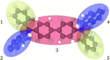 |
| | Fig. 1 Pictorial view of the fully atomistic structure of α-NPD superimposed on the coarse-grained representation. The colour code for atoms is: grey/carbon, white/hydrogen and blue/nitrogen; for the transparent ellipsoids: orange/biphenyl and nitrogen atoms, yellow/phenyl and blue/naphthalene. The beads are indexed from 1 to 5. | |
A CG molecule consists of a properly connected set of these biaxial beads, each endowed with a realistic set of partial charges inside the bead, where the flexibility is retained by allowing the beads to rotate or more generally perform some kind of intramolecular motion. As the atomistic positions inside each bead are known, we also have the possibility of back mapping such a coarse grained configuration to an atomistic one as needed, by e.g. calculation of charge transport properties.
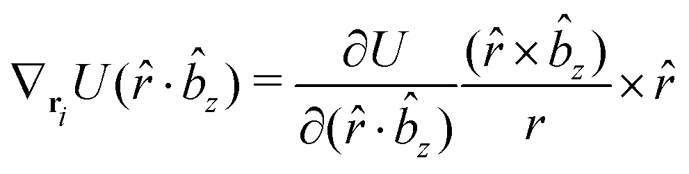
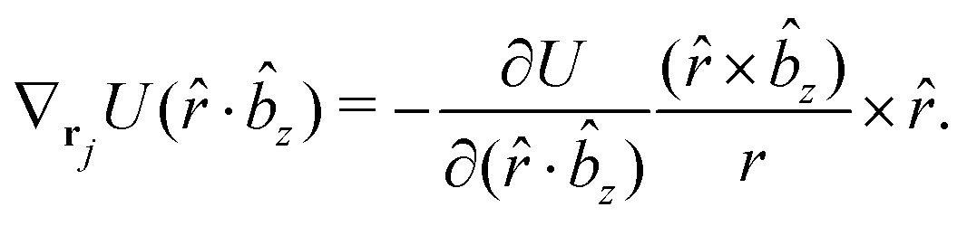
Furthermore, pairs of connected ellipsoids shall interact with a two-body potential which depends simultaneously on the distance and orientations of the connected pair. In this way, the non-bonded interactions for a pair of connected ellipsoids can be safely excluded, as commonly done in atomistic force fields.
A novel feature of this approach improving its efficiency is to use the information regarding the orientation of the ellipsoids to derive the position in space of the point charges required to model long range electrostatic interactions. The orientation is also used by a two-body potential to constrain the motion of bonded ellipsoids, thus removing the need to define three- and four-body interaction terms, as in other CG models.
In the next sections we develop the coarse grain methodology and its implementation and apply the proposed procedure for the modelling of the hole transporter molecule N4,N4′-di(naphthalen-1-yl)-N4,N4′-diphenyl-[1,1′-biphenyl]-4,4′-diamine (α-NPD) and its molecular organization. We compare the results of the CG simulations with independent atomistic MD trajectories. Furthermore, we demonstrate that it is possible to map the fully atomistic structure into the CG model, achieving a consistent level of description between the two representations.
2 Methodology
In the proposed CG procedure, we introduce anisotropic beads, each representing a suitably chosen group of rigidly connected atoms with a single biaxial ellipsoid.41,42 As already mentioned, this choice is motivated by the need to describe in particular organic semiconductors, a class of materials often characterized by large π conjugated systems. These moieties have a prototypical shape often resembling an oblate ellipsoid, with different axes σx, σy, and σz, more than a uniaxial one with σ⊥ and σ‖, or a spherical one with diameter σ, to which they can anyway be reduced if needed. Large molecules are partitioned into several of these biaxial fragments, typically connected by sigma bonds in the underlying all-atom (AA) representation. For example, in the case of the common hole transporter α-NPD, the molecule can be divided into five fragments, as shown in Fig. 1. The choice of how to partition the molecule in beads is fairly empirical, although based on chemical knowledge and, if needed, on preliminary quantum chemical calculations to identify relatively rigid conjugated fragments interconnected by single bonds.
We have chosen the biaxial Gay–Berne (GB) potential41,42 to describe the short-range repulsive and attractive interactions between the ellipsoidal beads. Point charges are also added to each bead to account for the electrostatic interactions. Together, the Coulomb and Gay–Berne potentials account for all the non-bonded interactions. Each pair of directly connected ellipsoidal beads interacts instead only via a “bonded” potential, in the sense that the standard non-bonded interactions are not computed for the bonded pair. In this approach we also allow the connected ellipsoids to overlap to some extent in space, if needed, thus providing an accurate representation of the excluded volume of the whole molecule, which in turn is quite important to reproduce realistic mass densities.
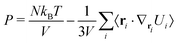
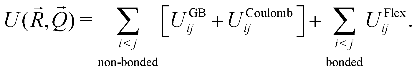
The overall internal energy of the CG system can then be written as the sum of three terms:
| |  | (1) |
The internal energy depends upon the set of positions ![[R with combining right harpoon above (vector)]](https://www.rsc.org/images/entities/i_char_0052_20d1.gif) = {r1,r2,…,rn} and orientations of all the beads in the system, with the orientations being expressed as a quaternion set,
= {r1,r2,…,rn} and orientations of all the beads in the system, with the orientations being expressed as a quaternion set, ![[Q with combining right harpoon above (vector)]](https://www.rsc.org/images/entities/i_char_0051_20d1.gif) = {q1,q2,…,qn}. The Gay–Berne energy UGB is an attractive–repulsive interaction for two rigid biaxial GB ellipsoids, developed by our group41–43 to extend the classical GB potential for cylindrically symmetric ellipsoids33 to fully biaxial ones. The length, width and thickness, but also the strength of interaction of the ellipsoid along its three principal axes, can assume different values,41,42,44 providing a reasonable representation of real molecular fragments. More explicitly, the GB biaxial potential is given by the following equation:41,42,45
= {q1,q2,…,qn}. The Gay–Berne energy UGB is an attractive–repulsive interaction for two rigid biaxial GB ellipsoids, developed by our group41–43 to extend the classical GB potential for cylindrically symmetric ellipsoids33 to fully biaxial ones. The length, width and thickness, but also the strength of interaction of the ellipsoid along its three principal axes, can assume different values,41,42,44 providing a reasonable representation of real molecular fragments. More explicitly, the GB biaxial potential is given by the following equation:41,42,45
| | UGBij = 4ε0ε(![[r with combining circumflex]](https://www.rsc.org/images/entities/i_char_0072_0302.gif) ij,qi,qj)[u12(rij,qi,qj) − u6(rij,qi,qj)], ij,qi,qj)[u12(rij,qi,qj) − u6(rij,qi,qj)], | (2) |
where
rij ≡
ri −
rj is the inter-particle vector connecting the centres of mass of the two interacting GB beads, with modulus distance
rij, and direction along the unit vector
ij, while
ε0 defines the energy scale. The orientations,
qi and
qj, of the two ellipsoids, classically given in terms of three Euler angles,
46 are here represented by four-component quaternions (
qi).
47,48 This last approach has been chosen to avoid spurious numerical divergence problems in the integration of the rotational equations of motion.
31,48–50 To solve the equations of motion a standard velocity Verlet algorithm
31 has been applied, taking into account also orientational degrees of freedom, for both atomistic and coarse-grained models.
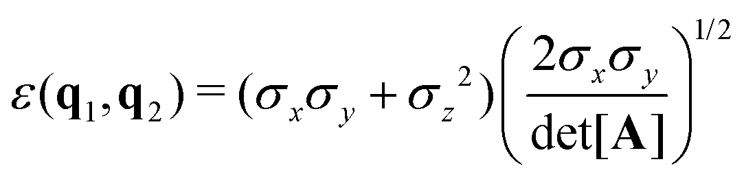
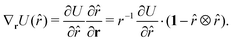
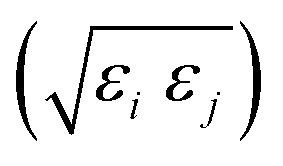
The function u(rij,qi,qj) = σc/(rij − σ(![[r with combining circumflex]](https://www.rsc.org/images/entities/b_char_0072_0302.gif) ij,qi,qj) + σc) contains the anisotropic contact term σ(ij,qi,qj), which approximates the geometrical “contact distance” between the two ellipsoids and depends on their axis lengths σx, σy and σz, plus the term σc, controlling the width of the potential well. The attractive interaction term ε(ij,qi,qj) defining the potential well depth depends on the orientations of the two particles and of the inter-bead vector as well as on the interaction parameters εx, εy and εz. Explicit expressions are given in Appendix B. This last set of parameters is directly related to the well depths for two GB particles approaching with fixed parallel orientations along the three Cartesian directions. Each type of ellipsoid corresponds to a chemical moiety and is parametrized with a single set of σ and ε values. When ellipsoids of two different types come close enough to interact, Lorentz–Berthelot mixing rules31 are applied, as commonly used for our type of bottom up modelling: the arithmetic average is used for combining shape information, ((σi + σj)/2), while interactions are calculated by means of geometric averages
ij,qi,qj) + σc) contains the anisotropic contact term σ(ij,qi,qj), which approximates the geometrical “contact distance” between the two ellipsoids and depends on their axis lengths σx, σy and σz, plus the term σc, controlling the width of the potential well. The attractive interaction term ε(ij,qi,qj) defining the potential well depth depends on the orientations of the two particles and of the inter-bead vector as well as on the interaction parameters εx, εy and εz. Explicit expressions are given in Appendix B. This last set of parameters is directly related to the well depths for two GB particles approaching with fixed parallel orientations along the three Cartesian directions. Each type of ellipsoid corresponds to a chemical moiety and is parametrized with a single set of σ and ε values. When ellipsoids of two different types come close enough to interact, Lorentz–Berthelot mixing rules31 are applied, as commonly used for our type of bottom up modelling: the arithmetic average is used for combining shape information, ((σi + σj)/2), while interactions are calculated by means of geometric averages  . The number of parameters is necessarily fairly high but the parametrization procedure has to be performed only once per type of molecule and the protocol to obtain the size and interaction strength parameters is well defined, as we shall discuss later on.
2.1 Off-centre charges
Electrostatic interactions are essential to get a realistic prediction of phase behaviour, as demonstrated by various studies in which they have been omitted on purpose. For instance, in a simulation study of the common smectogen liquid crystal 4-cyano-4′-n-octyl-biphenyl (8CB) and its phase diagram, a shift of some 80 degrees of the nematic–isotropic transition temperature was observed when omitting electrostatic interactions.51 The transition temperature for the same liquid crystal with full electrostatic interactions included (and admittedly some other minor changes to the FF) can be found within 3 degrees of experiment.52 In a classical atomistic model for large, neutral, organic molecules, and in the ensuing simulations, electrostatic interactions are typically calculated by using non-polarizable force fields, i.e. estimating first the partial charge on every atom from QC calculations at some level of theory and assuming that these are fairly constant, at least for the range of temperatures and densities explored.
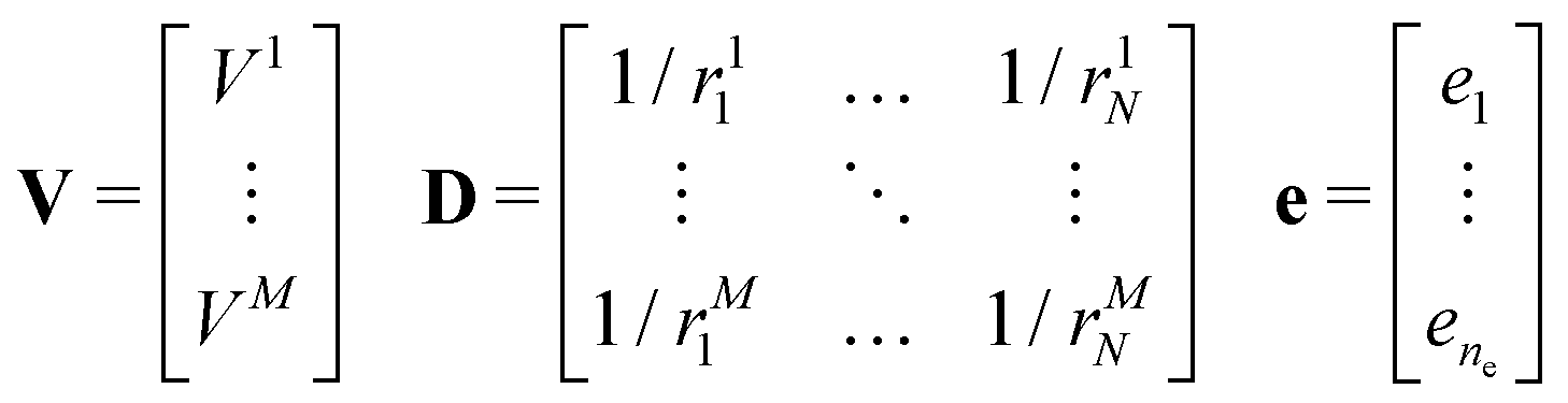
In the proposed CG model, the electrostatic interactions are included in the model through a “small” set of ne point charges ei, placed inside the ellipsoidal beads, whose position and intensity are determined so as to reproduce within a certain error threshold the electrostatic potential corresponding to the full set of partial charges residing at the atomic positions.
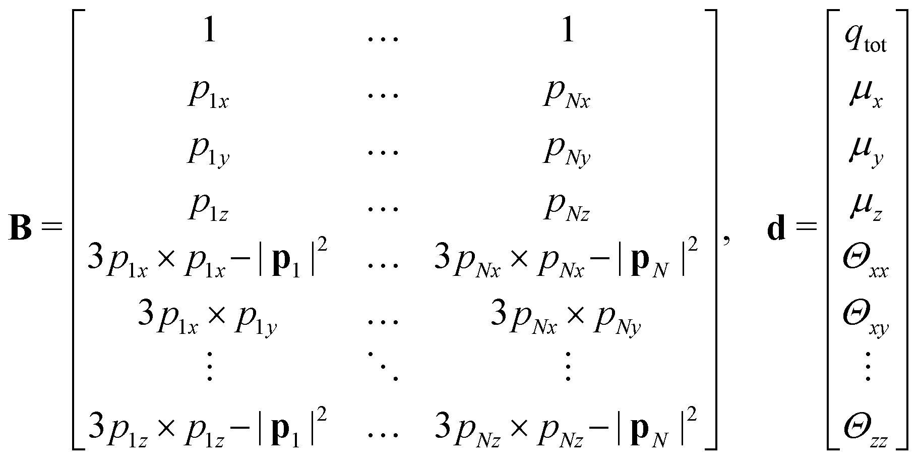
The molecular electrostatic potential is evaluated at a set of points pi outside the bead.7 New charges ei were fitted independently for each bead. An initial guess of the charges, non equivalent under the symmetry operations of the molecular fragment, is placed inside the bead within a skin distance from the surface. The optimal position of each charge is obtained through a genetic algorithm along the lines described in ref. 7. The original approach has been improved by imposing constraints such as maintaining the total charge of the fragment, and optionally by reproducing the quadrupole and the dipole of the underlying molecular fragment, if non vanishing. The charges ei are obtained by solving a linear least squares problem, i.e. the minimization of ‖V − De‖2 subject to linear equality constraints Be = d, as implemented in the LAPACK53 routine DGGLSE,
where
Vi is the molecular electrostatic potential at points
pi due to the atomic charges in the fragment;
rij is the distance between atom
j and point
pi; and
ei is the new set of reduced charges to be determined. The constraints are:
where
pij is the
j-th component of the
i-th atomic position in the particle frame with origin at the centre of mass of the ellipsoidal bead which coincides with that of the atomistic fragment, and
μi is the
i-th component of the molecular dipole moment of the fragment. Every line in the
B matrix corresponds to a linear constraint: the first line accounts for the total charge
qtot of the bead; the following three lines account for the molecular dipole; and the last nine lines account for the molecular quadrupole
Θij. The condition of the sum of reduced charges matching the total charge
qtot can always be enforced. Conversely, the additional constraints can be dropped, depending on the chosen number of reduced charges. Since the charges are, in general, not placed in the centre of the bead, we refer henceforth to this treatment of electrostatics as OCC (off-centre charges).
Electrostatic interactions due to the OCC charges are decomposed into the direct (Coulomb) pairwise summation and into the long-range reciprocal space parts, with the so called particle–particle and particle–mesh (PPPM) method.54 Since the ne charges are rigidly connected to their embedding bead, they produce also inter-bead forces and torques on the bead. Their analytical expressions have been implemented in the LAMMPS molecular dynamics program,55,56 for both the direct Coulomb summation and the PPPM long range parts of the potential.
As an implementation note, the OCC charges are defined in the molecular frame of the bead they refer to. The positions of OCC charges are not explicitly kept track of during the integration of the equations of motion. When the actual coordinates are needed for evaluating the electrostatic interactions, their position is derived from the actual state of the bead in the laboratory frame. In this way, a significant saving is achieved in terms of computer memory savings, the reason being the use of a shared neighbour list with the GB interactions.
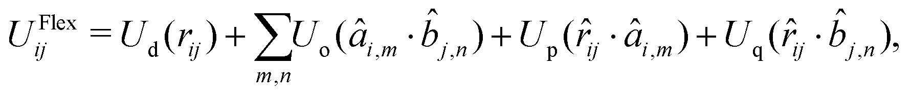
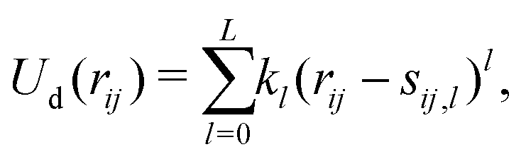
2.2 Bonded potential between ellipsoids
The potential UFlex in eqn (1) depends on (and therefore controls) the distance and relative orientation between a pair of bonded ellipsoids. The non-bonded interaction terms are switched off for every pair of bonded ellipsoids, but they are computed without any scaling factor for 1–3- and 1–4-connected ellipsoids, for which the positions and orientations are not directly correlated.
The pair potential UFlexij between beads i and j is written in the form57
| | UFlexij = U(rij, {âi,m·ij}, {![[b with combining circumflex]](https://www.rsc.org/images/entities/i_char_0062_0302.gif) j,n·ij}, {âi,m·j,n}). j,n·ij}, {âi,m·j,n}). | (3) |
Eqn (3) depends on all the possible scalar products of the unit vectors ij, âi,m and j,n, plus the scalar distance rij. The orientation of particles i and j is described with the unit vectors âi,m and j,n, where the indexes m, n = x, y, z correspond to the Cartesian axes of each ellipsoid, and ij is the direction of the bond.
Since the scalar products are invariant to a global rotation of coordinates, the forces and torques derived from a potential with the general form of eqn (3) guarantee the conservation of the local angular momentum.57 Many potentials have been presented in the literature for the simulation of granular solids composed of rigid bodies connected with bonds.58 The general form of the pair potential used in this work is:
| |  | (4) |
where the sum runs over all the unit vectors
âm,
n. The first term depends on the scalar distance
rij and is parametrized with a simple polynomial expansion, truncated at rank
L:
| |  | (5) |
where
kl is a force constant and
sij,l the offset. The term
Uo controls the relative orientation of the two beads and, in general, depends on any of the 9 possible scalar products
âm·
n, with
m,
n ∈ {
x,
y,
z}. In practice, only 3 terms need to be parametrized, as far as each of the unit vectors
âm and
n is included only once. The analytical expression of
Uo depends on the shape of the empirical potential and can take the form of
eqn (5) or of a cosine series:
| |  | (6) |
where
kl is the Fourier coefficient and
sij,l the phase factor for order
l.
Eqn (6) is used when the empirical potential is defined in the domain [−1, 1], meaning that the scalar product describes a relative rotation of the bonded pair.
The third and fourth terms, Up and Uq, control the position and orientation of the beads relative to the bond ij. The analytical expression of this term is a polynomial expansion analogous to eqn (5).
2.3 Parametrization
The parametrization of the MOLC model is obtained with a bottom-up approach, starting from the atomistic representation of the single molecule.
For the specific case of organic semiconductors, the full atomistic force field was obtained from the online repository advanced topology builder (ATB), version 2.2.59–61 The ATB force field is based on GROMOS version 54A7, a united-atom non-polarizable force field originally developed for the simulation of biomolecular systems.62,63 In the GROMOS-ATB force field, explicit hydrogen atoms are included in the level of description. The planarity of aromatic rings is ensured by harmonic potentials acting on improper dihedral angles. In addition, the third or 1–4 covalently bound neighbour atoms that are part of aromatic rings are excluded from the non-bonded interactions64 by defining a dummy (aka exclusion) bond connecting these atoms.
Minor changes were made to the molecular topology obtained from the ATB repository: namely, the exclusion bonds were removed between aromatic moieties connected by single bonds, e.g. in tertiary amines and in the biphenyl group.61,64 The amended GROMOS-ATB force field was used in conjunction with the program MOLTEMPLATE65,66 to generate the input files required to carry out the MD simulations at the atomistic level of detail. Since the completion of this work, the ATB repository has been upgraded and the proposed corrections implemented in version 3.0.
The first and most important step to build the CG representation is the partitioning of a large molecule into fragments, which will be represented as three-dimensional ellipsoids. Typically, the molecular fragments should be rigid enough to be safely described by a single ellipsoidal bead, and they should be connected by sigma bonds to the other fragments.
In the MOLC energy expression eqn (1), the bonded (UFlexij) and non-bonded (UGay–Berneij + UCoulombij) interactions are mutually exclusive: only one of them is active for any given pair of beads, analogously to what is commonly done in atomistic force fields. However, defining the connectivity in the CG representation is not equally trivial. In the specific case of α-NPD (Fig. 1), the beads 1, 2 and 3, plus the beads 3, 4 and 5, are connected in a tertiary aniline, and the resulting connectivity of the CG model is summarized in Table 1.
Table 1 Summary of the energy terms acting between beads in the MOLC model of α-NPD: “B” stands for bonded (Flex) interactions; “N” stands for non-bonded (Gay–Berne & Coulomb) interactions. The beads are numbered as in Fig. 1
|
|
1 |
2 |
3 |
4 |
5 |
| 1 |
|
B |
B |
N |
N |
| 2 |
|
|
B |
N |
N |
| 3 |
|
|
|
B |
B |
| 4 |
|
|
|
|
B |
| 5 |
|
|
|
|
|
Analogously to the atomistic model, the naphthyl (beads 2 and 4) and phenyl (1 and 5) fragments are connected to the central biphenyl fragment (3), the latter including also the two nitrogen atoms. In contrast with the atomistic model, the MOLC model includes also two additional bonding terms between the naphthyl and phenyl fragments on the same side of the α-NPD molecule.
The rationale behind this choice is that if two beads exhibit correlated motions, non-bonded interactions alone are not able to reproduce correctly the molecular motions, which will be otherwise dominated by the symmetry of the GB potential and by the OCC electrostatics. The bonded potential, on the other hand, is designed to assign different energetic contributions to the scalar products ξ, hence its ability to describe the motions of correlated beads.
The bonded potential is computed from an atomistic MD simulation of a single molecule in the gas phase at constant volume (NVT conditions), carried out for at least 120 ns in order to sample adequately the configurational space. Afterwards, the atomistic MD trajectory is mapped into the CG representation and the scalar products ξ listed in eqn (9) are computed for every pair of beads in the molecule. This raw information is post-processed into histograms for each degree of freedom ξi, with the condition that chemically equivalent beads are combined into a single histogram, yielding a homogeneous description of symmetric fragments which, for the specific case of α-NPD, corresponds to the naphthyl and phenyl fragments. Finally, the probability distribution histograms p(ξi) are converted into effective potentials by Boltzmann inversion, as follows:
| | Ueff(ξi) = −kBT![[thin space (1/6-em)]](https://www.rsc.org/images/entities/char_2009.gif) ln[p(ξi)]. ln[p(ξi)]. | (7) |
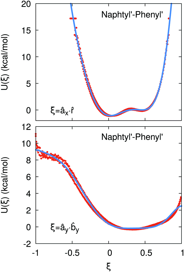
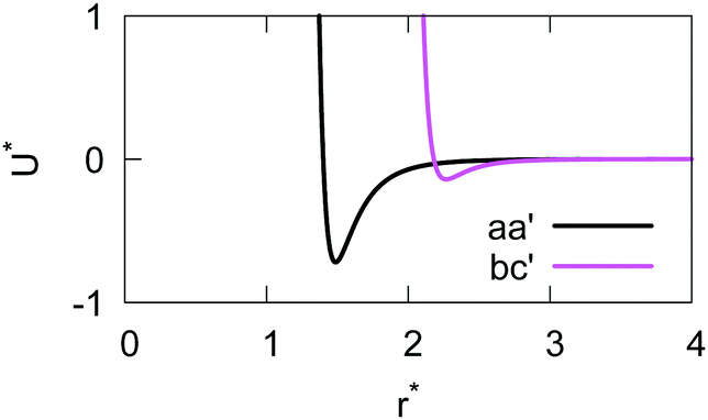
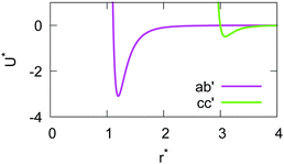
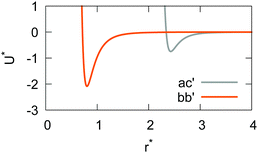
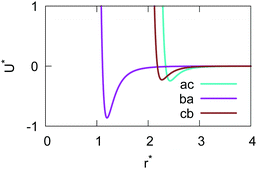
If the resulting potentials do not vary by more than kBT (i.e. ≈0.6 kcal mol−1 at 300 K), the pair of ellipsoids is considered uncorrelated and, as a consequence, they will interact only with the non-bonded terms. An example of correlated potentials is those defined between the naphthyl and phenyl fragments on the same side of the α-NPD molecule (Fig. 2), while uncorrelated potentials are those defined between the naphthyl and phenyl fragments on the opposite side of the molecule (Fig. 3).
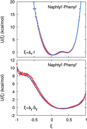 |
| | Fig. 2 Example of correlated potentials between the naphthyl and phenyl fragments on the same side of the α-NPD molecule. The scalar products shown are âx· (top) and ây·y (bottom). The blue curves represent the fitted potentials. | |
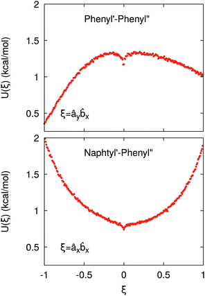 |
| | Fig. 3 Example of uncorrelated potentials between the phenyl fragments (top) and the naphthyl and phenyl fragments (bottom) on the opposite side of the α-NPD molecule. The scalar products shown are ây·x (top) and âx·x (bottom). | |
Although the uncorrelated potentials shown in Fig. 3 are non-zero, we notice that the energy variation is limited to ≈1 kcal mol−1 and that the potential is defined in the whole parameter space [−1:1]. This behaviour indicates that, overall, the motion of the two fragments is not correlated. The symmetry of the uncorrelated potentials reflects the tendency of each fragment to sit in a preferred orientation, which biases the resulting histogram.
The calculation of the GB parameters, i.e. the ellipsoid semi-axes and the anisotropic strengths of interaction, is carried out by fitting the potential energy curves describing the interactions of two identical atomistic fragments. The target interaction energy is computed on the corresponding AA model and it includes only the Lennard-Jones term in the GROMOS-ATB force field. Several interaction curves are computed by causing two identical atomistic fragments to approach along the 12 independent orthogonal configurations.41 The two fragments are placed initially with identical orientation and a first set of 12 interaction potentials is obtained. Then, one fragment is rotated along its symmetry axis (if any) and another set of interaction potentials is obtained. The procedure is iterated until all the listed modes of approach are sampled. Each individual interaction potential is fitted with a shifted 12-6 Lennard-Jones expression, yielding a set of σ0 and ε0 values. The arithmetic and the geometric average are respectively used to obtain the mean values ![[small sigma, Greek, macron]](https://www.rsc.org/images/entities/i_char_e0d2.gif) and
and ![[small epsilon, Greek, macron]](https://www.rsc.org/images/entities/i_char_e0c6.gif) .
.
The GB parameters are fitted on the set of averaged curves using the non-linear least-squares Marquardt–Levenberg algorithm.67 More details on how the curves are computed and the fitted parameters are obtained will be given in a separate article.
All the parameters of the MOLC force field are stored in the LAMMPS template data format, which is handled with the MOLTEMPLATE suite of programs.65,66 An additional set of instructions has been implemented in the MOLTEMPLATE program to handle rotations of ellipsoidal objects in space. The resulting code has been thoroughly tested and the modifications have been already included in the latest version of the program.
2.4 Forward and back mapping
A fundamental feature of the MOLC model is that it describes reasonably rigid sections of a molecule as a series of connected ellipsoidal particles, which are held in space at positions and orientations closely matching those of the atomistic model. This means that it is always possible to recover the fully atomistic representation from the CG model, allowing for the calculation of physical observables requiring the knowledge of the atomic positions (e.g. charge transport properties) or providing an excellent initial configuration for subsequent atomistic simulations.
The mapping procedure to obtain the CG model from the AA one is called “forward mapping” and consists of the following steps. First, the position of each ellipsoid is computed as the centre of mass of the set of atoms assigned, as previously described, to this bead. Its orientation is defined by the eigenvectors of the molecular inertia tensor, which are obtained by matrix diagonalization.
By convention, we assign the x axis to the eigenvector with the smallest eigenvalue of the inertia tensor, the y axis to the middle one and the z axis to the maximum. However, for highly symmetric atomistic fragments with two almost degenerate eigenvalues, like e.g. the phenyl fragment, the most similar eigenvectors (typically the x and y axes) constantly flip, based on the instantaneous atomistic configuration. This obviously leads to incoherent orientations, so it is important to check that the axes assigned by diagonalizing the inertia tensor are actually correct. To obviate this problem, we select two reference atoms for each bead, each yielding the maximum projection along a given molecular axis. The reference axes are chosen as those giving, simultaneously, the highest projection of the reference atoms on the computed eigenvectors.
The diagonalization of the inertia tensor gives only the direction of the reference axes, leaving undetermined their sense. Two additional constraints are used to disambiguate the sense of direction of two axes, so as to enforce a right-hand rule compliant frame. In practice, the standard rule is to use two atoms as markers and to compute their projection on the axes of inertia. The direction (i.e. the sign) of each axis is thus given by the bigger value of the projection of the reference atom. This procedure is meant to ensure that, in the case of semi-rigid fragments, the atom with the greatest projection along an axis has the smallest probability of giving an inconsistent direction as the molecular conformation is deformed, e.g. during a MD simulation. The use of two reference atoms can be also useful for enforcing a consistent direction on axes of equivalent fragments, like those connected to form a polymer chain, allowing one to use a consistent set of parameters for the bonded terms in the force field.
The inverse procedure of mapping back the atomistic structure on the CG model consists of applying the rotation defined by the quaternion of each bead to its corresponding atomistic representation. Then, the AA fragment is translated so that its centre of mass coincides with the centre of the corresponding ellipsoid.
3 Results and discussion
Two samples containing 1000 molecules of α-NPD have been investigated by means of MD simulations. In one sample the molecules are described at the AA level of detail (78 atoms each), while in the other one they are described with the MOLC model, which consists of five ellipsoidal beads per molecule.
The MD simulations of both models were carried out with a modified version of the LAMMPS molecular dynamics program,55,56 based on the stable release dated 11 August 2017.
The AA sample was simulated in a cubic box with 3D periodic boundary conditions (PBC). A timestep of 2 fs was used to integrate the equations of motion. The pressure and temperature were controlled using a Nosé–Hoover barostat with damping parameters of 0.2 and 2 ps for the temperature and pressure, respectively. The intra- and inter-molecular interactions were described with the GROMOS-ATB force field.59–61
The CG sample was simulated in a cubic box with 3D PBC with a timestep of 10 fs and damping parameters of 1 and 10 ps for the temperature and pressure, respectively. The pressure was controlled with a Nosé–Hoover barostat, while the temperature was maintained with a in-house modified version of the Berendsen thermostat available in LAMMPS, already validated in our previous work (see, e.g.ref. 68 and 69), so as to allow simultaneous scaling of the translational and rotational velocities. Even though the Berendsen thermostat has known limitations as it does not reproduce canonical ensemble fluctuations, it still properly gives the average values needed for the structural properties of interest here and, differently from others, has the essential feature of being very robust during velocity scaling.70 The CG representation is based on the MOLC model. The parameters of the MOLC model were fitted on the corresponding GROMOS-ATB model, as described in Section 2.3. The force field definitions for the AA and CG models were stored in the LAMMPS template data format.
The AA and CG samples were obtained independently from one another, but using the same preparation protocol. Briefly, a cubic lattice with a density of 0.12 g cm−3 was first equilibrated at 300 K and a fixed volume. Then, the sample was shrunk at a fixed rate to a density of ∼1 g cm−3 while the temperature was raised to 500 K, followed by thermal annealing for 10 ns at constant pressure. The sample was then cooled to 300 K at a rate of 0.1 K ps−1. A final run of 10 ns was carried out at 300 K and 1 atm for production and data analysis. The input files for the MD simulations were generated using the program MOLTEMPLATE.65,66 These files are available for download and testing as ESI.†
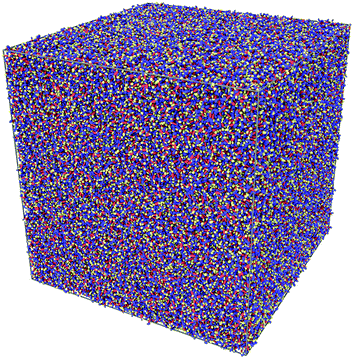
At first glance, the two samples of α-NPD look very similar (Fig. 4). In both cases, the semiconductor forms an amorphous solid with comparable densities: 1.080(1) g cm−3 for the AA sample and 1.205(2) g cm−3 for the CG sample.
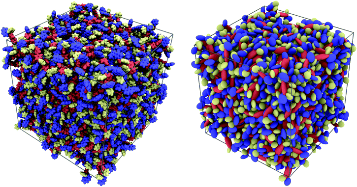 |
| | Fig. 4 Pictorial view of two samples of 1000 α-NPD molecules simulated at T = 300 K and P = 1 atm: all-atom model (left) and MOLC model (right). The molecular fragments are colour-coded as in Fig. 1: biphenyl/orange; naphthyl/blue; and phenyl/yellow. | |
A third sample of α-NPD was obtained by back-mapping the CG sample to its full atomistic representation, followed by an AA-MD simulation. After reaching thermal equilibrium at 300 K, the resulting density of this sample was 1.079(1) g cm−3, in agreement with that of the AA sample obtained from condensation of the gas.
These densities are in turn in reasonable (within ∼10%) agreement with the experimental value of 1.203 g cm−3, for the so called “true density” obtained from gas pycnometry71 measurements at 298 K,72 which obtains the material volume as that unavailable to He gas. The determination of the volume of dense molecular samples is one that has received much attention for more than three decades (see, e.g.ref. 73–77) and is clearly a topic beyond the scope of this work. However, an approximate estimate of the “true density” from our atomistic simulated samples using the V3 voxelator code75 and a probing sphere of radius like that of He (0.33 Å) gives a value of 1.21(1) g cm−3 in very good agreement with experiment.
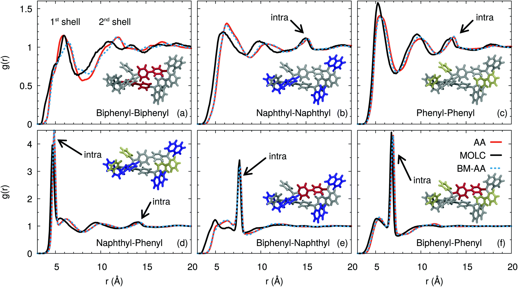
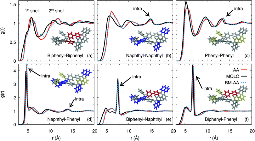
A more quantitative characterization of the amorphous phase of α-NPD is provided by the radial distribution function g(r) computed between the centre-of-mass of the fragments, as defined in Fig. 1. The g(r) functions (Fig. 5) reveal the structural organisation of the amorphous α-NPD samples and allow a direct comparison between the different models.
 |
| | Fig. 5 Comparison between the atomistic and coarse-grained radial distribution functions g(r) computed between the biphenyl (orange), naphthyl (blue) and phenyl (yellow) fragments of the α-NPD molecule, shown as insets. The g(r) functions computed from the AA sample are shown in red, and those from the CG sample in black. The dotted blue curves refer to g(r) functions computed from a sample obtained by back-mapping the CG sample into a new AA one. | |
Very good agreement is obtained between the AA and CG models, both in terms of the shape and intensity of the peaks of the radial distribution functions. In addition, the AA sample obtained by back-mapping (BM-AA) is virtually indistinguishable from the AA one, despite having an independent thermal history. Overall, the morphology of the amorphous phase is consistent between the three samples. The aromatic fragments of the different molecules form a neat shell at a mean distance of ≈6 Å. This distance results from the superposition of T-shaped and offset-stacked pairs, which are the typical interaction geometries for large aromatic rings.78
Despite forming an amorphous solid, the samples of α-NPD display a certain degree of short-range order in the bulk, as shown by the g(r) computed between the biphenyl fragments (Fig. 5(a)). We notice the presence of two coordination shells around each α-NPD molecule, with the first peak being at 5.87 Å for the AA model and 6.25 Å for the CG model. The AA sample shows also a weak third peak at ∼17 Å. This peak is not present in the BM-AA sample, which retains the bulk organisation of its parent CG sample.
The naphthyl–naphthyl and phenyl–phenyl radial distribution functions (Fig. 5(b) and (c)) also display two coordination shells. The first peak between naphthyl fragments is at 6.3 (5.9) Å for the AA (CG) model, while the first peak between phenyl fragments is at 5.6 (5.3) Å for the AA (CG) model. The naphthyl–naphthyl intra-molecular contribution to the g(r) results in a peak at 15.2 (14.2) Å for the AA (CG) model, corresponding to the distance between the two fragments on opposite sides of the same molecule. Analogously, the phenyl–phenyl intra-molecular contribution is found at 13.7 Å for both the AA and CG models.
The radial distribution functions between the naphthyl and phenyl fragments (Fig. 5(d)) show a first sharp peak due to the intra-molecular contribution of the fragments bonded to the same nitrogen atom, and another shallow peak at 14.5 Å due to the fragments on opposite sides of the molecule. The CG model shows a splitting of the first peak, which is not present in the AA and BM-AA models. The first inter-molecular peak is located at 6.2 Å, consistent with the distance obtained for the naphthyl–naphthyl and phenyl–phenyl fragments. The first peak is present in the CG model only as a shoulder, partially hidden by the intra-molecular peaks, while the second one coincides with those in the AA and BM-AA models.
The intra-molecular distance between the biphenyl and naphthyl fragments (Fig. 5(e)) is 7.7 Å and is consistently reproduced by the three models. The first broad peak at around 6.0 (4.8) Å for the AA (CG) model is due to neighbouring molecules in the first coordination shell.
The first intra-molecular peak is less intense compared to that computed between the biphenyl and phenyl fragments (Fig. 5(f)). The likely reason is that the larger size of the naphthyl fragment results in wider oscillations of its centre of mass. Beside, the intra-molecular distance between the biphenyl and phenyl fragments is 6.9 Å. The corresponding peak has a sharp and intense line, due to the localized position of the centre-of-mass of the two moieties.
From this analysis, we conclude that the typical hopping distance in amorphous α-NPD is ≈6 Å.
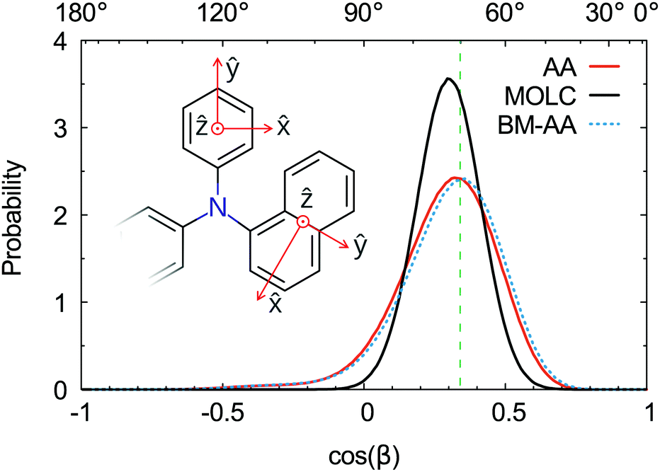
The spatial orientation of the naphthyl and phenyl fragments can be characterized by the tilt angle with respect to the tertiary amine. This angle is defined by the scalar product between the axes perpendicular to the aromatic rings, as shown in the inset of Fig. 6. The typical tilt angle between the planes of aromatic rings is 70°. This reference value was computed at the DFT level of theory for the triphenylamine molecule in the gas phase. The distribution of the tilt angles between the naphthyl and phenyl fragments (Fig. 6) is in good agreement with the reference value. The AA and BM-AA samples have the maximum of the distribution at exactly 70°, while the CG model yields a distribution at a slightly bigger angle of 72.5°.
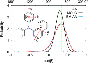 |
| | Fig. 6 Distribution functions of the angle β computed between the axis ẑ of the phenyl and naphthyl residues for amorphous samples of α-NPD: AA model (red), MOLC model (black) and back-mapped AA model (dashed-blue). The dashed green line represents the reference value computed between the phenyl fragments of the molecule triphenylamine. | |
The distribution of the tilt angle between the naphthyl and phenyl fragments reveals that the MOLC model is able to reproduce the rotations of the phenyl and naphthyl groups around the tertiary amine. Furthermore, the BM-AA sample has a distribution of tilt angles nearly identical to that of the reference AA sample, proving that the morphology of the parent CG sample rapidly relaxes to one which has the same characteristics as the reference morphology.
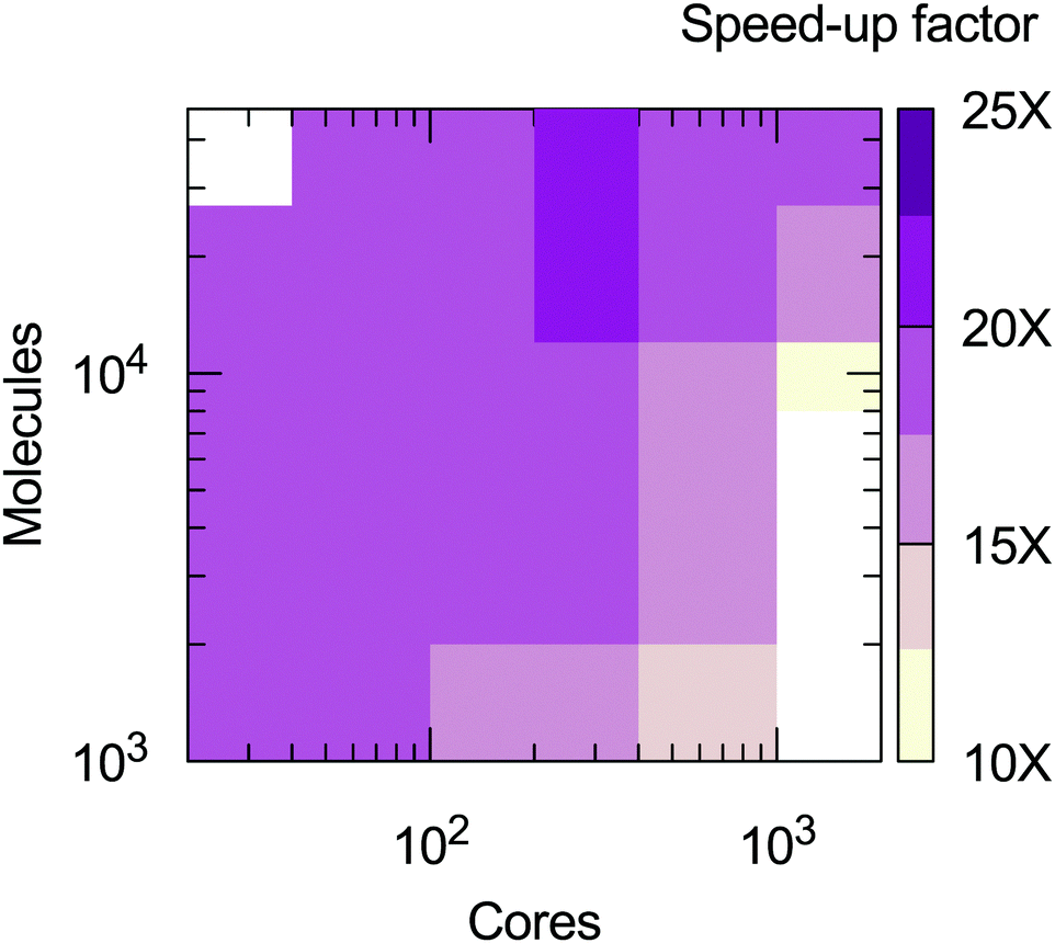
From the calculations presented is possible to evaluate the computational efficiency of the MOLC model with respect to its AA counterpart. The benchmark calculations were run on the ForHLR II cluster at the Karlsruher Institut für Technologie, using 20-way Intel Xeon E5-2660 v3 (Haswell) computing nodes. A radius of 14 Å was used to cut-off the short-range interactions for both the AA and MOLC models. The results (Fig. 7) show that the MOLC model has a decreased computational cost over the AA model, with a maximum speed-up factor of 25 times, measured by the ratio of the production time, in ns per days.
 |
| | Fig. 7 Speed-up factor of the MOLC model over the AA model, measured in terms of production velocity (ns per day). White regions were not sampled. | |
4 Scaling up
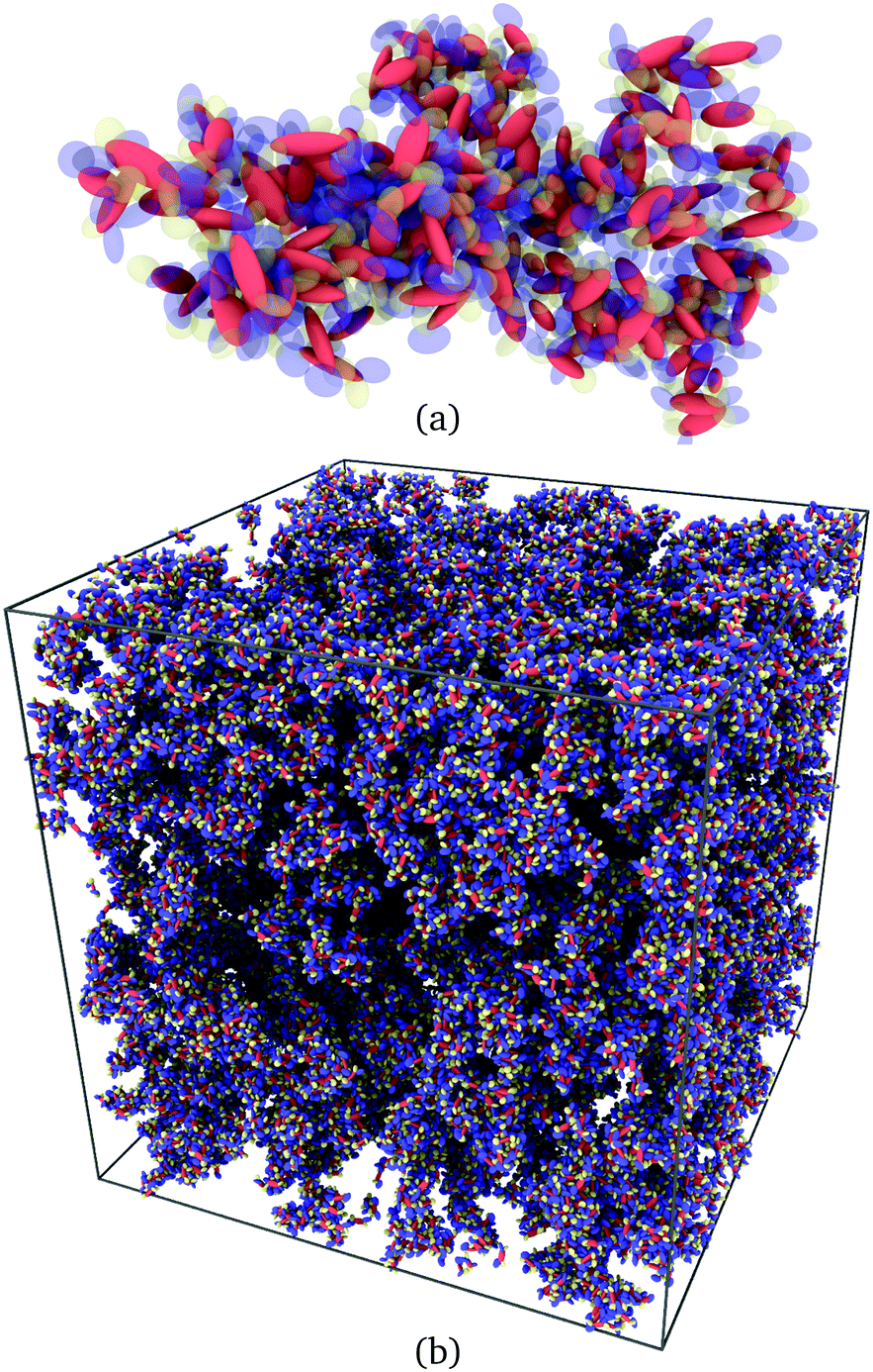
Having satisfactorily checked that the sample of 1000 CG molecules gives results in quantitative agreement with the analogous atomistic one, it remains to be demonstrated that it is possible to scale up the MD simulations for samples of the order of 106 ellipsoids. To do that, we have created a 6 × 6 × 6 supercell of the original CG sample and obtained a large sample containing 216000 CG molecules in a cubic box with an edge length of 55.4 nm. A pictorial view of the sample is given in Fig. 8.
 |
| | Fig. 8 A snapshot of a CG sample in a cubic box with edges of 55 nm. The sample contains 216000 α-NPD molecules, for a total of over 106 ellipsoidal beads. | |
For this sample, the CG MD simulations were performed using a timestep of 20 fs and damping constants of 2 and 20 ps for the temperature and pressure, respectively. The CG sample was first heated to and equilibrated at 600 K until formation of a liquid, monitored by a sharp increase of the RMS displacement of the molecules. The sample was then quenched to 300 K at a rate of 5 K ns−1, and equilibrated for 100 ns. A production run of 20 ns was used for data analysis.
The density and radial distribution functions computed for the large sample are identical to those obtained for a sample of 1000 molecules. However, the larger size of the latter sample provides a better description of the amorphous phase.
For example, in a mesoscopic sample, structural defects and crystal domains are less constrained by the periodicity imposed by the translation vectors. A realistic representation of the condensed phase of an organic semiconductor is then an essential ingredient for the calculation of physical observables such as charge carrier mobility.79
Although the focus of this work is on obtaining large scale, mesoscopic morphologies and molecular organizations rather than charge mobilities, some considerations and an assessment of molecular clustering might be in order, also in view of applications in organic electronics. We recall first that in π-conjugated organic semiconductor materials at room temperature, the mobility mechanism is typically associated with charge hopping and regulated by Marcus theory,80 which gives a rate of electron/hole transfer from a molecule i to a neighbouring molecule j depending critically on the orbital coupling Jij. This in turn has a pronounced dependence on structural parameters, e.g. the spacial separation and the relative orientation of the two molecules or π-conjugated fragments involved in the hopping.81–85 This information can be computed beforehand and used to identify percolation pathways based essentially on geometric criteria. One way to do so is by identifying clusters of molecules in which the inter-molecular distances and orientations match certain threshold values.
Here we have proceeded to extract clusters using an algorithm adapted from previous work from our group.86 Briefly, a pair of molecules is considered part of the same cluster if the contact distance between two beads and the angle between two of their axes satisfy a given set of geometrical criteria. For α-NPD, we chose a contact distance of 1 Å for phenyl and naphthyl pairs, and 2 Å for biphenyl/biphenyl; biphenyl/naphthyl; and biphenyl/phenyl pairs. It should be noted that the contact distance differs from the first peak of the radial distribution functions in Fig. 5, which show the separation between the centres of each bead. In addition to having a certain contact distance, the molecules belonging to the same cluster should have the angle between the z axes of phenyl and naphthyl pairs aligned within ±20°; the angle between the x axes of biphenyl pairs aligned within ±20°; and the angle between the x axis of biphenyl and the z axis of phenyl or naphthyl groups within 90° ± 20° degrees.
A typical view of such a cluster of α-NPD molecules is displayed in Fig. 9(a). A network of all the connected clusters is displayed in Fig. 9(b). The identification of clusters is a practical way to select couples of molecules on which to perform electronic structure calculations. In practice, molecules facing each other with minimum superposition of their aromatic fragments can be excluded from the analysis. Moreover, only a small subset of molecules needs to be back-mapped into the full atomistic representation, leaving the rest of the macroscopic sample out of the analysis.
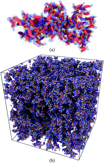 |
| | Fig. 9 (a) Cluster of α-NPD molecules with overlapping fragments and (b) clusters of connected α-NPD molecules forming a percolation network in the mesoscopic sample. | |
Tight geometrical criteria can be used to identify crystal domains and grain boundaries. The cluster analysis revealed that no crystal domain was present in the mesoscopic sample of α-NPD, which retained its amorphous phase after thermal annealing.
5 Conclusions
The task of realistically modelling organic semiconductors, and linking the morphology of the material to its charge-transport properties, is at the central stage of research in the field of organic electronics. Here we have focused on an essential part of the ambitious programme of going from molecular structure to realistic material properties, i.e. the generation of molecular morphologies. To this effect we have introduced a novel coarse-grained modelling approach, MOLC, and its methodology for describing large organic molecules in terms of a set of interconnected and mobile biaxial beads.
By partitioning a large organic molecule into fragments, each represented as a single ellipsoidal bead, the complexity of a molecule is drastically reduced. As the light atoms are effectively removed from the description, so too are the corresponding high-frequency modes which limit the practical possibility of following the time evolution of a large sample in computer simulations. In this way, it is possible to carry out MD simulations accessing timescales and sample sizes not currently possible with all-atom models.
We have shown that the MOLC model correctly represents the excluded volume of a given molecule, its internal degrees of freedom, and the repulsive short-range interactions, as well as the long-range attractive dispersive ones, and the electrostatic interactions. Although several models already exist, the current one presents various novel aspects, as we have discussed. Non-bonded interactions have been modelled using fully biaxial Gay–Berne potentials allowing one to approximate aromatic fragments with a relatively small number of anisotropic units, not too dissimilar from their atomistic counterpart. These beads are in turn decorated with a distribution of point charges to account for the Coulomb interactions. A two-body potential has been developed to control the distance and relative orientation of two connected (bonded) beads. Collectively, these potential energy functions constitute the core of the MOLC model and allow one to simulate in a fairly realistic manner morphologies for samples of size corresponding to tens of nanometres, similar to those used in organic electronic devices. The potential functions have been coded as user-defined modules for the MD code LAMMPS, and made publicly available for testing.
Conflicts of interest
There are no conflicts to declare.
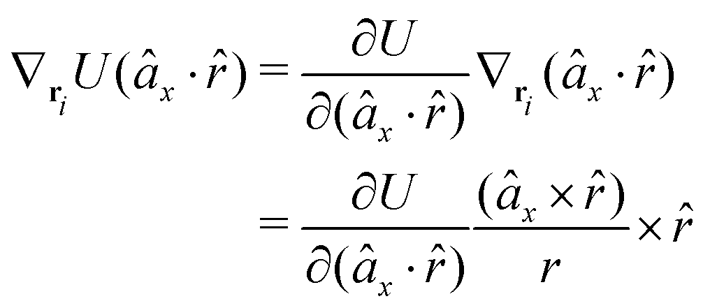
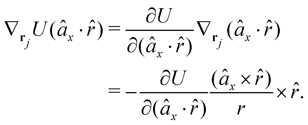
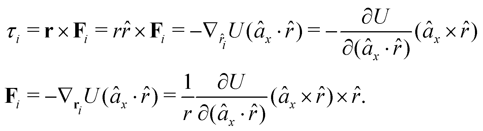
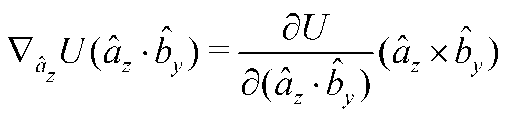
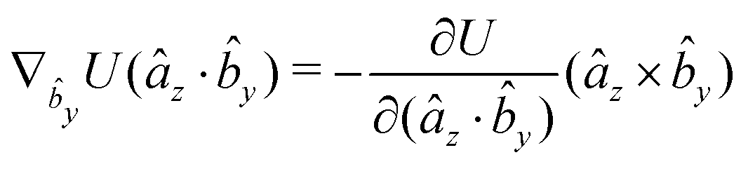
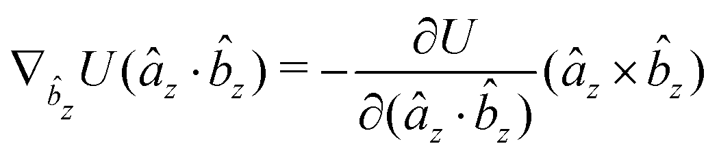
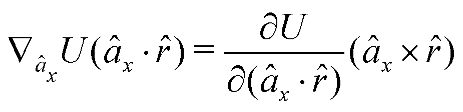
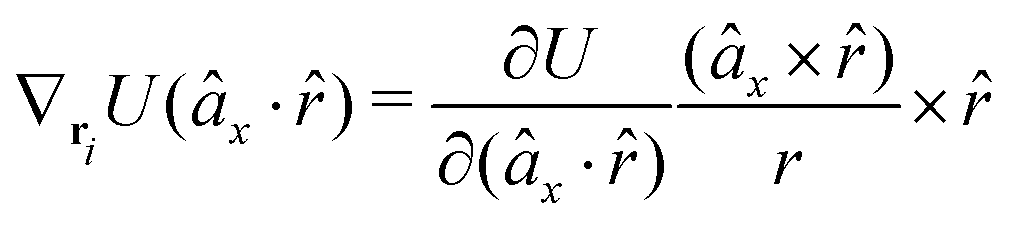
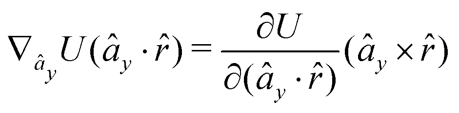
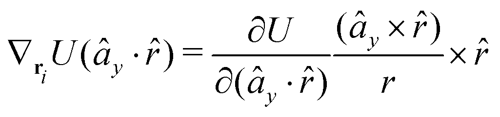
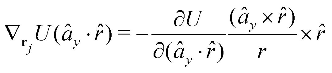
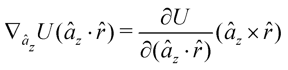
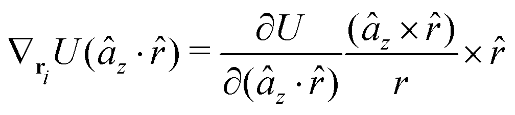
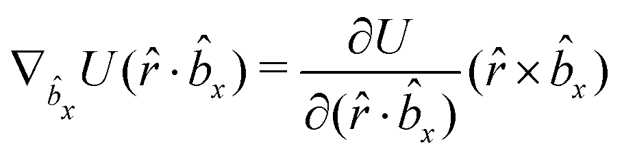
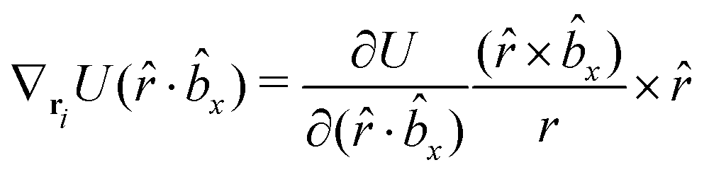
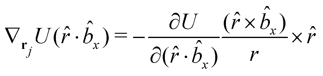
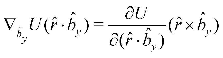
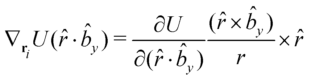
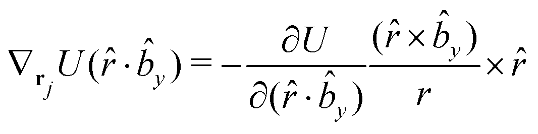
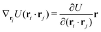
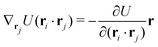
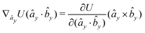
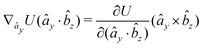
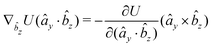
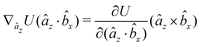
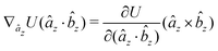
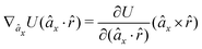
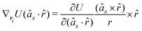
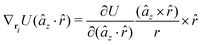
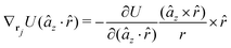
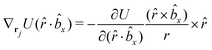
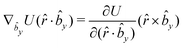
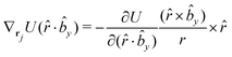
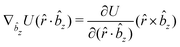
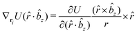
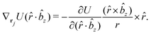
A Analytical expression of forces and torques
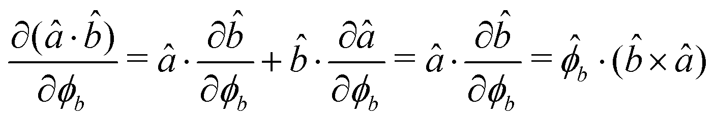
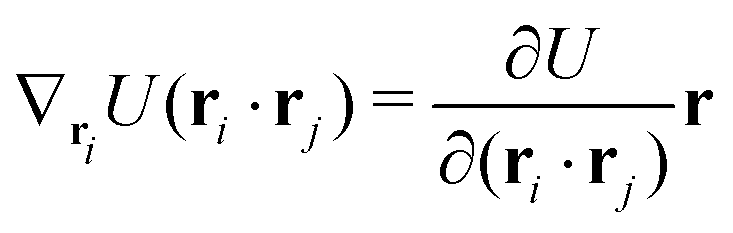
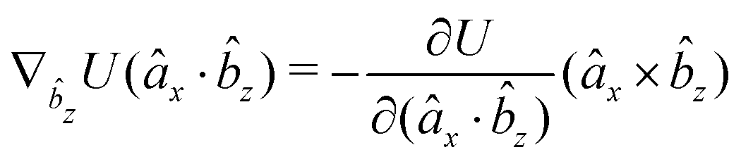
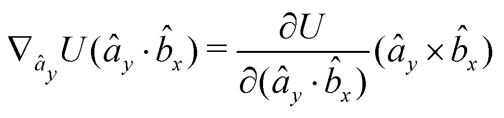
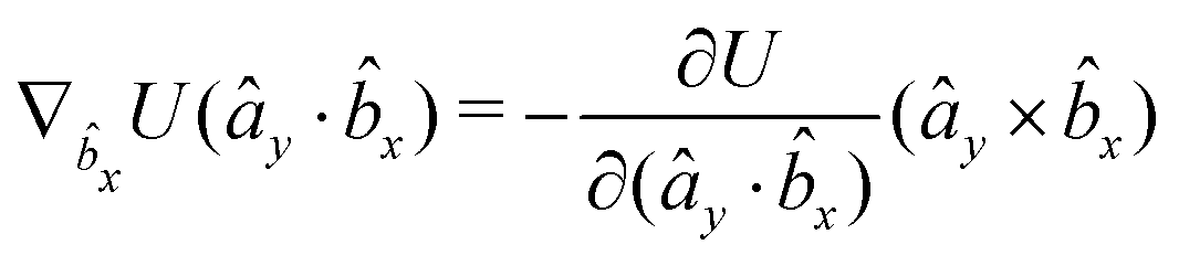
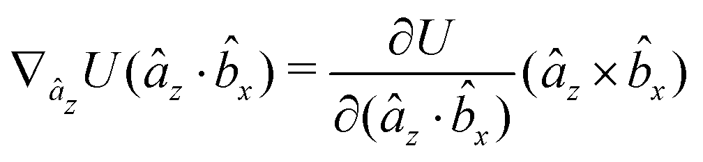
The gradients of the potential UFlex, on which forces and torques depend, are obtained by the chain rule:| | 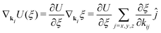 | (8) |
with ki = i for forces; and ki = âx, ây, âz and kj = x, y, z for torques. The variables ξ ∈ ξ are defined as the scalar products:| | | ξ = {âx·x, âx·y, âx·z, ây·x, ây·y, ây·z, âz·x, âz·y, âz·z, âx·, ây·, âz·, ·x, ·y, ·z, r} | (9) |
plus the scalar distance r = ‖rj − ri‖. The unit vector in eqn (9) is defined as = (rj − ri)/r.
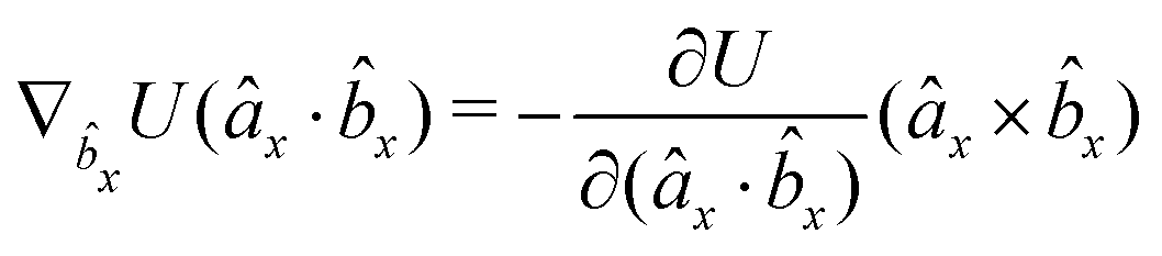
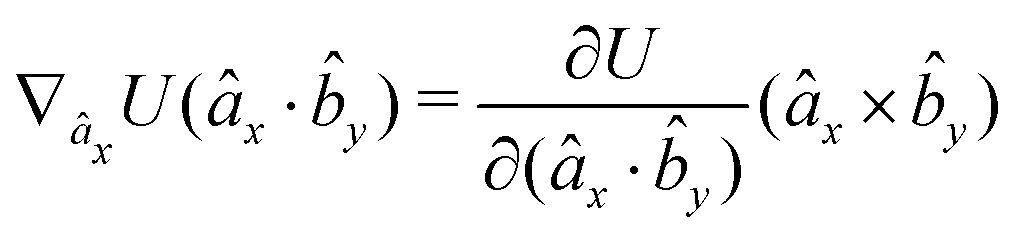
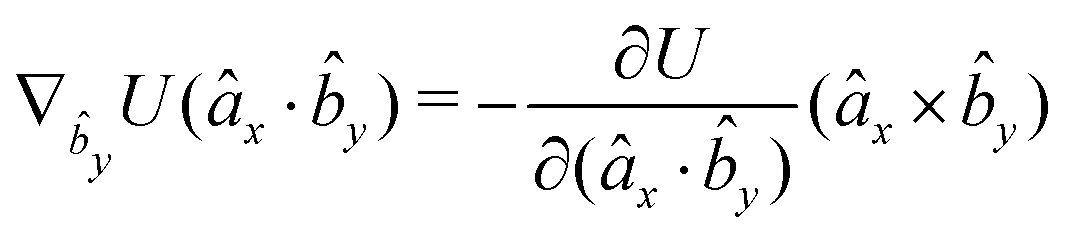
As an example, we derive the vector part of gradients and torques for the term ξ = âx· for particle i. In this case there is a torque acting on both âx and
| | 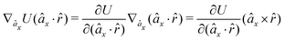 | (10) |
where we used the relations below
| | 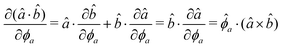 | (11) |
| | 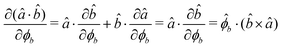 | (12) |
and the torque on
, which means the forces on
ri and
rj,
| | 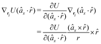 | (13) |
| | 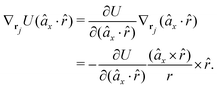 | (14) |
In fact, since a torque is acting on the vector r = rj − ri, it produces a force with a direction perpendicular to that vector and the torque, and inversely proportional to the scalar distance r:
| | 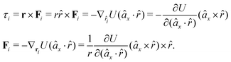 | (15) |
The explicit formulae for gradients and torques on pairs of connected beads due to every ξ term follow:
| |  | (16) |
| |  | (17) |
| |  | (18) |
| |  | (19) |
| |  | (20) |
| |  | (21) |
| |  | (22) |
| |  | (23) |
| |  | (24) |
| |  | (25) |
| |  | (26) |
| |  | (27) |
| |  | (28) |
| |  | (29) |
| |  | (30) |
| |  | (31) |
| |  | (32) |
| |  | (33) |
| |  | (34) |
| |  | (35) |
| |  | (36) |
| |  | (37) |
| |  | (38) |
| |  | (39) |
| |  | (40) |
| |  | (41) |
| |  | (42) |
| |  | (43) |
| |  | (44) |
| |  | (45) |
| |  | (46) |
| |  | (47) |
| |  | (48) |
| |  | (49) |
| |  | (50) |
| |  | (51) |
| |  | (52) |
| |  | (53) |
Only the potential components depending on the inter-particle distance vector contribute to the pressure through the virial equation:
| |  | (54) |
where the summation contains terms depending either on the scalar distance, through
ξ =
r·
r, with
or instead depending on the angular part
i.e. through terms involving
, like
ξ =
·
z,
ξ =
·
âxetc., contributing with
| | | r·∇rU(), | (56) |
where
| |  | (57) |
B Gay–Berne potential
The biaxial GB potential used in this work has been already described elsewhere.41,42,45 Here, we wish to report a handy summary of the equations used to fit the potential energy curves. The anisotropic contact distance is:| | | σ(12,q1,q2) = (2T12A−112)−1/2 | (58) |
and the anisotropic interaction term is written as| | 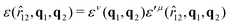 | (59) |
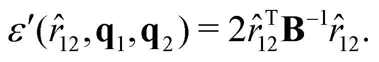
where μ and ν are empirical exponents. The form of the dimensionless strength coefficient ε is:| | 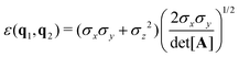 | (60) |
while the expression of ε′ is:| |  | (61) |
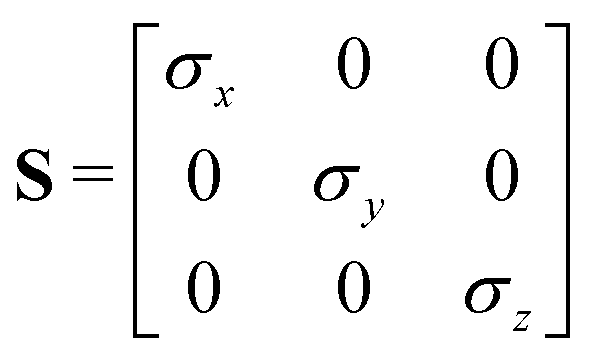
In these equations, the matrices A and B are defined as:| | | A = MT1S2M1 + MT2S2M2 | (62) |
where Mi is the rotation matrix transforming the coordinates from the laboratory to the molecular frame reference, S is a diagonal “shape” matrix:| |  | (64) |
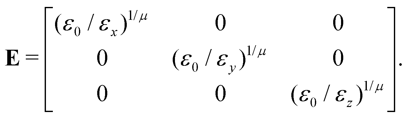
and E is the auxiliary diagonal interaction matrix:| |  | (65) |
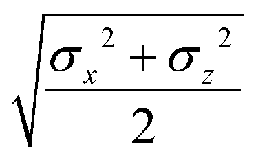
In the previous expressions, the elements σx, σy, and σz are the axes of the ellipsoid representing the molecular fragment, while the coefficients εx, εy and εz are related to the well depths for the side-by-side, width-to-width and end-to-end interactions, and ε0 is the energy scale.
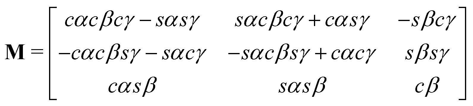
The rotation matrix can be described in terms of the Euler angles:46
| |  | (66) |
where
c stands for cosine and
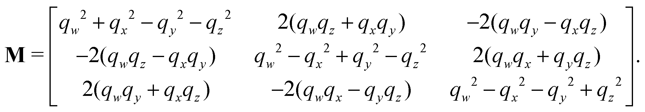
s for sine. Alternatively, the matrix
M can be expressed using quaternions:
| |  | (67) |
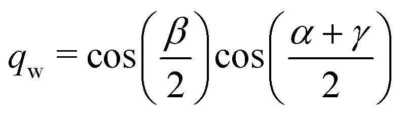
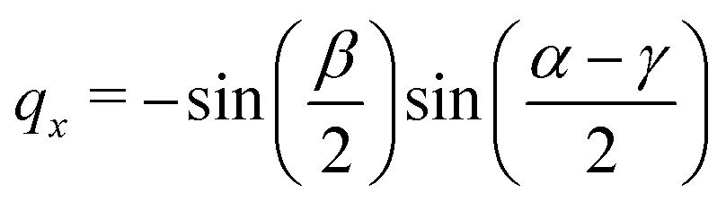
The quaternions are related to the Euler angles through the expressions:
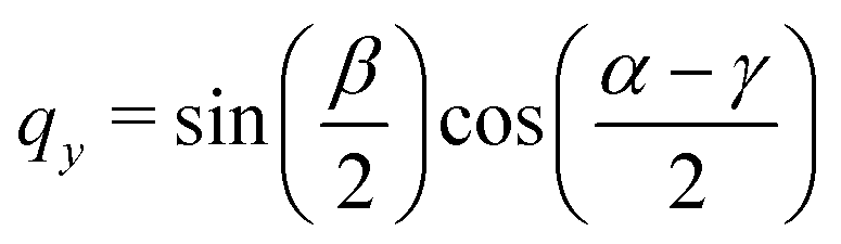
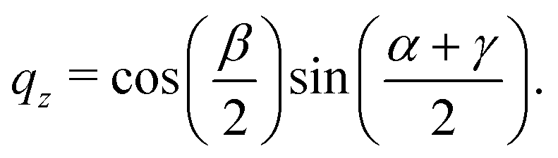
| |  | (68) |
| |  | (69) |
| |  | (70) |
| |  | (71) |
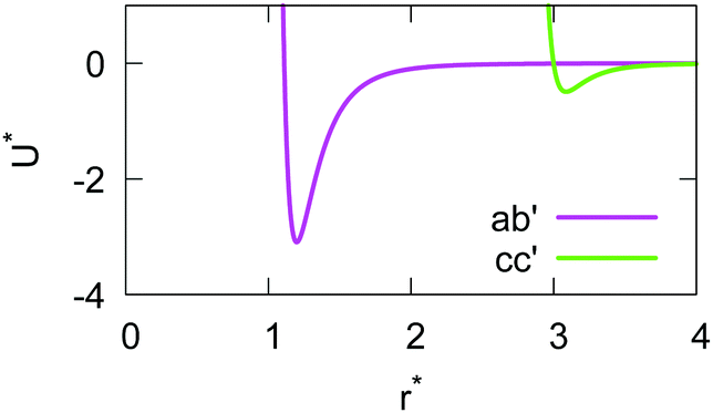
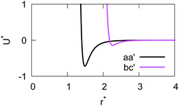
The analytical expressions for the 12 orthogonal modes of approach are reported here to correct some misprinted formulae found in the original ref. 41. Each configuration is obtained by rotating a second molecule (with respect to one which is kept in the same orientation) with a set of Euler angles. The molecule is then displaced along the intermolecular vector r12 parallel to one of the three Cartesian axes. A summary of all the possible modes of approach is reported in Table 2.
Table 2 Name of the 12 orthogonal configurations obtained for rotation ω = {α, β, γ} of a second molecule with respect to the first one and r12 parallel to x1, y1 or z1
|
α
|
β
|
γ
|
r
12‖x1 |
r
12‖y1 |
r
12‖z1 |
| 0 |
0 |
0 |
aa
|
bb
|
cc
|
| 0 |
0 |
π/2 |
ab′ |
(ba′ = ab′) |
cc′ |
| 0 |
π/2 |
0 |
ac′ |
bb′ |
(ca′ = ac′) |
| 0 |
π/2 |
π/2 |
ac
|
ba
|
cb
|
| π/2 |
π/2 |
π/2 |
aa′ |
bc′ |
(bc′ = cb′) |
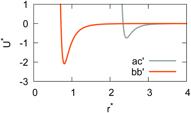
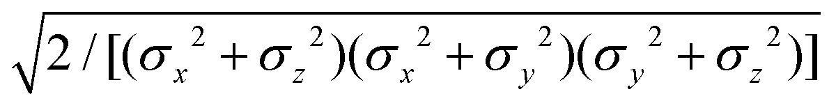
The resulting analytical expressions for the functions σ(r12,q1,q2), ε(q1,q2) and ε′(12,q1,q2) are reported in Tables 3 and 4. A plot for each configuration is also provided, which has been computed using the parameters (σx, σy, σz) = (1.4, 0.714, 3.0), σc = 0.714, (εx, εy, εz) = (1.7,1.0,0.2), μ = 1 and ν = 3.
Table 3 Analytical expressions for the functions σ(r12,q1,q2), ε(q1,q2) and ε′(12,q1,q2) computed for selected configurations
| Configuration |
σ(r12,q1,q2) |
ε(q1,q2) |
ε′(12,q1,q2) |
Plot |
|
aa
|
σ
x
|

|

|
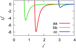
|
|
bb
|
σ
y
|

|

|
|
cc
|
σ
z
|

|

|
|
ab′ |

|

|

|
|
|
cc′ |
σ
z
|

|

|
|
ac′ |

|

|

|
|
|
bb′ |
σ
y
|

|

|
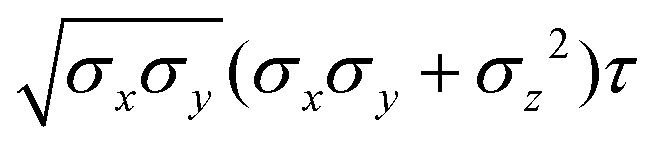
Table 4 Analytical expressions for the functions σ(r12,q1,q2), ε(q1,q2) and ε′(12,q1,q2) computed for selected configurations. The symbol τ is shorthand for 
| Configuration |
σ(r12,q1,q2) |
ε(q1,q2) |
ε′(12,q1,q2) |
Plot |
|
ac
|

|

|
|
|
|
ba
|

|

|

|
|
cb
|

|
|
|
|
aa′ |
σ
x
|
|

|
|
|
bc′ |

|

|

|
Acknowledgements
We thank the European Union's Horizon 2020 Framework Programme for support of this work under grant agreement No. 646176 (EXTMOS). Colleagues from the partner laboratories and the coordinator Prof. A. Walker (U. Bath) are thanked for many useful discussions. This work was performed in part on the computational resource ForHLR II funded by the Ministry of Science, Research and the Arts Baden-Württemberg and DFG (“Deutsche Forschungsgemeinschaft”) and we thank in particular Prof. W. Wenzel (KIT) for granting access. We are grateful to Dr A. Jewett for precious help with MOLTEMPLATE. C. Z. would also like to thank the Isaac Newton Institute for Mathematical Sciences, Cambridge, for support and hospitality (under EPSRC Grant Number EP/R014604/1) during the programme “Mathematical Design of New Materials” when work on this paper was completed.
Notes and references
-
The WSPC Reference on Organic Electronics: Organic Semiconductors, ed. J.-L. Brédas and S. R. Marder, World Scientific, Singapore, 2016 Search PubMed.
-
D.-K. Yang and S.-T. Wu, Fundamentals of Liquid Crystal Devices, Wiley, Chichester, 2nd edn, 2014 Search PubMed.
-
O. Roscioni and C. Zannoni, in Unconventional Thin Film Photovoltaics, ed. E. Da Como, F. De Angelis, H. Snaith and A. B. Walker, Royal Society of Chemistry, London, 2016, pp. 391–419 Search PubMed.
-
C. J. Cramer, Essentials of Computational Chemistry. Theories and Models, Wiley, New York, 2004 Search PubMed.
-
F. Jensen, Introduction to Computational Chemistry, John Wiley & Sons, Chichester, UK, 3rd edn, 2017 Search PubMed.
- B. H. Besler, K. M. Merz and P. A. Kollman, J. Comput. Chem., 1990, 11, 431–439 CrossRef CAS.
- R. Berardi, L. Muccioli, S. Orlandi, M. Ricci and C. Zannoni, Chem. Phys. Lett., 2004, 389, 373–378 CrossRef CAS.
-
M. J. Frisch, G. W. Trucks, H. B. Schlegel, G. E. Scuseria, M. A. Robb, J. R. Cheeseman, G. Scalmani, V. Barone, G. A. Petersson, H. Nakatsuji, X. Li, M. Caricato, A. V. Marenich, J. Bloino, B. G. Janesko, R. Gomperts, B. Mennucci, H. P. Hratchian, J. V. Ortiz, A. F. Izmaylov, J. L. Sonnenberg, D. Williams-Young, F. Ding, F. Lipparini, F. Egidi, J. Goings, B. Peng, A. Petrone, T. Henderson, D. Ranasinghe, V. G. Zakrzewski, J. Gao, N. Rega, G. Zheng, W. Liang, M. Hada, M. Ehara, K. Toyota, R. Fukuda, J. Hasegawa, M. Ishida, T. Nakajima, Y. Honda, O. Kitao, H. Nakai, T. Vreven, K. Throssell, J. A. Montgomery Jr., J. E. Peralta, F. Ogliaro, M. J. Bearpark, J. J. Heyd, E. N. Brothers, K. N. Kudin, V. N. Staroverov, T. A. Keith, R. Kobayashi, J. Normand, K. Raghavachari, A. P. Rendell, J. C. Burant, S. S. Iyengar, J. Tomasi, M. Cossi, J. M. Millam, M. Klene, C. Adamo, R. Cammi, J. W. Ochterski, R. L. Martin, K. Morokuma, O. Farkas, J. B. Foresman and D. J. Fox, Gaussian 16, Revision C.01, Gaussian, Inc., Wallingford CT, 2016 Search PubMed.
-
M. S. Gordon and M. W. Schmidt, Theory and applications of computational chemistry, Elsevier, 2005, pp. 1167–1189 Search PubMed.
- G. te Velde, F. M. Bickelhaupt, E. J. Baerends, C. Fonseca Guerra, S. J. A. van Gisbergen, J. G. Snijders and T. Ziegler, J. Comput. Chem., 2001, 22, 931–967 CrossRef CAS.
- K. Lejaeghere, G. Bihlmayer, T. Bjorkman, P. Blaha, S. Blugel, V. Blum, D. Caliste, I. E. Castelli, S. J. Clark, A. Dal Corso, S. de Gironcoli, T. Deutsch, J. K. Dewhurst, I. Di Marco, C. Draxl, M. Dulak, O. Eriksson, J. A. Flores-Livas, K. F. Garrity, L. Genovese, P. Giannozzi, M. Giantomassi, S. Goedecker, X. Gonze, O. Granas, E. K. Gross, A. Gulans, F. Gygi, D. R. Hamann, P. J. Hasnip, N. A. Holzwarth, D. Iusan, D. B. Jochym, F. Jollet, D. Jones, G. Kresse, K. Koepernik, E. Kucukbenli, Y. O. Kvashnin, I. L. Locht, S. Lubeck, M. Marsman, N. Marzari, U. Nitzsche, L. Nordstrom, T. Ozaki, L. Paulatto, C. J. Pickard, W. Poelmans, M. I. Probert, K. Refson, M. Richter, G. M. Rignanese, S. Saha, M. Scheffler, M. Schlipf, K. Schwarz, S. Sharma, F. Tavazza, P. Thunstrom, A. Tkatchenko, M. Torrent, D. Vanderbilt, M. J. van Setten, V. Van Speybroeck, J. M. Wills, J. R. Yates, G. X. Zhang and S. Cottenier, Science, 2016, 351, aad3000 CrossRef PubMed.
- J. Maddox, Nature, 1988, 335, 201 CrossRef.
- S. Plimpton, J. Comput. Phys., 1995, 117, 1–19 CrossRef CAS.
-
M. J. Abraham, D. van der Spoel, E. Lindahl, B. Hess and the GROMACS development team, GROMACS User Manual version 2019, 2019, http://www.gromacs.org Search PubMed.
- J. C. Phillips, R. Braun, W. Wang, J. Gumbart, E. Tajkhorshid, E. Villa, C. Chipot, R. D. Skeel, L. Kale and K. Schulten, J. Comput. Chem., 2005, 26, 1781–1802 CrossRef CAS PubMed.
- S. J. Marrink, H. J. Risselada, S. Yefimov, D. P. Tieleman and A. H. de Vries, J. Phys. Chem. B, 2007, 111, 7812–7824 CrossRef CAS PubMed.
- W. G. Noid, J. W. Chu, G. S. Ayton, V. Krishna, S. Izvekov, G. A. Voth, A. Das and H. C. Andersen, J. Chem. Phys., 2008, 128, 244114 CrossRef CAS PubMed.
- W. G. Noid, P. Liu, Y. Wang, J. W. Chu, G. S. Ayton, S. Izvekov, H. C. Andersen and G. A. Voth, J. Chem. Phys., 2008, 128, 244115 CrossRef CAS PubMed.
- C. Peter, L. Delle Site and K. Kremer, Soft Matter, 2008, 4, 859 RSC.
- C. Peter and K. Kremer, Soft Matter, 2009, 5, 4357–4366 RSC.
- A. Lyubartsev, A. Mirzoev, L. J. Chen and A. Laaksonen, Faraday Discuss., 2010, 144, 43–56 RSC.
- A. R. Smith, I. R. Thompson and A. B. Walker, J. Chem. Phys., 2019, 150, 164115 CrossRef PubMed.
- P. J. Stansfeld and M. S. Sansom, J. Chem. Theory Comput., 2011, 7, 1157–1166 CrossRef CAS PubMed.
- A. Brandner, A. Schüller, F. Melo and S. Pantano, Biochem. Biophys. Res. Commun., 2018, 498, 319–326 CrossRef CAS PubMed.
- B. van Hoof, A. J. Markvoort, R. A. van Santen and P. A. J. Hilbers, J. Phys. Chem. B, 2011, 115, 10001–10012 CrossRef CAS PubMed.
- W. Tschop, K. Kremer, J. Batoulis, T. Burger and O. Hahn, Acta Polym., 1998, 49, 61–74 CrossRef.
- Q. Sun and R. Faller, Comput. Chem. Eng., 2005, 29, 2380–2385 CrossRef CAS.
- T. D. Potter, J. Tasche and M. R. Wilson, Phys. Chem. Chem. Phys., 2019, 21, 1912–1927 RSC.
- V. Ruhle, C. Junghans, A. Lukyanov, K. Kremer and D. Andrienko, J. Chem. Theory Comput., 2009, 5, 3211–3223 CrossRef PubMed.
- V. Ruhle, A. Lukyanov, F. May, M. Schrader, T. Vehoff, J. Kirkpatrick, B. Baumeier and D. Andrienko, J. Chem. Theory Comput., 2011, 7, 3335–3345 CrossRef PubMed.
-
M. P. Allen and D. J. Tildesley, Computer Simulation of Liquids, Oxford University Press, Oxford, 2nd edn, 2017 Search PubMed.
- M. Moral, W.-J. Son, J. C. Sancho-García, Y. Olivier and L. Muccioli, J. Chem. Theory Comput., 2015, 11, 3383–3392 CrossRef CAS PubMed.
- J. G. Gay and B. J. Berne, J. Chem. Phys., 1981, 74, 3316–3319 CrossRef CAS.
- M. Orsi, D. Y. Haubertin, W. E. Sanderson and J. W. Essex, J. Phys. Chem. B, 2008, 112, 802–815 CrossRef CAS PubMed.
- H. Shen, Y. Li, P. Xu, X. Li, H. Chu, D. Zhang and G. Li, J. Comput. Chem., 2015, 36, 1103–1113 CrossRef CAS PubMed.
- H. Shen, Y. Li, P. Ren, D. Zhang and G. Li, J. Chem. Theory Comput., 2014, 10, 731–750 CrossRef CAS PubMed.
- G. Li, H. Shen, D. Zhang, Y. Li and H. Wang, J. Chem. Theory Comput., 2016, 12, 676–693 CrossRef CAS PubMed.
- P. J. Xu, H. J. Shen, L. Yang, Y. Ding, B. B. Li, Y. Shao, Y. C. Mao and G. H. Li, J. Mol. Model., 2013, 19, 551–558 CrossRef CAS PubMed.
- P. A. Golubkov and P. Ren, J. Chem. Phys., 2006, 125, 64103 CrossRef PubMed.
- M. Orsi and J. W. Essex, PLoS One, 2011, 6, e28637 CrossRef CAS PubMed.
- R. Berardi, C. Fava and C. Zannoni, Chem. Phys. Lett., 1995, 236, 462–468 CrossRef CAS.
- R. Berardi, C. Fava and C. Zannoni, Chem. Phys. Lett., 1998, 297, 8–14 CrossRef CAS.
- R. Berardi and C. Zannoni, J. Chem. Phys., 2000, 113, 5971–5979 CrossRef CAS.
- D. J. Cleaver, C. M. Care, M. P. Allen and M. P. Neal, Phys. Rev. E: Stat. Phys., Plasmas, Fluids, Relat. Interdiscip. Top., 1996, 54, 559–567 CrossRef CAS PubMed.
-
R. Berardi and C. Zannoni, in Biaxial Nematic Liquid Crystals. Theory, Simulation and Experiment, ed. G. R. Luckhurst and T. J. Sluckin, Wiley, Chichester, UK, 2015, pp. 153–184 Search PubMed.
-
M. E. Rose, Elementary Theory of Angular Momentum, Wiley, New York, 1957 Search PubMed.
- R. Berardi, L. Muccioli, S. Orlandi, M. Ricci and C. Zannoni, J. Phys.: Condens. Matter, 2008, 20, 464101 CrossRef PubMed.
- R. Berardi, L. Muccioli and C. Zannoni, J. Chem. Phys., 2008, 128, 024905 CrossRef PubMed.
- D. J. Evans and S. Murad, Mol. Phys., 1977, 34, 327–331 CrossRef CAS.
- C. Zannoni and M. Guerra, Mol. Phys., 1981, 44, 849–869 CrossRef CAS.
- A. J. McDonald and S. Hanna, J. Chem. Phys., 2006, 124, 164906 CrossRef PubMed.
- M. Palermo, A. Pizzirusso, L. Muccioli and C. Zannoni, J. Chem. Phys., 2013, 138, 204901 CrossRef PubMed.
- LAPACK Linear Algebra PACKage, http://www.netlib.org/lapack.
-
R. W. Hockney and J. W. Eastwood, Computer simulation using particles, Adam Hilger, New York, 1989 Search PubMed.
- S. Plimpton, J. Comput. Phys., 1995, 117, 1–19 CrossRef CAS.
- LAMMPS Molecular Dynamics Simulator, http://lammps.sandia.gov.
- M. P. Allen and G. Germano, Mol. Phys., 2006, 104, 3225–3235 CrossRef CAS.
- V. A. Kuzkin and I. E. Asonov, Phys. Rev. E: Stat., Nonlinear, Soft Matter Phys., 2012, 86, 051301 CrossRef PubMed.
- A. K. Malde, L. Zuo, M. Breeze, M. Stroet, D. Poger, P. C. Nair, C. Oostenbrink and A. E. Mark, J. Chem. Theory Comput., 2011, 7, 4026–4037 CrossRef CAS PubMed.
- S. Canzar, M. El-Kebir, R. Pool, K. Elbassioni, A. K. Malde, A. E. Mark, D. P. Geerke, L. Stougie and G. W. Klau, J. Comput. Biol., 2013, 20, 188–198 CrossRef CAS PubMed.
- K. B. Koziara, M. Stroet, A. K. Malde and A. E. Mark, J. Comput.-Aided Mol. Des., 2014, 28, 221–233 CrossRef CAS PubMed.
- D. Poger, W. F. Van Gunsteren and A. E. Mark, J. Comput. Chem., 2010, 31, 1117–1125 CrossRef CAS PubMed.
- N. Schmid, A. P. Eichenberger, A. Choutko, S. Riniker, M. Winger, A. E. Mark and W. F. van Gunsteren, Eur. Biophys. J., 2011, 40, 843–856 CrossRef CAS PubMed.
- C. Oostenbrink, A. Villa, A. E. Mark and W. F. Van Gunsteren, J. Comput. Chem., 2004, 25, 1656–1676 CrossRef CAS PubMed.
- A. I. Jewett, Z. Zhuang and J. Shea, Biophys. J., 2013, 104, 169a CrossRef.
- Moltemplate, http://www.moltemplate.org.
-
T. Williams and C. Kelley, Gnuplot5.0, 1986–2018, http://www.gnuplot.info, An interactive plotting program Search PubMed.
- M. Ricci, R. Berardi and C. Zannoni, J. Chem. Phys., 2015, 143, 084705 CrossRef PubMed.
- I. R. Thompson, M. K. Coe, A. B. Walker, M. Ricci, O. M. Roscioni and C. Zannoni, Phys. Rev. Mater., 2018, 2, 064601 CrossRef CAS.
- D. Fincham and D. M. Heyes, Adv. Chem. Phys., 1985, 63, 493–575 CAS.
-
S. Lowell, J. E. Shields, M. A. Thomas and M. Thommes, Characterization of Porous Solids and Powders: Surface Area, Pore Size and Density, Kluwer, Dordrecht, 2004 Search PubMed.
-
M. Furno, Personal Communication, Novaled GmbH, Tatzberg 49, 01307 Dresden Germany, 2017 Search PubMed.
- M. L. Connolly, Science, 1983, 221, 709–713 CrossRef CAS PubMed.
- H. Edelsbrunner, M. Facello and J. Liang, Discrete Appl. Math., 1998, 88, 83–102 CrossRef.
- N. R. Voss and M. Gerstein, Nucleic Acids Res., 2010, 38, W555–W562 CrossRef CAS PubMed.
- T. M. C. Simōes and A. J. P. Gomes, J. Chem. Inf. Model., 2019, 59, 786–796 CrossRef PubMed.
- J. D. Evans, D. M. Huang, M. R. Hill, C. J. Surnby, D. S. Sholl, A. W. Thornton and C. J. Doonan, J. Phys. Chem. C, 2015, 119, 7746–7754 CrossRef CAS.
- C. R. Martinez and B. L. Iverson, Chem. Sci., 2012, 3, 2191–2201 RSC.
- G. Schweicher, Y. Olivier, V. Lemaur and Y. H. Geerts, Isr. J. Chem., 2014, 54, 595–620 CrossRef CAS.
- R. A. Marcus, Rev. Mod. Phys., 1993, 65, 599 CrossRef CAS.
- K. Senthilkumar, F. C. Grozema, F. M. Bickelhaupt and L. D. A. Siebbeles, J. Chem. Phys., 2003, 119, 9809–9817 CrossRef CAS.
- V. Lemaur, M. Steel, D. Beljonne, J. L. Bredas and J. Cornil, J. Am. Chem. Soc., 2005, 127, 6077–6086 CrossRef CAS PubMed.
- J. Kirkpatrick, Int. J. Quantum Chem., 2008, 108, 51–56 CrossRef CAS.
- H. Kojima and T. Mori, Bull. Chem. Soc. Jpn., 2011, 84, 1049–1056 CrossRef CAS.
- J. Idè, R. Méreau, L. Ducasse, F. Castet, Y. Olivier, N. Martinelli, J. Cornil and D. Beljonne, J. Phys. Chem. B, 2011, 115, 5593–5603 CrossRef PubMed.
- M. Ricci, R. Berardi and C. Zannoni, Soft Matter, 2008, 4, 2030–2038 RSC.
Footnote |
| † Electronic supplementary information (ESI) available. See DOI: 10.1039/c9cp04120f |
|
| This journal is © the Owner Societies 2019 |
Click here to see how this site uses Cookies. View our privacy policy here. 
 Open Access Article
 This Open Access Article is licensed under a Creative Commons Attribution-Non Commercial 3.0 Unported Licence
 ,
Otello Maria
Roscioni
,
Otello Maria
Roscioni

 . The number of parameters is necessarily fairly high but the parametrization procedure has to be performed only once per type of molecule and the protocol to obtain the size and interaction strength parameters is well defined, as we shall discuss later on.