
 Open Access Article
 This Open Access Article is licensed under a Creative Commons Attribution-Non Commercial 3.0 Unported Licence
CO2 adsorption on hydroxylated In2O3(110)†
Alvaro
Posada-Borbón
* and
Henrik
Grönbeck
 *
*
Department of Physics and Competence Centre for Catalysis, Chalmers University of Technology, SE-412 96 Göteborg, Sweden. E-mail: palvaro@chalmers.se; ghj@chalmers.se
First published on 20th August 2019
Abstract
Catalytic synthesis of methanol from CO2 is one route to produce added-value chemicals from a greenhouse gas. Here, density functional theory calculations and ab initio thermodynamics are used to study CO2 adsorption on In2O3(110) in the presence of H2 and H2O. We find that the surface is heavily hydroxylated by either H2 or H2O and that hydroxylation promotes H2-induced vacancy formation. Moreover, CO2 adsorbs rather in a CO2− configuration on hydroxylated In2O3(110) than on oxygen vacancy sites. The results suggest that hydroxylation-induced oxidation-state changes of In-ions play a significant role in CO2 adsorption and activation during methanol synthesis.
1 Introduction
It has been suggested that anthropogenic climate change could be related to emissions of greenhouse gases to the atmosphere.1–4 Catalytic recycling of greenhouse gases has been proposed as one pathway to mitigate carbon emissions to the atmosphere.5–13 One example is conversion of CO2 into methanol (CH3OH) as a possible way to break from fossil-fuels and to move towards a closed carbon-loop for sustainable production of fuel and other added-value chemicals.5–10The production of methanol from CO2 is a well-established industrial process, as it can be synthesized from syn-gas (CO/CO2/H2) over Cu/ZnO/Al2O3 catalysts.14–17 The process is operated at relatively high temperatures and pressures (473–573 K and 5–10 MPa) to favor the forward reaction. Although stepped copper surfaces are known to activate CO2 with low barriers,18 the copper-based catalyst faces many shortcomings, where one is deactivation by sintering.19,20
The search for alternative catalysts capable of CO2 activation and hydrogenation has been active during the past decade.21–24 One catalyst that has received special attention for methanol synthesis is In2O3, thanks to its high activity, selectivity and durability.24–27 In2O3 supported on ZrO2 has shown 100% selectivity to methanol formation and only minor activity loss under reaction conditions (T = 573 K, P = 5.0 MPa, and H2/CO2 = 4![[thin space (1/6-em)]](https://www.rsc.org/images/entities/char_2009.gif) :1),24 over 1000 hours of exposure. The high performance in ref. 24 was attributed to an oxygen-vacancy mediated mechanism, where the creation and annihilation of oxygen vacancies were suggested to control the selectivity for CO2 reduction to methanol. Additionally, it was suggested that ZrO2 hinders In2O3 sintering.24
:1),24 over 1000 hours of exposure. The high performance in ref. 24 was attributed to an oxygen-vacancy mediated mechanism, where the creation and annihilation of oxygen vacancies were suggested to control the selectivity for CO2 reduction to methanol. Additionally, it was suggested that ZrO2 hinders In2O3 sintering.24
The selectivity of In2O3 has been attributed to a suppression of the reverse water gas shift (RWGS) reaction under industrially relevant conditions (473–573 K, and 3–5 MPa).25–27 RWGS is generally considered as a competing reaction to the more direct formate-intermediate pathways for CO2 hydrogenation to CH3OH.23 Bielz et al.27 explicitly investigated the reduction/oxidation properties of In2O3, providing a possible explanation for the suppressed RGWS reaction. It was shown that CO may reduce the oxide and form CO2, whereas replenishment of the oxygen vacancies by CO2 oxidation is strongly hindered.27
Using density functional theory (DFT) calculations, Ye et al.28 proposed a reaction mechanism for CO2 hydrogenation to MeOH over In2O3(110) that relies on the creation of oxygen vacancies by hydrogen reduction, and subsequent replenishing during the catalytic cycle.28 Building on previous work,29 it was concluded that CO2 adsorption and subsequent hydrogenation would yield formate intermediates (HCOO).29 HCOO formation is followed by HCOO reduction to a bidentate H2CO* + Osurf, where the Osurf effectively quenches the surface vacancy site. The hydrogenation continues by subsequent formation of H2CO, H3CO and H3COH.28 A recent combined experimental and theoretical work by Frei et al.30 addresses CO2 hydrogenation on In2O3(111) with oxygen vacancies. In this study,30 the hydrogenation of CO2 takes place next to vacancy sites. The putative mechanism includes the subsequent formation of formate (HCOO), formic acid (HCOOH), H2COOH, methanediol (H2COHOH), physisorbed formaldehyde (H2CO), H3CO and H3COH. The difference in putative reaction mechanisms between ref. 28 and 30 raises questions on the role of surface orientation and oxygen vacancies for CO2 reduction to methanol.
It should also be noted that indium oxide is known to be hydroxylated already at atmospheric pressures of hydrogen.31 However, the stability of adsorption of H2 and H2O has been addressed in the literature only on In2O3(111).32,33 In ref. 32, oxygen vacancy formation is reported as a more stable state than complete surface hydroxylation with H2 under experimental conditions. Hydroxylation of the surface with H2O was studied in ref. 33 and it was proposed that a coexistence of molecular and dissociated water should be expected at 300 K and pressures higher than 10−4 mbar. Additionally, the degree of surface hydroxylation has not been considered explicitly in the modeling of possible reaction mechanisms for CO2 conversion to methanol. This is an effect that potentially could elucidate the role of oxygen vacancies at the surface.
Here, density functional theory calculations and ab initio thermodynamics are used to investigate the effect of surface hydroxylation with H2 and H2O on the surface stability of In2O3(110). We examine the creation of oxygen vacancies by hydrogen reduction and CO2 adsorption on both the pristine and defective In2O3(110) surfaces. The results suggest that oxygen vacancies do not play a significant role in CO2 adsorption and activation on In2O3(110). Instead, we find that a hydroxylation-induced oxidation-state change of In promotes CO2 adsorption and CO2− formation.
2 Computational details
Density functional theory (DFT), within the generalized gradient approximation, is utilized as implemented in the Vienna ab initio simulation package.34–37 The exchange correlation energy is calculated using the Perdew–Burke–Ernzerhof (PBE) formulation.38 The Kohn–Sham orbitals are expanded in a plane wave basis, truncated at an energy of 500 eV. Interactions between the valence electrons and the core are described by the use of projected augmented wave (PAW) potentials.39,40 Hydrogen, carbon, oxygen and indium are described with one, four, six and thirteen valence electrons, respectively. Thus, indium is treated with a semi-core and 4d105s2 5p1 in the valence. A Monkhorst–Pack scheme is used41 for finite sampling and integration over the Brillouin zone. 3 × 3 × 3 and 3 × 3 × 1 k-point grids are applied for the bulk and surface calculations, respectively. An energy convergence criterion of 10−6 eV is used for the convergence of the electronic minimization. Structures are optimized by use of the conjugate gradient method and considered to be converged when forces are smaller than 0.01 eV Å−1 for geometries and 0.05 eV Å−1 for transition state structures.In2O3(110) is modeled with a  supercell. The slab thickness is converged to describe oxygen vacancy creation within 0.01 eV. A four layered slab is found to be sufficient to meet this criterion. The bottom two layers are fixed to their bulk positions during the geometry optimizations. The slab models are separated by at least 15 Å of vacuum. The bond lengths for CO2 and H2 in the gas phase are calculated to be 1.18 and 0.75 Å, respectively. Both values are in fair agreement with the experimental values of 1.14 Å (CO2) and 0.74 Å (H2). The gas-phase molecules are computed in a 11 × 12 × 13 Å3 cell. Charge analysis is performed via the Bader charge method as calculated using the code developed by Henkelman and co-workers.42
To investigate the relative stability of In2O3(110) in a chemical environment (H2 or H2O), we calculate the Gibbs free energy of adsorption (ΔGads(T,p)) as a function of H2 and H2O chemical potentials μH2(T,p) and μH2O(T,p), respectively, using ab initio thermodynamics.43,44 The Gibbs free energy of adsorption is computed as
 | (1) |
The suffix ads is used to denote either H2 or H2O. A refers to the area of the surface cell and Nads is the number of adsorbate molecules adsorbed on the surface, either as two hydrogen atoms or a H/OH pair. The term in parentheses is the approximation of the Gibbs free energy for Nads molecules adsorbed on In2O3(110). Eads/surf is the energy of the total system. EadsZPE and TSvibads are the zero point energy (ZPE) and harmonic entropy contributions of the adsorbates (H–O/H–O or H–O/OH–In), respectively. Esurf is the energy of the pristine In2O3(110). Nadsμads(T,p), refers to the ZPE corrected chemical potential of the adsorbates (μH2(T,p) or μH2O(T,p)). The adsorbate chemical potential for H2 is
 | (2) |
Relative energies are calculated using
| Erel = (Eads/In2O3(110) − Eref/In2O3(110) − NadsEads) | (3) |
Activation energy for CO2 adsorption into an activated state is calculated using the climbing-image nudge elastic band (CI-NEB)46 technique employing at least seven images along the reaction coordinate. Transition states are confirmed by vibrational frequency analysis.
3 Results and discussion
3.1 Bixbyite and In2O3(110)
In2O3 crystallizes in three polymorphs: two bixbyite structures and one corundum. We have considered the bixbyite structure with space group 206 as this structure was found to be active for CO2 hydrogenation in ref. 24 The bulk bixbyite Ia![[3 with combining macron]](https://www.rsc.org/images/entities/char_0033_0304.gif) (space group 206) structure, with 80 atoms in the unit cell, is optimized and used to construct the surface (see Fig. S1, ESI†). We find the equilibrium lattice constant to be 10.299 Å, in good agreement with a previous theoretical reported value of 10.306 Å using the same level of theory.47 This is a slight overestimation with respect to the experimental value of 10.117 Å.48
(space group 206) structure, with 80 atoms in the unit cell, is optimized and used to construct the surface (see Fig. S1, ESI†). We find the equilibrium lattice constant to be 10.299 Å, in good agreement with a previous theoretical reported value of 10.306 Å using the same level of theory.47 This is a slight overestimation with respect to the experimental value of 10.117 Å.48
Bixbyite Ia has two types of six-fold coordinated indium atoms, whereas the oxygen atoms are equivalent and four-fold coordinated. The interatomic distances for the main In–O structure are In–O1 = 2.254 Å, In–O2 = 2.239 Å and In–O3 = 2.165 Å, whereas the second type of In–O structure has six equidistant In–O bond lengths of 2.213 Å. We calculate the band gap for the bulk oxide to be Ebg = 0.9 eV which is an underestimation due to the exchange–correlation functional with respect to the experimental value of 3.2 eV.49 A Bader charge analysis shows that indium and oxygen atoms in the system have a charge of 1.83 e, 1.82 e and −1.22 e, for the main and secondary indium and oxygen, respectively. From the oxide stoichiometry, indium has a formal charge of +3, while oxygen has a charge of −2. Dividing the Bader charge by 0.61 yields an estimate of the formal charge.
The stable In2O3 surface is In2O3(111) for which we calculate the surface energy to be 0.78 J m−2. However, this surface is chemically inert and we have therefore followed the literature28,29 and studied In2O3(110), which exposes undercoordinated sites. The surface energy of In2O3(110) is calculated to be 1.05 J m−2. The surface structure of In2O3(110) is shown in Fig. 1, where the computational  supercell used is indicated with black lines. The surface is composed of stoichiometric layers, where each layer is constituted by a repeating chain with six and four non-equivalent oxygen and indium atoms, respectively. The chain can be described as two joint (In–O)2 diamonds connected with an O–In–O tail, see Fig. 1. All oxygen atoms are three-fold coordinated to indium atoms. In1 and In2 are four-fold coordinated to oxygen, whereas In3 and In4 are five-fold coordinated. Upon relaxation, the topmost layer contracts towards the second layer by on average 0.14 Å, whereas the second layer expands slightly away from the layers constrained to the bulk positions by on average 0.06 Å.
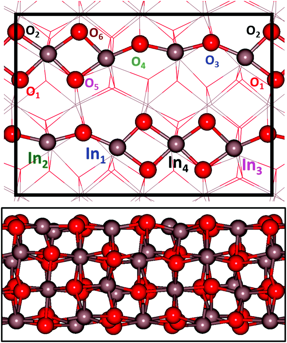 | ||
Fig. 1 Structural model of In2O3(110). The top figure shows the non-equivalent oxygen and indium sites in the chains that constitute the surface. A ball and stick representation is used to show the uppermost layer, while the other layers are presented as lines. The  surface cell is indicated with black lines. The bottom figure shows a lateral view of the four layer slab. A ball and stick model is in this case used for the slab representation. Atomic color code: indium (grey) and oxygen (red). surface cell is indicated with black lines. The bottom figure shows a lateral view of the four layer slab. A ball and stick model is in this case used for the slab representation. Atomic color code: indium (grey) and oxygen (red). | ||
3.2 H2 adsorption
The stability of In2O3(110) as a function of hydrogen chemical potential is investigated by use of ab initio thermodynamics. The pristine surface is studied together with five hydrogen coverages, namely 16% (low coverage limit), 50%, 66%, 83% and full coverage, see top panel of Fig. 2. The low coverage limit corresponds to one dissociated H2 molecule, whereas a full coverage is defined to be when all oxygen atoms in the topmost layer are occupied by hydrogen (six dissociated H2 molecules). The stability as a function of coverage is studied restricting the adsorption to homolytic dissociation as this is generally preferred.29 H2 dissociation over In2O3(110) is facile and we calculate a barrier of only 0.3 eV when the molecule is dissociated over the In2–O4 bridge. This is somewhat lower than a similar path on CeO2(111).50,51 | ||
| Fig. 2 Top: Structural models of In2O3(110) at various hydrogen coverages. Bottom: Surface stability of In2O3(110) as a function of hydrogen chemical potential (μH2) or pressure at a temperature of 573 K. The results are given with respect to the pristine surface at zero energy. Experimental conditions, 1–5 MPa (10–50 bar), are indicated by a purple fringe. Labels are color-coded in accordance with the top image. Atomic color code: indium (grey), oxygen (red), and hydrogen (white). | ||
We note that some of the formed OH-groups are displaced significantly from their oxygen position in the pristine slab. This is, in particular, true for O3 and O4, connected to the undercoordinated indium atoms at the surface. For example, O3 at 50% coverage, is displaced 0.43 Å from its pristine position. Furthermore, this oxygen changes its In–O–In distance from 2.125 and 2.116 Å on the pristine surface to In–OH–In: 2.458 and 2.126 Å. Similarly, O4 is displaced by as much as 2.40 Å from its position in the pristine surface. The interatomic In–O–In distances in this case change from 2.142 and 2.084 to 2.040 and 3.336 Å, respectively, upon hydroxylation. This result shows that the oxygen has a pronounced structural flexibility at high hydrogen coverages.
The stability of the different coverages as a function of hydrogen chemical potential (or hydrogen pressure at T = 573 K) is shown in the lower panel of Fig. 2. The Gibbs free energy of adsorption (ΔGads) is reported with reference to the pristine surface at zero energy. The experimentally relevant reaction conditions, 1 to 5 MPa, are highlighted in the figure. The phase diagram shows that the surface hydroxylates to 83% coverage under all relevant conditions. This surface coverage becomes the thermodynamically favorable condition already at a chemical potential of −0.98 eV (∼10−05 atm). These results are in qualitative agreement with experimental results of In2O3 hydroxylation upon hydrogen exposure.31 The average hydrogen adsorption energy on the surface is calculated to be −2.24, −1.65, −1.34, −1.44 and −1.24 eV for 16%, 50%, 66%, 83% and 100% coverage, respectively. Thus, increasing hydrogen coverage has a strong effect on the average hydrogen adsorption energy, which is reduced close to linearly with the coverage.
The surface cell has six different types of oxygen sites. The dependence of the adsorption energy on which sites are occupied is shown in Fig. 3.
 | ||
| Fig. 3 Relative energy of H2 adsorption on In2O3(110) at different coverages. Top panel shows the adsorption on a pristine surface. Dashed line at zero indicates energy of the pristine surface and H2(g). Inset depicts the initial state of the surface with site labeling. The adsorption modes in the high coverage limit of the surface are shown in the bottom two panels. The zero line in homolytic adsorption is the 83% covered surface with the empty sites changing for the different configurations. Heterolytic adsorption is considered with 12 hydrogen atoms. The reference system (zero line) is the 83% covered surface (homolytic adsorption). Homolytic sites are shown in red, heterolytic sites are shown in black and In–In sites are shown in blue. | ||
There are several possibilities for where to place the hydrogen atoms in the low coverage limit and we have explored 9 homolytic and 14 heterolytic configurations. We find that homolytic adsorption (OH–OH) is significantly more stable than heterolytic (OH–InH) adsorption. The adsorption energies for the OH–OH cases range from −1.73 to −2.36 eV. In comparison, heterolytic adsorption shows a much wider span of adsorption energies ranging from −0.02 to −1.23 eV. Homolytic adsorption on indium sites is in all cases unstable with respect to H2 in the gas phase. The large difference in adsorption energy between heterolytic and homolytic adsorption indicates weak metal hydride formation.
To further study the difference between homolytic and heterolytic dissociation, we explored the high coverage limit, see the middle and bottom panels of Fig. 3. The middle panel shows the relative energies for 9 different configurations with H2 dissociated homolytically on oxygen sites at a coverage of 83%, i.e. 5 H2 molecules. The stability shows a marked dependence on the configurations with a separation of 1.15 eV between the most unstable and stable configurations. The stable configuration is shown in Fig. 2, whereas the most unstable configuration has empty oxygen sites at the bridge between the (In–O)2 diamonds.
The possibility of heterolytic adsorption is investigated in the full coverage case (6 H2 molecules) with the structure in Fig. 2 (homolytic adsorption) as a reference. In contrast with the low coverage case, we find that having heterolytic hydrogen pairs could be preferred with respect to the all-oxygen case. In particular, it is configurations where the In4-site is occupied that have an enhanced stability. The most stable configuration is preferred by 0.61 eV with respect to the all-oxygen case. It should be noted that most configurations with In-sites occupied are unstable with respect to the all-oxygen case. The least stable configuration is 1.02 eV over the reference and includes an In-site at the edge of the diamonds. Despite the preference for occupation of In-sites at full coverage, it should be noted that, for entropic reasons, the 83% surface coverage retains the stable surface structure under MeOH-synthesis reaction conditions (see Fig. S5, ESI†).
The large spread in relative stability for the configurations in Fig. 3 underlines that care must be taken when modeling reactions on oxide surfaces. In the case of In2O3(110), the different cation sites have varying abilities to change oxidation state, which results in substantial energy differences between the different configurations.
The stabilization of heterolytic sites suggests a significant change in the electronic properties of In2O3(110) as the surface is hydroxylated. This is corroborated by the change in the band gap for the pristine and fully hydroxylated surfaces. The pristine surface has a band gap of 0.8 eV, which is close to the value for the bulk oxide, whereas the hydroxylated surface does not have any band gap. The total density of states (DOS) and the projected DOS (PDOS) are calculated for the bulk structure and pristine and hydrogen covered surfaces (all-oxygen configuration), see Fig. 4.
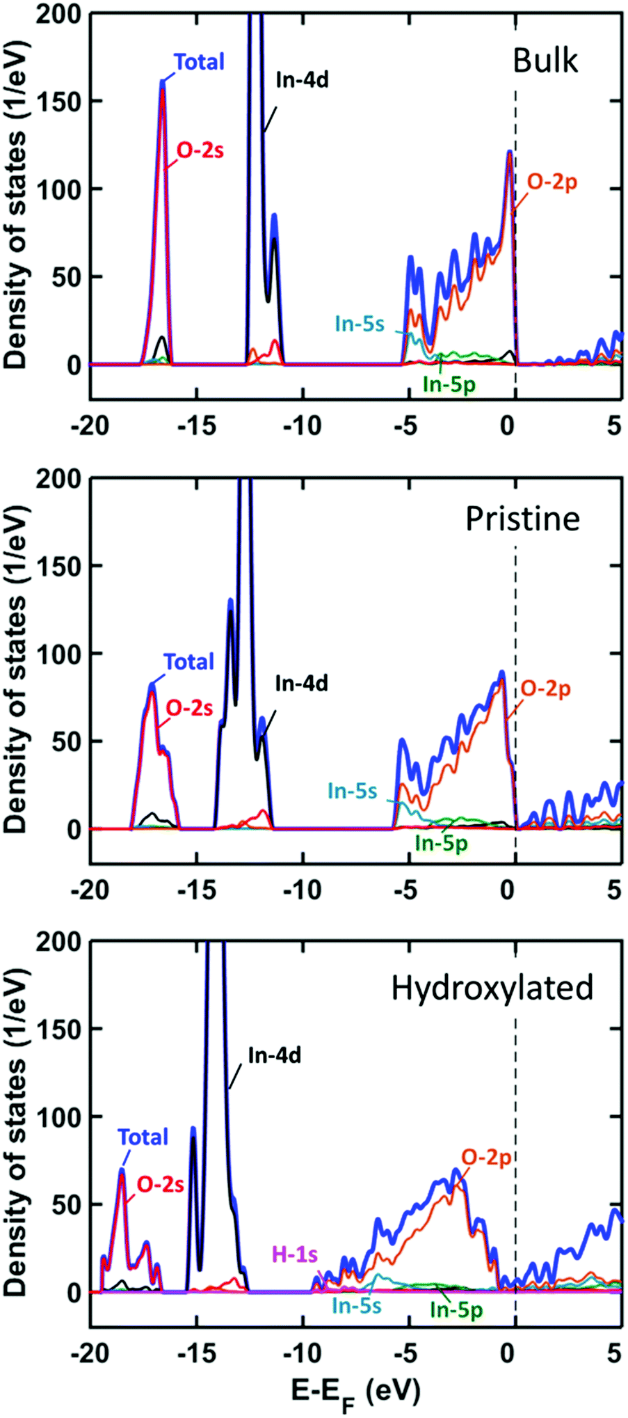 | ||
| Fig. 4 Density of states analysis as a function of hydrogen coverage on In2O3(110). Top panel shows DOS and PDOS of bulk structure. Middle and bottom panels show DOS and PDOS of pristine and fully hydroxylated In2O3(110), respectively. | ||
For the bulk system, the valence band has a spread of 5 eV and is dominated by O 2p with some hybridization with In 5s and 5p. The In 4d and O 2s states are located about 12 and 17 eV below the top of the valence band, respectively. The bands are widened for the In2O3(110) surface owing to the reduced coordination at the surface. Hydroxylation of the surface leads to a further widening where the valence band spans almost 10 eV. The H 1s contributions appear at the bottom of the valence band and above the Fermi energy.
A Bader charge analysis for the pristine and hydrogen-covered surface reveals a change in oxidation state of the undercoordinated indium sites (In1 and In2) upon hydroxylation. The charge difference for oxygen and indium atoms between the pristine and fully hydroxylated surface is shown in Fig. 5.
 | ||
| Fig. 5 Bader charge analysis of the topmost layer of hydroxylated In2O3(110). Charge localization is shown in dark blue. The charge on the light blue atoms is about ± 0.05 e. Hydrogen atoms are shown in white. | ||
The charge of the undercoordinated indium sites changes from 11.2 to 12.2 electrons upon hydroxylation. Given the charge relation obtained for the bulk structure, dividing the difference in Bader charge by 0.61 yields a change in oxidation state from +3 to close to +1. The change in charge state of the other indium and oxygen atoms is within 0.1 electrons upon hydroxylation, except for the undercoordinated In atoms at the backside of the slab showing a charge accumulation of about 0.25 electrons. The change in oxidation state is structurally manifested in elongation of the corresponding In–O bonds and a bond valence sum (BVS) analysis.52,53 The BVS of the undercoordinated In1 and In2 changes from ∼2.7 in the pristine surface to 1.0 upon hydroxylation, suggesting a close to +1 oxidation state for full coverage. The five-fold coordinated In3 and In4 show a small positive increase in their BVS upon hydroxylation, see the ESI.†
Changes of oxidation state upon surface hydroxylation are well known for ceria (CeO2),50,54 which is a reducible oxide. The adsorption of hydrogen CeO2(111) has been reported to be preferentially homolytic50,51 at a coverage of 50% and the oxidation state in this case changes from +4 to +3. Instead, H2 dissociation on non-reducible oxides such as MgO is heterolytic55 as the charge on the metal site does not change upon hydrogen adsorption.
3.3 H2O adsorption
It has been shown experimentally that, under methanol-synthesis conditions, the co-feeding of water into a H2/CO2 mix decreases the synthesis of methanol by 20%.24 To attain understanding of this behaviour, we have investigated the stability of In2O3(110) as a function of water chemical potential. Similar to hydrogen adsorption, we assume that water adsorption occurs dissociatively, where the H2O molecule dissociates and hydroxylates an oxygen site, while the OH group adsorbs on the indium site.Water adsorption has previously been shown to be preferably dissociative on In2O3(111).33 In the low coverage limit, the adsorption energies for molecular and dissociative adsorption were calculated to be −0.73 and −1.28 eV, respectively. For In2O3(110), we calculate the corresponding energies to be −0.78 and −1.46 eV. (See ESI† for the investigation of different adsorption sites.)
Six different water coverages on In2O3(110) were investigated, see the top panel of Fig. 6. As in the case of hydrogen adsorption, a full monolayer is defined to be when all oxygen sites in the supercell are hydroxylated. In addition, we consider 8%, 33%, 50%, 66% and 83% of full coverage.
 | ||
| Fig. 6 Top: Structural models of In2O3(110) at different H2O coverages. Bottom: Surface stability of In2O3(110) as a function of water chemical potential (μH2O) or pressure at a temperature of 573 K. The results are given with respect to the pristine surface at zero energy. Experimental conditions, 1–5 MPa (10–50 bar), are indicated by a purple fringe. Labels are color-coded in accordance with the top image. Atomic color code as in Fig. 2. | ||
We find that surface relaxation is less dramatic upon H2O adsorption than for H2 adsorption. The In–O bond lengths change only within 0.1 Å. The OH groups on the surface are found to align to form hydrogen bonds. This can be seen clearly at 8% coverage, where the OH group on In4 is oriented so that the hydrogen atom coordinates to the oxygen atom on the OH group at In2. In the case of 83% coverage, the relaxed structure includes a coexistence of molecular and dissociated H2O. In particular, the OH group placed at the In3 site picks up a hydrogen from the O2 site in the neighboring chain, forming H2O. Although this is the only case where this is observed in the present calculations, it indicates that a dynamic coexistence of dissociated and molecular water is possible.
The phase diagram, shown in the bottom panel of Fig. 6, shows that the surface hydroxylates readily to 83% coverage under relevant reaction conditions,24 at a chemical potential from −0.36 to −0.28 eV (10–50 atm at 573 K). In the same way as for the H2 adsorption, the 83% covered surface is the thermodynamically preferred coverage from a chemical potential of −0.32 eV. The average water adsorption energy, with respect to the gas phase molecule, for 8%, 33%, 50%, 66%, 83% and 100% is calculated to be, −1.46, −1.22, −1.15, −1.02, −0.96 and −0.80 eV, respectively. We notice that the variation in the average binding energy for water is smaller than that for the hydrogen adsorption case. An almost linear relation is found for the average adsorption energy of water as a function of water molecules on the surface (R2 = 0.98).
A Bader charge analysis was done on the 8%, 83% and full coverage surfaces. We find that, regardless of water coverage, charge transfer is minimal on the surface. All charge differences are within 0.1 electrons. This is consistent with the small structural changes in the surface upon water adsorption. The pronounced difference with respect to hydrogen adsorption is due to the fact that formation of OsH-groups at the surface (where Os is a surface oxygen) involves charge transfer from the Os site. In the case of hydrogen adsorption, the charge is transferred to indium whereas for water adsorption, the charge is transferred to the OH-group originating from water. The absence of changes in oxidation states for the indium cations upon water adsorption rationalizes the close to linear relation between average adsorption energy and coverage.
3.4 Oxygen vacancy creation by H2 reduction
The formation of oxygen vacancies on In2O3(110) by H2 reduction was investigated on both the pristine and high coverage limit surface structures. This was done by evaluating the Gibbs free energies of the two elementary steps along the reaction, | (4) |
The first step is dissociative adsorption of hydrogen forming a hydroxylated surface and the second step is the formation of water, which desorbs and forms an oxygen vacancy. Each non-equivalent oxygen site is considered for vacancy formation, see bottom panel of Fig. 7. On the pristine surface (top panel), the dissociated OH–OH configuration is in every case preferred with respect to water and vacancy formation. There is a considerable spread in the H2 adsorption energies ranging from −1.22 (O6) eV to −0.50 (O4) eV. The formation of water and a surface vacancy is endothermic with respect to a hydroxylated surface. The lowest temperature where water formation is favored (for O2) is 833 K. The stability of the final state is also strongly dependent on partial pressure of H2O. We calculate that a pressure of 10−5 bar is needed for this step to become thermodynamically preferred for O2 (see Fig. S8, ESI†). This means that, for the production of methanol from CO2 hydrogenation, this process becomes relevant only at very low conversion rates (∼10−5%), which is estimated from Dalton's law with a total pressure of Ptot = 31 bar.
 | ||
| Fig. 7 Gibbs free energy diagram for In2O3(110) reduction with H2. Top panel shows the elementary steps of the reaction on a pristine surface. Middle panel shows the reaction taking place on an 83% H-covered surface. Colored lines are coded in accordance with oxygen sites in the bottom panel. The partial pressure of water is set to 105 Pa (1 bar). | ||
Vacancy formation in the case of high hydrogen coverage is considered by adsorption at an 83% covered surface (two empty oxygen sites). Adsorption of one H2 molecule leads to a fully covered surface. The final structure after water formation is a hydroxylated surface with one vacancy and one empty oxygen site. Water can be formed by combining a range of different oxygen pairs. To guarantee that the most stable configuration is selected for each oxygen site, all contiguous oxygen pairs were examined for each oxygen, see the ESI.† The spread in stability is about 0.5 eV and the energetically preferred combination for each site is shown in Fig. 7.
The results at high hydrogen coverage are qualitatively different from the pristine surface. Firstly, the adsorption of hydrogen on these sites is in each case endothermic. Secondly, water formation is thermodynamically preferred and exothermic on three of the sites (O3, O4 and O6). Thus, our results suggest that H2 adsorption can lead to oxygen vacancies on a hydroxylated surface.
3.5 CO2 adsorption
Adsorption of carbon dioxide on oxygen-vacancy defective and pristine In2O3(110) was investigated with and without hydroxylation. The results for CO2 adsorption on a surface with one vacancy in the absence of hydroxylation are shown in the top panel of Fig. 8. | ||
| Fig. 8 Gibbs free energy diagram for oxygen vacancy quenching with CO2 on In2O3(110). Top panel shows the elementary steps of the reaction on a pristine surface. Bottom panel shows the reaction taking place on an 83% H-covered surface. The site-labeling follows Fig. 7. | ||
The considered steps are:
| In2O3(110)OV + CO2(g) → In2O3(110) + CO*OSurf → In2O3(110) + CO(g) | (5) |
The initial configuration is an oxygen-defective In2O3(110) and carbon dioxide in the gas-phase (In2O3(110)OV + CO2(g)). CO2 is adsorbed at the oxygen-vacancy, forming adsorbed CO on the surface (CO*OSurf on In2O3(110)). The final configuration is gas-phase CO and a pristine surface. The Gibbs free energy change is calculated at 573 K and a pressure of 1 MPa for CO2(g) and 0.1 MPa for CO(g), implying a relatively high conversion. The process was examined for each oxygen-vacancy site. We find that the CO2 adsorption onto the vacancies is thermodynamically unfavorable. In fact, local minima on the potential energy surface for adsorbed CO2 are found only for three of the cases, namely OV2, OV3 and OV4. Although they are local minima, the adsorption is endothermic with Gibbs free energies of 1.47, 0.60, and 0.71 eV, respectively. The corresponding electronic binding energies of CO2 are 0.29, −0.58 and −0.47 eV. The CO–OSurf structures formed at OV2, OV3 and OV4 have O–C–O angles of 139°, 130° and 127°, respectively. The bent structure signals that CO2 is charged; the O–C–O angle for CO2− in the gas phase is 135°. The surface oxygen to carbon interatomic distance (C–Os) is found to be about 1.3 Å, whereas the OsC–O bond length is about 1.2 Å. The indium–carbon distance (In–C) is about 2.3 Å. The structure from CO2 adsorption at OV3 is shown in Fig. 9(a).
 | ||
| Fig. 9 Top and side views of CO2 adsorbed on In2O3(110) under different surface conditions. The adsorption energy (eV) for each site is indicated. Site-labeling as in Fig. 1. Atomic color code as in Fig. 2. | ||
The oxygen sites that allow for the COOs state on the pristine surface are the sites with high vacancy formation energy (see ESI†). For these sites, vacancy formation is accompanied by reduction of the neighboring indium atoms whereas the charge is delocalized over the entire slab for the three sites where CO2 does not adsorb. Localization of charge on undercoordinated indium atoms appears to be a prerequisite for the formation of charged CO2 species. Formation of CO in the gas-phase is in all cases endothermic with respect to CO2 in the gas phase. This is in agreement with the experimental results in ref. 27, clearly showing the low tendency for the RWGS reaction over In2O3.
CO2 adsorption was examined also on the hydroxylated OV–In2O3(110) surface at a coverage of 83% hydrogen. As a starting point, we used the six vacancy structures discussed in Fig. 7. We only find stable adsorption configurations for two of the investigated vacancies, namely OV6 and OV2. However, the adsorption is strongly endothermic, being 1.28 and 1.71 eV, with electronic binding energies of 0.08 and 0.52 eV, respectively. The OsCO structure formed at OV6 has an O–C–O angle of θO–C–O = 124°, and Os–C and OsC–O bond lengths of 1.35 and 1.21 Å, respectively. The indium–carbon distance is in this case 2.24 Å. This structure is shown in Fig. 9(b). Adsorption at OV2 results in the OsCO structure that has a similar molecular structure but is located across the trench connecting two In2O3(110) chains.
Even if CO2 does not adsorb at four of the investigated vacancies, it may still adsorb close to the vacancy. Such local minima are obtained for OV1, OV4 and OV5. The electronic binding energy for CO2 in these configurations is found to be −0.48, 0.76 and 0.20 eV, respectively. However, the configurations are endothermic by 0.71, 1.40 and 1.95 eV, respectively, under typical reaction conditions (573 K, 4.0 MPa, and H2/CO2 = 3:1). An additional possibility is to adsorb far from the vacancy. The structure of such a case is shown in Fig. 9(c). This structure has an OV4 vacancy and CO2 adsorbed between In1 and In4. The electronic binding energy is −0.48 eV.
As adsorption at and close to oxygen vacancies appears to be arduous, the adsorption of CO2 on a defect-free surface is investigated. Adsorption on the pristine surface is investigated exclusively over the oxygen sites, while adsorption on the fully hydroxylated surface is explored over indium sites. For the pristine surface, we find that CO2 binds at every oxygen site in a CO32− configuration. The energetic and structural descriptors for the adsorbed molecule are presented in Table 1 and the case of adsorption at O3 is visualized in Fig. 9(d). Adsorption on all sites has a negative electronic binding energy and the Gibbs free energies are exothermic for O3, O4 and O6. The adsorbed molecules could in these cases be characterized as carbonates; the O–C–O angles are close to 120° and the three C–O bonds are within 0.2 Å. Moreover, the excess charge on the OsCO2 species is only 0.21 electrons with respect to the pristine surface and CO2 in the gas phase.
| ΔG (eV) | E b (eV) | θ O–C–O (°) | C–O1 (Å) | C–O2 (Å) | C–OSurf (Å) | |
|---|---|---|---|---|---|---|
| O1 | 0.44 | −0.75 | 126 | 1.32 | 1.23 | 1.40 |
| O2 | 0.64 | −0.54 | 129 | 1.30 | 1.24 | 1.40 |
| O3 | −0.19 | −1.37 | 125 | 1.29 | 1.29 | 1.34 |
| O4 | −0.06 | −1.24 | 128 | 1.30 | 1.27 | 1.35 |
| O5 | 0.71 | −0.47 | 128 | 1.29 | 1.25 | 1.40 |
| O6 | −0.03 | −1.21 | 122 | 1.29 | 1.29 | 1.34 |
It is also possible that CO2 adsorbs at an OH group, forming a bicarbonate (HCO3), which was investigated at the low hydrogen coverage limit (16%). However, we do not find any local minimum for CO2 adsorbed at an OH-group. Without exploring barriers, we find HCO3 adsorbed at In–In bridge configurations involving O3–H or O6–H with adsorption energies of −0.10 and −0.13 eV, respectively.
The surface is hydroxylated under the reaction conditions, and as the next step, we investigated CO2 adsorption on the fully hydroxylated In2O3(110). Assuming that CO2 is bridging two indium sites, there are four non-equivalent such sites per chain. For each site, the molecule can bind the carbon end of the molecule to two different indium sites, giving in total eight configurations, see Table 2. Four of the investigated adsorption configurations yield minima on the potential energy surface. To describe the configurations, we use the nomenclature IniInj, where i and j indicate the indium to which carbon and oxygen bind, respectively. The indium atoms are numbered as in Fig. 1. An example of these configurations (In1In2) is shown in Fig. 9(e).
| ΔG (eV) | E b (eV) | θ O–C–O (°) | C–O1 (Å) | C–O2 (Å) | C–OSurf (Å) | |
|---|---|---|---|---|---|---|
| In1In2 | 0.19 | −0.99 | 126 | 1.28 | 1.252 | 2.25 |
| In2In1 | 0.47 | −0.71 | 131 | 1.26 | 1.244 | 2.32 |
| In3In2 | 0.67 | −0.51 | 130 | 1.29 | 1.218 | 2.33 |
| In1In4 | 0.73 | −0.45 | 133 | 1.28 | 1.215 | 2.38 |
We find that adsorption on the fully hydroxylated surface has electronic binding energies in the range from −0.45 to −0.99 eV. However, the configurations are endothermic under typical reaction conditions. All the four stable configurations involve the undercoordinated In1 and In2 sites. The adsorption energy is strongly dependent on the orientation of the molecule. One example is the In1In2 site, where reorientation into In2In1 makes the adsorption 0.26 eV less stable. Changing the orientation of In3In2 and In1In4 yields configurations that are not local minima on the potential energy surfaces. The results show a strong local dependence, again related to the ability of undercoordinated In-sites to change oxidation state. CO2 is adsorbed in a CO2− configuration as corroborated by the Bader analysis yielding one excess electron on the adsorbate. The charging of the CO2 is evident also in the structure where the θO–C–O angle is about 130°.
The stable hydroxylation coverage was found to be 83% and we have considered CO2 adsorption onto a surface with this coverage. The relaxed structure is shown in Fig. 9(f). The electronic binding energy is −0.08 eV and the adsorption is endothermic by 1.10 eV. This structure should, in similarity with Fig. 9(d), be characterized as a carbonate-like species. The θO–C–O angle is 130° and the C–O bonds are 1.410, 1.277 and 1.258 Å for C–Os and the others, respectively.
Having explored CO2 adsorption on pristine and hydroxylated In2O3(110) with and without oxygen defects, we calculated the barrier for adsorption in three relevant cases, see Fig. 10. The three cases are: (I) CO2 adsorption at an oxygen vacancy for a hydroxylated surface, (II) CO2 adsorption on a hydroxylated surface with one oxygen vacancy but not at the vacancy, and (III) CO2 adsorbed on the fully hydroxylated surface without vacancies.
 | ||
| Fig. 10 Gibbs free energy landscape for CO2 adsorption on three different In2O3(110) surfaces. The free energies are calculated at T = 573 K, PH2 = 3 MPa, PH2O = 0.1 MPa and PCO2 = 1 MPa. | ||
The starting point for the three paths is a hydroxylated surface at 83% coverage as that coverage is predicted to be the thermodynamically preferred situation under the reaction conditions, see Fig. 2. The first step in the reaction is H2 adsorption yielding a fully hydroxylated surface. This step is endothermic by 1.26 eV. In paths I and II, two different types of vacancies are created by the formation of water. The vacancy in I is created by removing O6, which yields the most stable site for CO2 adsorption (Fig. 8). The most stable surface vacancy corresponds to removing O4, which is done in path II. Path III proceeds without the formation of vacancies.
CO2 adsorption is associated with a barrier that is 1.67, 0.82 and 0.48 eV for the three paths I, II and III, respectively. The high barrier in the case of path I is related to the breaking of an In–In bond. The bond distance is 3.1 Å with the vacancy and 3.9 Å once it is filled with CO2. The considerably lower barriers for adsorption along the paths of II and III can be understood by the fact that no bonds are broken along these paths. We attribute the low barrier in path III to the reduced state of the undercoordinated indium atoms (In1+), which upon CO2 adsorption again take an In3+ state in combination with the possibility to make hydrogen bonds in the final state. The final configurations of the adsorbed CO2− are endothermic with respect to the fully hydroxylated surface for I and III, whereas it is exothermic for II. We note that desorption of CO2 should be facile for II while there are clear barriers for I and III.
Reduction of the In2O3(110) surface by H2 forming water is exothermic for some of the oxygen sites in the surface. However, the free energy diagram suggests that vacancies are not crucial for activation of CO2 on In2O3(110). Instead, hydroxylation by H2 appears to be important as it reduces the oxidation state of indium surface atoms and provides possibilities for hydrogen bonding. In this sense, oxygen vacancies appear to be spectators in the CO2 adsorption process.
4 Conclusions
We used density functional theory calculations to investigate CO2 adsorption on In2O3(110). The importance of H2 and H2O hydroxylation as well as oxygen vacancies has been explored.A thermodynamic analysis reveals that the surface is heavily hydroxylated under all relevant experimental conditions for methanol-synthesis. Hydroxylation from H2 and H2O results in surfaces with significantly different chemical properties. H2 dissociates homolytically on the surface up to 83% coverage. The formation of surface OH-groups reduces In atoms at the surface, forming In1+ sites. It is mainly undercoordinated surface atoms that are reduced. Water adsorption does not lead to a reduction of In-sites. Instead, all surface atoms retain the pristine oxidation state.
Creation of oxygen vacancies by water formation from adsorbed H2 is found to be thermodynamically preferred in the limit of high hydrogen coverages. Thus, it is reasonable to assume that In2O3(110) surfaces contain vacancies under the reaction conditions. However, we found that vacancies do not facilitate CO2 adsorption. The barrier for adsorption at the vacancy is high due to the breaking of In–In bonds, thus CO2 does not seem to quench oxygen vacancies. CO2 is instead preferably adsorbed on hydroxylated vacancy-free surfaces. CO2 is adsorbed by accepting one electron from the surface, a process that is facilitated by the reduced state of the surface atoms upon H2 hydroxylation.
Our results are in agreement with experiments showing a suppression of the reverse water gas shift (RWGS) reaction over In2O3.27 The finding that oxygen vacancies do not play a significant role in CO2 adsorption but instead may hinder the reaction may elucidate the experimental observation that In2O3 supported on ZrO2 increases the activity.24 The role of ZrO2 could potentially be a reduction of the tendency to form vacancies in the In2O3-phase. Our results provide a handle to develop In2O3-based systems for CO2 hydrogenation to CH3OH. Doping of In2O3 should be done in order to reduce vacancy formation while still allowing for a redox behaviour of the indium ions.
Conflicts of interest
There are no conflicts to declare.Acknowledgements
Financial support from the Knut and Alice Wallenberg Foundation through the project “Atomistic design of catalysts” (No: KAW 2015.0058) is gratefully acknowledged. Additional support has been obtained from the Swedish Research Council (2016-05234) and Swedish Energy Agency. The calculations have been performed at C3SE (Göteborg), Uppmax (Uppsala) and PDC (Stockholm) through a SNIC grant.Notes and references
- S. Zimov, E. Schuur and F. Chapin, Science, 2006, 312, 1612–1613 CrossRef CAS PubMed.
- B. Santer, M. Wehner, T. Wigley, R. Sausen, G. Meehl, K. Taylor, C. Ammann, J. Arblaster, W. Washington, J. Boyle and W. Bruggemann, Science, 2003, 301, 479–483 CrossRef CAS PubMed.
- G. Meehl and C. Tebaldi, Science, 2004, 305, 994–997 CrossRef CAS PubMed.
- J. Hansen, M. Sato, R. Ruedy, K. Lo, D. W. Lea and M. Medina-Elizade, PNAS, 2006, 103, 14288–14293 CrossRef CAS PubMed.
- G. A. Olah, Angew. Chem., Int. Ed., 2005, 44, 2636–2639 CrossRef CAS PubMed.
- G. A. Olah, A. Goeppert and G. K. S. Prakash, J. Org. Chem., 2009, 74, 487–498 CrossRef CAS PubMed.
- G. A. Olah, G. K. S. Prakash and A. Goeppert, J. Am. Chem. Soc., 2011, 133, 12881–12898 CrossRef CAS PubMed.
- A. Goeppert, M. Czaun, J.-P. Jones, G. K. S. Prakash and G. A. Olah, Chem. Soc. Rev., 2014, 43, 7995–8048 RSC.
- M. D. Porosoff, B. Yan and J. G. Chen, Energy Environ. Sci., 2016, 9, 62–73 RSC.
- A. Alvarez, A. Bansode, A. Urakawa, A. V. Bavykina, T. A. Wezendonk, M. Makkee, J. Gascon and F. Kapteijn, Chem. Rev., 2017, 117, 9804–9838 CrossRef CAS PubMed.
- S. Kattel, P. Liu and J. G. Chen, J. Am. Chem. Soc., 2017, 139, 9739–9754 CrossRef CAS PubMed.
- R. M. Navarro, M. A. Pena and J. L. G. Fierro, Chem. Rev., 2007, 107, 3952–3991 CrossRef CAS PubMed.
- A. I. Olivos-Suarez, A. Szecsenyi, E. J. M. Hensen, J. Ruiz-Martinez, E. A. Pidko and J. Gascon, ACS Catal., 2016, 6, 2965–2981 CrossRef CAS.
- K. Cheng, J. Kang, D. L. King, V. Subramanian, C. Zhou, Q. Zhang and Y. Wang, in Advances in catalysis for syngas conversion to hydrocarbons, Advances in Catalysis, ed. C. Song, 2017, vol. 60, pp. 125–208 Search PubMed.
- M. Behrens, F. Studt, I. Kasatkin, S. Kuehl, M. Haevecker, F. Abild-Pedersen, S. Zander, F. Girgsdies, P. Kurr, B.-L. Kniep, M. Tovar, R. W. Fischer, J. K. Norskov and R. Schloegl, Science, 2012, 336, 893–897 CrossRef CAS PubMed.
- T. Reichenbach, K. Mondal, M. Jaeger, T. Vent-Schmidt, D. Himmel, V. Dybbert, A. Bruix, I. Krossing, M. Walter and M. Moseler, J. Catal., 2018, 360, 168–174 CrossRef CAS.
- M. Hus, D. Kopac and B. Likozar, ACS Catal., 2019, 9, 105–116 CrossRef CAS.
- B. Hagman, A. Posada-Borbon, A. Schaefer, M. Shipilin, C. Zhang, L. R. Merte, A. Hellman, E. Lundgren, H. Gronbeck and J. Gustafson, J. Am. Chem. Soc., 2018, 140, 12974–12979 CrossRef CAS PubMed.
- J. Sun, I. Metcalfe and M. Sahibzada, Ind. Eng. Chem. Res., 1999, 38, 3868–3872 CrossRef CAS.
- M. Twigg and M. Spencer, Top. Catal., 2003, 22, 191–203 CrossRef CAS.
- J. Graciani, K. Mudiyanselage, F. Xu, A. E. Baber, J. Evans, S. D. Senanayake, D. J. Stacchiola, P. Liu, J. Hrbek, J. Fernandez Sanz and J. A. Rodriguez, Science, 2014, 345, 546–550 CrossRef CAS PubMed.
- P. Gao, S. Li, X. Bu, S. Dang, Z. Liu, H. Wang, L. Zhong, M. Qiu, C. Yang, J. Cai, W. Wei and Y. Sun, Nat. Chem., 2017, 9, 1019–1024 CrossRef CAS PubMed.
- S. Kattel, B. Yan, Y. Yang, J. G. Chen and P. Liu, J. Am. Chem. Soc., 2016, 138, 12440–12450 CrossRef CAS PubMed.
- O. Martin, A. J. Martin, C. Mondelli, S. Mitchell, T. F. Segawa, R. Hauert, C. Drouilly, D. Curulla-Ferre and J. Perez-Ramirez, Angew. Chem., Int. Ed., 2016, 55, 6261–6265 CrossRef CAS PubMed.
- T. Umegaki, K. Kuratani, Y. Yamada, A. Ueda, N. Kuriyama, T. Kobayashi and Q. Xu, J. Power Sources, 2008, 179, 566–570 CrossRef CAS.
- H. Lorenz, W. Jochum, B. Kloetzer, M. Stoeger-Pollach, S. Schwarz, K. Pfaller and S. Penner, Appl. Catal., A, 2008, 347, 34–42 CrossRef CAS.
- T. Bielz, H. Lorenz, P. Amann, B. Kloetzer and S. Penner, J. Phys. Chem. C, 2011, 115, 6622–6628 CrossRef CAS.
- J. Ye, C. Liu, D. Mei and Q. Ge, ACS Catal., 2013, 3, 1296–1306 CrossRef CAS.
- J. Ye, C. Liu and Q. Ge, J. Phys. Chem. C, 2012, 116, 7817–7825 CrossRef CAS.
- M. S. Frei, M. Capdevila-Cortada, R. Garcia-Muelas, C. Mondelli, N. Lopez, J. A. Stewart, D. C. Ferre and J. Perez-Ramirez, J. Catal., 2018, 361, 313–321 CrossRef CAS.
- T. Bielz, H. Lorenz, W. Jochum, R. Kaindl, F. Klauser, B. Kloetzer and S. Penner, J. Phys. Chem. C, 2010, 114, 9022–9029 CrossRef CAS.
- D. Albani, M. Capdevila-Cortada, G. Vile, S. Mitchell, O. Martin, N. Lopez and J. Perez-Ramirez, Angew. Chem., Int. Ed., 2017, 56, 10755–10760 CrossRef CAS PubMed.
- M. Wagner, P. Lackner, S. Seiler, A. Brunsch, R. Bliem, S. Gerhold, Z. Wang, J. Osieck, K. Schulte, L. A. Boatner, M. Schmid, B. Meyer and U. Diebold, ACS Nano, 2017, 11(11), 11531–11541 CrossRef CAS PubMed.
- G. Kresse and J. Hafner, Phys. Rev. B: Condens. Matter Mater. Phys., 1993, 47, 558–561 CrossRef CAS PubMed.
- G. Kresse and J. Hafner, Phys. Rev. B: Condens. Matter Mater. Phys., 1994, 49, 14251–14269 CrossRef CAS PubMed.
- G. Kresse and J. Furthmüller, Comput. Mater. Sci., 1996, 6, 15–50 CrossRef CAS.
- G. Kresse and J. Furthmüller, Phys. Rev. B: Condens. Matter Mater. Phys., 1996, 54, 11169–11186 CrossRef CAS PubMed.
- J. P. Perdew, K. Burke and M. Ernzerhof, Phys. Rev. Lett., 1996, 77, 3865–3868 CrossRef CAS PubMed.
- P. E. Blochl, Phys. Rev. B: Condens. Matter Mater. Phys., 1994, 50, 17953–17979 CrossRef PubMed.
- G. Kresse and D. Joubert, Phys. Rev. B: Condens. Matter Mater. Phys., 1999, 59, 1758–1775 CrossRef CAS.
- H. J. Monkhorst and J. D. Pack, Phys. Rev. B: Condens. Matter Mater. Phys., 1976, 13, 5188–5192 CrossRef.
- G. Henkelman, A. Arnaldsson and H. Jonsson, Comput. Mater. Sci., 2006, 36, 354–360 CrossRef.
- K. Reuter and M. Scheffler, Phys. Rev. B: Condens. Matter Mater. Phys., 2002, 65, 0354061 CrossRef.
- Q. Sun, K. Reuter and M. Scheffler, Phys. Rev. B: Condens. Matter Mater. Phys., 2003, 67, 2054241 Search PubMed.
- P. J. Linstrom and W. G. Mallard, NIST Chemistry WebBook, NIST Standard Reference Database Number 69; National Institute of Standards and Technology, Gaithersburg, MD, http://webbook.nist.gov, 2005, [Online; Accessed 3-December-2018] Search PubMed.
- G. Henkelman, B. Uberuaga and H. Jonsson, J. Chem. Phys., 2000, 113, 9901–9904 CrossRef CAS.
- P. Erhart, A. Klein, R. G. Egdell and K. Albe, Phys. Rev. B: Condens. Matter Mater. Phys., 2007, 75, 1532051 CrossRef.
- S. Z. Karazhanov, P. Ravindran, P. Vajeeston, A. Ulyashin, T. G. Finstad and H. Fjellvag, Phys. Rev. B: Condens. Matter Mater. Phys., 2007, 76, 0751291 CrossRef.
- T. de Boer, M. F. Bekheet, A. Gurlo, R. Riedel and A. Moewes, Phys. Rev. B: Condens. Matter Mater. Phys., 2016, 93, 1552051 CrossRef.
- J. Carrasco, G. Vile, D. Fernandez-Torre, R. Perez, J. Perez-Ramirez and M. Veronica Ganduglia-Pirovano, J. Phys. Chem. C, 2014, 118, 5352–5360 CrossRef CAS.
- M. Garcia-Melchor and N. Lopez, J. Phys. Chem. C, 2014, 118, 10921–10926 CrossRef CAS.
- I. D. Brown, Chem. Rev., 2009, 109, 6858–6919 CrossRef CAS PubMed.
- J. A. Enterkin, A. E. Becerra-Toledo, K. R. Poeppelmeier and L. D. Marks, Surf. Sci., 2012, 606, 344–355 CrossRef CAS.
- M. Van den Bossche and H. Grönbeck, J. Phys. Chem. C, 2017, 121, 8390–8398 CrossRef CAS.
- H.-Y. T. Chen, L. Giordano and G. Pacchioni, J. Phys. Chem. C, 2013, 117, 10623–10629 CrossRef CAS.
Footnote |
| † Electronic supplementary information (ESI) available: Details of bulk calculations, thermodynamic analyses, and bond valence sum analysis. See DOI: 10.1039/c9cp04097h |
| This journal is © the Owner Societies 2019 |