
 Open Access Article
 This Open Access Article is licensed under a
 Creative Commons Attribution 3.0 Unported Licence
Heavy atom labeling enables silanol defect visualization in silicalite-1 crystals†
Teng
Li
 a,
Frank
Krumeich
a,
Johannes
Ihli
b,
Zhiqiang
Ma
a,
Takashi
Ishikawa
b,
Ana B.
Pinar
b and
Jeroen A.
van Bokhoven
*ab
a,
Frank
Krumeich
a,
Johannes
Ihli
b,
Zhiqiang
Ma
a,
Takashi
Ishikawa
b,
Ana B.
Pinar
b and
Jeroen A.
van Bokhoven
*ab
aInstitute for Chemical and Bioengineering, ETH Zurich, 8093 Zurich, Switzerland. E-mail: jeroen.vanbokhoven@chem.ethz.ch; Tel: +41 44 632 55 42
bPaul Scherrer Institute, 5232 Villigen, Switzerland
First published on 14th December 2018
Abstract
Using heavy-atom labeling in conjunction with electron microscopy, we here visualize the distribution of point defects, i.e. internal silanol groups, in silicalite-1 zeolites at the single crystal level.
Defect sites are among the dominant factors defining the activity, functionality and stability of heterogeneous catalysts.1–5 Among the manifold catalysts with crystalline structures, zeolites are a fundamental pillar of the refining and petrochemical industries.6–8 These microporous materials find utilization in catalysis and separation. The type and the density of structural defects strongly influence the catalytic activity.9–11 For example, in the methane to hydrocarbon process, such defects can accommodate coke molecules which leads to a more pronounced deactivation of catalysts.11 In addition, the distribution of structural defects is also important, since it has an impact on the structural stability. This is of particular industrial interest as simple base leaching has been shown to be an effective means to produce mesoporous or hollow zeolites.12,13 Studies suggest that the dissolution and thus mesopore formation are mainly driven by inherent inhomogeneous aluminum distribution14,15 and/or appearance of defect sites.16,17 The formation of mesopores preferentially commences at the location of defects, as such an area is easily attacked and eliminated.
Silicate zeolites attract lots of attention due to their high thermal stability and hydrophobicity.18,19 Such materials, built from corner-sharing SiO4− tetrahedra, possess two types of silanol groups, either located on the outermost surface of the crystals or within their interior in the micropores. The internal silanol groups or nests, originating due to the absence of silicon atoms in the framework, are regarded as a specific type of point defect of zeolites.20,21 Unlike intergrowth and stacking faults that have been identified by electron microscopy,22–24 a direct observation of local defects with electron microscopy is rather difficult. This is due to the required spatial resolution, the low atomic number of silicon, the associated lack of image contrast, and the sensitivity of zeolite materials to the electron beam. Fourier-transform infrared (FT-IR) spectroscopy and nuclear magnetic resonance (NMR) spectroscopy are mainly used to identify the presence and the density of the silanol groups,25,26 but they do not provide the needed spatial resolution to locate defects. Moreover, measuring the bulk material that has numerous crystals only gives an average result, and different crystals may possess different distributions of silanol defects. What still remains unsolved is how to visualize the location and distribution of these defects at the single crystal level. Recently, with the help of fluorescent or fluorescently labeled species, the location of real active sites was spatially identified in one zeolite crystal by fluorescence microscopy (FM).27–29 The strategy of labeling may help to identify silanol defects if we can increase the contrast between the defective and the defect-free areas under electron beam conditions.
Herein, we make use of well-defined chemistry and reactivity of defect sites to visualize the distribution of silanol groups within individual crystals of silicalite-1 zeolites, and further disclose the relationship between defects and mesopore formation. This was made possible by grafting an organic moiety with an amino functional group onto the silanol defect.30,31 Exposure to a suitable gold precursor resulted in heavy-atom labeled silicalite-1 with a sufficient image contrast to be observed using electron microscopy.
Fig. 1a and c show electron micrographs of the S1 (defect-rich silicalite-1) crystals which were synthesized in basic media. The crystals have a hexagonal shape of size between 200 and 300 nm. Taking advantage of hybrid pixel detectors in electron crystallography with a rotation method, our recent work shows that the S1 crystals are single crystals and not intergrown.32 After mild leaching in a 0.1 M NaOH solution, mesopores were introduced (Fig. 1b and d). The preferential dissolution of the inner part was observed from both TEM and SEM. Furthermore, base leaching under more severe conditions leads to the formation of a hollow-like structure, manifesting a higher stability of the rim of crystals (Fig. S1, ESI†).33 The crystallinity increased by 20% after mild leaching (Fig. S2a, ESI†). Regarding the –OH groups, three main peaks were observed from the infrared spectrum (Fig. S2b, ESI†), i.e., which can be ascribed to the external silanols, the internal silanols and the silanol nests.34 The presence of silanol nests and the high intensity ratio between 3726 cm−1 and 3745 cm−1 (I3726/I3745 ≈ 8.7) implied the existence of a significant number of defects. The mild leaching eliminated most defects as the peak intensity at 3726 cm−1 and 3500 cm−1 decreased significantly. The 29Si MAS NMR result also confirmed the diminution of silanol groups. The Q3 (HO-Si-[(OSi)3]) group decreased much upon leaching (Fig. S2c, ESI†).
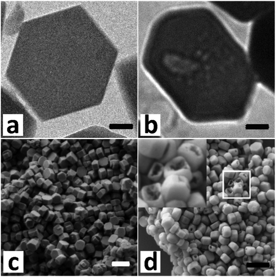 | ||
| Fig. 1 TEM and SEM images of (a and c) the defect-rich silicalite-1 and (b and d) the corresponding crystals leached in 0.1 M NaOH for 10 h. Scale bars represent 50 nm (a and b) and 500 nm (c and d). The TEM image in (b) was recorded in strong underfocus to enhance the pore visibility. | ||
Organic functionalization of ordered mesoporous materials has seen significant progress.35–39 Studies have proved that coupling agents of large molecular size can be more efficiently grafted than their smaller counterparts.40–42 However, their grafting onto the internal surface of zeolites is inhibited by the limited micropore size. To functionalize the internal surface of silicalite-1 crystals efficiently, the size of the coupling molecule should be tuned to fit zeolite micropores. 3-Amino-1-propanol is selected here due to its linear structure and reactivity to silanol groups (Scheme 1).31 The –OH group condenses with the silanol group to form a C–O–Si linkage, fixing the molecule onto the defect site. The amino group is subsequently used to anchor heavy atoms as labels. Gold is selected as the marker due to its strong interaction with the amino groups.43,44
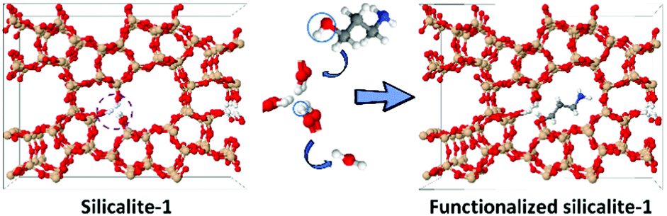 | ||
| Scheme 1 An illustration of the functionalization process of silicalite-1. The silanol groups react with 3-amino-1-propanol, forming a covalent bond and realizing the introduction of amino groups for subsequently anchoring gold atoms. Color scheme: brown (Si), red (O), white (H), blue (N) and gray (C). | ||
The main grafting work strictly followed a published paper.31 The weight loading of the organic moiety was measured by thermal gravimetric analysis (TGA) (Fig. S3a, ESI†). For S1, the weight loss before 150 °C (≈1 wt%) can be assigned to the removal of water, whereas, the decrease after 550 °C was caused by the condensation of neighboring silanol groups to form Si–O–Si linkages.45,46 A significant weight loss (4.7 wt%) was observed for the functionalized S1 between 250 and 550 °C, caused by the removal of the organic moiety. The total organic loading is nearly 0.82 mmol g−1. The external surface grafting is inevitable but that part can be estimated to be as much as 0.11 mmol g−1 (see the ESI†). The 29Si MAS NMR spectrum shows a significant reduction of the Q3 groups after grafting (Fig. S3b, ESI†). This is more obvious from the 29Si CP MAS NMR spectrum since the signals of silicon nuclei bonded to OH groups can be enhanced by the protons in proximity.17 The Q3/Q4 ratio decreased from 3.55 to 0.33 after grafting and the Q2 groups in S1 were eliminated completely (Fig. S3c, ESI†).
To introduce gold, the functionalized S1 was mixed with an aqueous solution of HAuCl4 at a pH of 2.5 (10−3 mol L−1). Then, the solid was washed thoroughly and dried at room temperature. The defect-labeled S1 presents a light yellow color. The gold loading determined by atomic absorption spectroscopy (AAS) was 0.7 wt%, nearly 0.036 mmol g−1, much lower than the amount of the organic moiety. This indicated that not all labeled silanols were accessible by gold. One reason could be the blocking of the accessibility of the gold precursor species to the more interior part by the organic moieties that are located on or close to the external surface. The significant decrease in the micropore volume (∼45%) and the external surface area (∼80%) confirmed the existence of diffusion limitation for the functionalized S-1 (Table S1, ESI†). Adding the gold precursor into pristine S1 did not show the presence of any gold in the material, which suggested that the introduced amino groups did play a role in the attraction of gold atoms. Fig. 2a and b present the electron micrographs of the defect-labeled S1. Overall, the original shape of the crystals was preserved. A closer look at the individual crystals shows small white spots with a size between 0.8 and 1 nm (Fig. 2c–f), which were gold clusters (Z-contrast). The small sizes of gold clusters were also confirmed by XRD with no gold peak visible (Fig. S5, ESI†). Well-resolved diffraction peaks also indicated that the introduction of amino groups and gold clusters did not create new and obvious defects. The size of the clusters was larger than the pore diameter (0.55 nm), but close to the size of the channel intersection (1 nm).47 Interestingly, the gold clusters were more heterogeneously distributed. Their concentration was high in the crystal core and on the outermost layer, whereas fewer gold clusters were detected within a 10 nanometer rim measured from the surface of the crystal. It indicated that the 10-nanometer-area from the edge possesses fewer defects than the core part. To further decrease the size of gold clusters or obtain gold single atoms, we also applied another more dilute gold solution (10−4 mol L−1). However, after careful examination we were not able to find any trace of gold though elemental analysis indicated its existence (Fig. S6, ESI†). The reason was possibly the presence of the atomically dispersed gold within a thick crystal, which did not provide enough contrast for visualization. The formation of clusters was due to the aurophilicity of gold, i.e. the tendency to form Au–Au bonds.48 This should happen on the defect site or at least close to the defective area as amino groups provided the anchoring site for landing initial gold atoms. The uneven spatial distribution of defects may be related to the crystallization process, as a slower growth rate at the later stage can lead to a better crystallized structure with fewer silicon vacancies and therefore a lower concentration of silanol defects.49,50
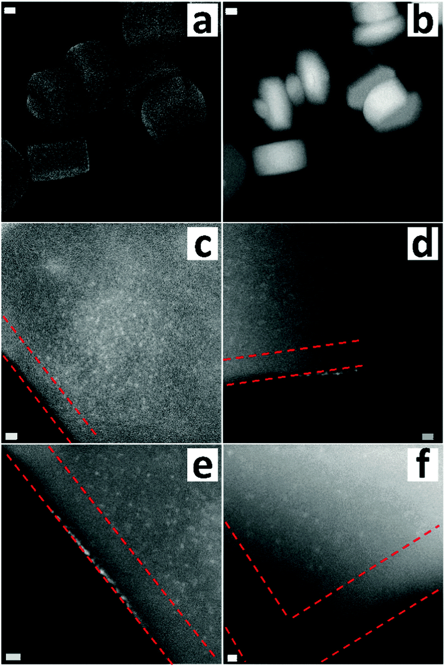 | ||
| Fig. 2 (a) Secondary electron STEM and (b-f) HAADF-STEM images of defect-labeled S1. Scale bars represent 50 nm (a and b), 5 nm (c–e) and 2 nm (f). The red dashed line indicates a defect-starved rim with about 10 nm thickness. | ||
The defect-poor silicalite-1 sample with monoclinic symmetry (S2) was also prepared and investigated here. The pristine sample had two size populations, one with crystals between 150 and 250 nm and the other one with particles between 20 and 30 nm. The small particles may be metastable silica nanoparticle precursors since most were attached on the big ones (Fig. S7, ESI†).51 Leaching in the 0.1 M NaOH solution eliminated most of the small particles, and a harsher treatment in the 0.2 M NaOH solution gave rise to the formation of mesopores in the big crystals. Unlike the leached S1 crystals, the mesopores were randomly distributed in the leached S2 crystals, suggesting that S2 did not have a preferential location of the defects. The intensity of the external silanols was much higher than that of the internal silanols (Fig. S8b, ESI†). The Q3 signal was not observed in the 29Si MAS NMR spectrum (Fig. S8c, ESI†). Such a relatively defect-poor framework structure was further confirmed as its NMR signals can be attributed to 24 inequivalent T sites within the monoclinic symmetry (Fig. S8d and Table S2, ESI†).52 The labeling of the defects for S2 was carried out following the above described method. The lower gold loading (0.29 wt%) confirmed a low concentration of silanol groups. Fig. 3 shows the distribution of gold clusters, and the typical size of the clusters was between 1.0 and 1.5 nm, larger than that in the previous case. Such clusters were mainly located on the outermost layer of crystals. This distribution is expected since S2 has more external silanols and fewer inner defects.
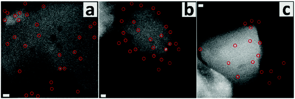 | ||
| Fig. 3 STEM images of the defect-labeled S2. Scale bars are 10 nm (a) and 5 nm (b and c). Typical gold clusters on the same one crystal are indicated by red circles. | ||
The inhomogeneous aluminum distribution, such as Al-zoning, can be probed by electron microscopy and associated energy-dispersive X-ray (EDX) spectroscopy.15,53 However, any distribution of point defects in zeolites has been so far only postulated. Creating a new method to visualize the distribution of such defects is necessary, since this enables getting a more direct insight into defect chemistry. Regarding the defect-rich silicalite-1, i.e. S1, a defect-starved rim with about 10 nm thickness was identified. As a result, the rim part was robust while more pores formed in the core during base leaching. Such a consistency was further confirmed for the defect-poor sample (S2) since it showed a much lower concentration and a random distribution of markers, and consequently a non-preferential mesopore formation.
In summary, we present a new labeling method to make the point defects visible in silicalite-1 at the single crystal level. The feasibility of the procedure is confirmed by base leaching experiments and related characterization. However, there is still a lot of space to improve this work in future studies. For example, labelling all silanols as well as visualizing atomically dispersed gold within a thick crystal will be very challenging.
The authors thank the Scientific Center for Optical and Electron Microscopy of the ETH Zurich for technical support. The help of Mr X. Wang is acknowledged. Mr T. Li acknowledges the financial support provided by the China Scholarship Council (CSC). Dr A. B. Pinar acknowledges the Energy System Integration (ESI) platform at the Paul Scherrer Institute (PSI) for funding.
Conflicts of interest
The authors declare no conflict of interest.Notes and references
- M. E. Hagerman and K. R. Poeppelmeier, Chem. Mater., 1995, 7, 602–621 CrossRef.
- T. Zambelli, J. Wintterlin, J. Trost and G. Ertl, Science, 1996, 273, 1688–1690 CrossRef.
- A. M. Stoneham, Theory of defects in solids: electronic structure of defects in insulators and semiconductors, Oxford University Press, 2001 Search PubMed.
- Y. Meng, W. Song, H. Huang, Z. Ren, S.-Y. Chen and S. L. Suib, J. Am. Chem. Soc., 2014, 136, 11452–11464 CrossRef PubMed.
- C.-Y. Wu, W. J. Wolf, Y. Levartovsky, H. A. Bechtel, M. C. Martin, F. D. Toste and E. Gross, Nature, 2017, 541, 511 CrossRef PubMed.
- A. Corma and A. Martinez, Adv. Mater., 1995, 7, 137–144 CrossRef.
- J. Shi, Y. Wang, W. Yang, Y. Tang and Z. Xie, Chem. Soc. Rev., 2015, 44, 8877–8903 RSC.
- B. M. Weckhuysen and J. Yu, Chem. Soc. Rev., 2015, 44, 7022–7024 RSC.
- G. Heitmann, G. Dahlhoff and W. Hölderich, J. Catal., 1999, 186, 12–19 CrossRef.
- I. Yarulina, J. Goetze, C. Gücüyener, L. van Thiel, A. Dikhtiarenko, J. Ruiz-Martinez, B. M. Weckhuysen, J. Gascon and F. Kapteijn, Catal. Sci. Technol., 2016, 6, 2663–2678 RSC.
- K. Barbera, F. Bonino, S. Bordiga, T. V. Janssens and P. Beato, J. Catal., 2011, 280, 196–205 CrossRef.
- J. C. Groen, J. A. Moulijn and J. Pérez-Ramírez, J. Mater. Chem., 2006, 16, 2121–2131 RSC.
- L. Sommer, D. Mores, S. Svelle, M. Stöcker, B. M. Weckhuysen and U. Olsbye, Microporous Mesoporous Mater., 2010, 132, 384–394 CrossRef.
- C. Mei, Z. Liu, P. Wen, Z. Xie, W. Hua and Z. Gao, J. Mater. Chem., 2008, 18, 3496–3500 RSC.
- N. Danilina, F. Krumeich, S. A. Castelanelli and J. A. van Bokhoven, J. Phys. Chem. C, 2010, 114, 6640–6645 CrossRef.
- S. Svelle, L. Sommer, K. Barbera, P. N. Vennestrøm, U. Olsbye, K. P. Lillerud, S. Bordiga, Y.-H. Pan and P. Beato, Catal. Today, 2011, 168, 38–47 CrossRef.
- D. Fodor, A. Beloqui Redondo, F. Krumeich and J. A. van Bokhoven, J. Phys. Chem. C, 2015, 119, 5447–5453 CrossRef.
- A. Persson, B. Schoeman, J. Sterte and J.-E. Otterstedt, Zeolites, 1994, 14, 557–567 CrossRef.
- M. A. Camblor, A. Corma and S. Valencia, Chem. Commun., 1996, 2365–2366 RSC.
- M. Hunger, J. Kärger, H. Pfeifer, J. Caro, B. Zibrowius, M. Bülow and R. Mostowicz, J. Chem. Soc., Faraday Trans. 1, 1987, 83, 3459–3468 RSC.
- D. F. Shantz, J. Schmedt auf der Günne, H. Koller and R. F. Lobo, J. Am. Chem. Soc., 2000, 122, 6659–6663 CrossRef.
- M. W. Anderson, K. S. Pachis, F. Prébin, S. W. Carr, O. Terasaki, T. Ohsuna and V. Alfreddson, J. Chem. Soc., Chem. Commun., 1991, 1660–1664 RSC.
- M. Pan, Micron, 1996, 27, 219–238 CrossRef.
- P. A. Wright, W. Zhou, J. Pérez-Pariente and M. Arranz, J. Am. Chem. Soc., 2005, 127, 494–495 CrossRef PubMed.
- T. Karbowiak, M.-A. Saada, S. Rigolet, A. Ballandras, G. Weber, I. Bezverkhyy, M. Soulard, J. Patarin and J.-P. Bellat, Phys. Chem. Chem. Phys., 2010, 12, 11454–11466 RSC.
- E. E. Mallon, M. Y. Jeon, M. Navarro, A. Bhan and M. Tsapatsis, Langmuir, 2013, 29, 6546–6555 CrossRef.
- M. B. Roeffaers, B. F. Sels, H. Uji-i, F. C. De Schryver, P. A. Jacobs, D. E. De Vos and J. Hofkens, Nature, 2006, 439, 572 CrossRef.
- E. Stavitski, M. H. Kox and B. M. Weckhuysen, Chem. – Eur. J., 2007, 13, 7057–7065 CrossRef.
- W. Xu, J. S. Kong, Y.-T. E. Yeh and P. Chen, Nat. Mater., 2008, 7, 992 CrossRef.
- C.-H. Cheng, T.-H. Bae, B. A. McCool, R. R. Chance, S. Nair and C. W. Jones, J. Phys. Chem. C, 2008, 112, 3543–3551 CrossRef.
- M. H. Kassaee, D. S. Sholl and S. Nair, J. Phys. Chem. C, 2011, 115, 19640–19646 CrossRef.
- T. Gruene, T. Li, E. Van Genderen, A. B. Pinar and J. A. Van Bokhoven, Chem. – Eur. J., 2018, 24, 2384–2388 CrossRef.
- T. Li, Z. Ma, F. Krumeich, A. J. Knorpp, A. B. Pinar and J. A. Van Bokhoven, ChemNanoMat, 2018, 4, 992–999 CrossRef.
- S. Bordiga, P. Ugliengo, A. Damin, C. Lamberti, G. Spoto, A. Zecchina, G. Spano, R. Buzzoni, L. Dalloro and F. Rivetti, Top. Catal., 2001, 15, 43–52 CrossRef.
- J. Beck, J. Vartuli, W. J. Roth, M. Leonowicz, C. Kresge, K. Schmitt, C. Chu, D. H. Olson, E. Sheppard and S. McCullen, J. Am. Chem. Soc., 1992, 114, 10834–10843 CrossRef.
- D. Zhao, Q. Huo, J. Feng, B. F. Chmelka and G. D. Stucky, J. Am. Chem. Soc., 1998, 120, 6024–6036 CrossRef.
- A. Vinu, K. Z. Hossain and K. Ariga, J. Nanosci. Nanotechnol., 2005, 5, 347–371 CrossRef.
- X. Feng, G. Fryxell, L.-Q. Wang, A. Y. Kim, J. Liu and K. Kemner, Science, 1997, 276, 923–926 CrossRef.
- A. Benhamou, M. Baudu, Z. Derriche and J.-P. Basly, J. Hazard. Mater., 2009, 171, 1001–1008 CrossRef.
- E. P. Plueddemann, Silane coupling agents, Springer, 1991, pp. 31–54 Search PubMed.
- T. Kawai and K. Tsutsumi, Colloid Polym. Sci., 1998, 276, 992–998 CrossRef CAS.
- L. Zhang, C. Yu, W. Zhao, Z. Hua, H. Chen, L. Li and J. Shi, J. Non-Cryst. Solids, 2007, 353, 4055–4061 CrossRef CAS.
- P. Santhosh, A. Gopalan and K.-P. Lee, J. Catal., 2006, 238, 177–185 CrossRef CAS.
- Y. K. Hwang, D. Y. Hong, J. S. Chang, S. H. Jhung, Y. K. Seo, J. Kim, A. Vimont, M. Daturi, C. Serre and G. Férey, Angew. Chem., Int. Ed., 2008, 47, 4144–4148 CrossRef CAS.
- T. Masuda, S.-h. Otani, T. Tsuji, M. Kitamura and S. R. Mukai, Sep. Purif. Technol., 2003, 32, 181–189 CrossRef CAS.
- J. Kuhn, S. Sutanto, J. Gascon, J. Gross and F. Kapteijn, J. Membr. Sci., 2009, 339, 261–274 CrossRef CAS.
- T. Yokoi, H. Mochizuki, S. Namba, J. N. Kondo and T. Tatsumi, J. Phys. Chem. C, 2015, 119, 15303–15315 CrossRef CAS.
- M. Aslam, L. Fu, M. Su, K. Vijayamohanan and V. P. Dravid, J. Mater. Chem., 2004, 14, 1795–1797 RSC.
- V. Nikolakis, D. G. Vlachos and M. Tsapatsis, J. Chem. Phys., 1999, 111, 2143–2150 CrossRef CAS.
- C. S. Cundy and P. A. Cox, Microporous Mesoporous Mater., 2005, 82, 1–78 CrossRef CAS.
- A. I. Lupulescu and J. D. Rimer, Science, 2014, 344, 729–732 CrossRef CAS.
- G. Engelhardt and H. Van Koningsveld, Zeolites, 1990, 10, 650–656 CrossRef CAS.
- J. C. Groen, T. Bach, U. Ziese, A. M. Paulaime-vanDonk, K. P. de Jong, J. A. Moulijn and J. Pérez-Ramírez, J. Am. Chem. Soc., 2005, 127, 10792–10793 CrossRef CAS.
Footnote |
| † Electronic supplementary information (ESI) available: Experimental details, characterization data and calculation methods are provided in section 1; complementary XRD, FT-IR, NMR, and TEM images are available in section 2. See DOI: 10.1039/c8cc07912a |
| This journal is © The Royal Society of Chemistry 2019 |