DOI:
10.1039/C8AN01020J
(Paper)
Analyst, 2019,
144, 197-205
DNA microarray analysis using a smartphone to detect the BRCA-1 gene†
Received
2nd June 2018
, Accepted 16th September 2018
First published on 17th September 2018
Abstract
DNA microarrays are used to examine changes in gene expression of a large number of genes simultaneously by fluorescent labeling of complementary DNAs (cDNAs). The major bottleneck in implementing microarray technology in resource-limited settings lies in the detection instrument used for generating images of spotted oligonucleotides post-hybridization. While various methods such as a lateral flow assay have been presented to accomplish point-of-care disease detection, there is no simple and effective instrument available to gather spot images maintaining the standard microarray procedures. Nanotechnology based sensors connected with a portable smartphone readout system have the potential to be implemented in microarray technology. Here, we describe a portable fluorescence microarray based imaging system connected to a smartphone for detecting breast cancer gene expression (BRCA-1) from exon 11. This is based on the interactive binding of probe DNA to Cy3-target DNA. A paper-based microfluidics approach was used to demonstrate the DNA hybridization assay. The imaging principles of the assembled device named “FluoroZen” are similar to those of a fluorescence microscope. It uses two light spectrum filters, one to excite the fluorescent dye and the other to capture the emission spectrum. The images were acquired by using CCD cameras from FluoroZen. The smartphone integrated paper microfluidics platform presented here could be translated into clinical settings to perform point-of-care testing.
Introduction
With the increasing demand and pressure on health care budgets, progressive global initiatives have been undertaken to make healthcare more patient centered, reliable, available, and affordable. Self-monitoring pregnancy and diabetes kits are by far the largest testaments of point-of-care (POC) devices.1 This motivates us to bridge the gap by building more POC devices to allow monitoring and control of all aspects of healthcare in real time. In the last few years, the advances in science and technology have facilitated various POC devices for portable diagnosis of diseases, food safety and quality control,2 environmental monitoring,3,4 animal diagnostic pathogen detection,5,6 and endemic inspection in remote areas.7 Statistics reveals that the use of POC devices is gradually increasing in the United States, with anticipated growth rates of >15% in the coming years.8 The advantage of POC devices is that they allow performing the tests onsite and sharing the information via e-texts, cloud computing services, and GPS.9,10 Point-of-care-testing (POCT) has opened doors for personalized diagnosis, making healthcare more accessible with prompt clinical decisions resulting in improved patient safety and overall patient satisfaction.11,12 The turnaround time (TAT) to generate on-site test results is a major advantage of POC devices. The ability to perform on-site detection along with the incorporation of platform technology has helped to expedite the medical decision-making process translating clinical interventions and ultimately benefiting patients and improving life.13
The rapid development of smartphone technology with increasing computing power, high resolution cameras, geo positioning system (GPS) capabilities and internet connectivity has made the smartphone-based POCT platform suitable for field deployment.14,15 Smartphone-built-POC devices have so far been utilized as stethoscopes,16 integrated with ultrasound instruments,17 used as brightfield-microscopes,18 used as fluorescence microscopes,19 applied as spectrometers for biosensing,20 and used as colorimetric based assay instruments.21 Recently, fluorescence-based detection of chemically tagged analytes with smartphone readout platforms has been demonstrated as a robust method with high sensitivity and specificity to address various biological assays.22–24
Since the introduction of the DNA hybridization assay in 1980s,25 several approaches have been established with an attempt to simplify the hybridization assay by immobilization of the probes26 from standard pin-spotting to robotic system deposition,27 laser writing,28 electrospray deposition,29 inkjet printing,30etc. Existing methods of DNA hybridization rely mostly on conventional microscope slides.31 The literature reveals that DNA microarrays have also been explored using nanostructured photonic crystal (PC) substrates.32 While various methods have been reported for DNA hybridization, there is little-to-no-literature report on the instruments required to detect these spotted oligonucleotides. A major limitation associated with it is costly instrumentation and the laboratory-controlled setting adding to the complexity and fragility to detect hybridized arrays. Furthermore, such instruments require the assistance of a well-trained staff which further leads to delay in diagnosis and an increase in the turnaround time and eventually affects healthcare.33,34 Paper-based microfluidic systems (μPADs) introduced by the Whitesides group35 emerged as a promising technology providing inexpensive, flexible, and biodegradable platforms to address the growing need of POCT in resource-limited settings.36,37 Recently, their group also described a new method for accumulating both proteins and nucleic acids on paper. They demonstrated its utility for biosensing by binding it with antibodies or complementary nucleic acids to create protein or DNA arrays using μPADs.38 Hence, the integration of μPAD technology for biological assays with a smartphone readout system can be helpful as it will provide: (i) reliable, rapid and cost-effective analysis, (ii) reduce the TAT, (iii) provide onboard processing abilities to share data, and (iv) ultimately provide means for POC diagnostic devices.39,40
Several smartphone based platforms have been reported for biological assays such as Enzyme Linked Immunosorbent Assays (ELISA) for protein biomarker detection,14 for use as microplate based ELISA,41 for herbicide detection,42 for Loop Mediated Isothermal Amplification (LAMP) assay performed on microfluidics and smartphone-based readout to detect DNA,43 for quantification of food toxins,44 for protein immunoassays,45 and for protein detection.46
Here, we present DNA hybridization coupled with a smartphone based readout system. We assembled a POC device which we named “FluoroZen” to perform optical assessment of the DNA hybridization assay by detecting fluorescent oligonucleotide spots on nitrocellulose (NC) paper. The device is made of two types of filters: (i) an excitation filter, to narrow the excitation light of the light-emitting diode (LED) projected on the spots, and (ii) an emission filter for visualizing the fluorescent spots. Other components include a standard glass slide holder (75 × 25 × 1 mm3), an ON/OFF switch, and an adjustable smartphone holder. The device and its components were designed in SolidWorks and fabricated using 3D-printing technology. FluoroZen works on a principle similar to the fluorescence microscope where the spots with higher intensity are brighter spots than the others. Here, we report a versatile DNA microarray platform for detecting breast cancer gene expression (BRCA1) from exon 11.47 We chose the BRCA1 gene, firstly due to its high prevalence in half of the global population, and secondly because, a lot of researched data about the alterations and mutations are available at the gene level from various databases. This collective source information was our base point to design an invariable number of primers and their complementary oligonucleotides, for building paper based DNA microarray platforms for POCT. The measurement of cancer-related biomarkers might provide valuable prognostic information for possible metastatic risks. Disease specific DNA hybridization assay is based on the interactive binding of DNA to Cy3-labelled cDNA. The assay was based on the capillary transfer of DNA molecules immobilized in a certain microvolume.48 The hybridization was achieved when the probe DNA interacted with a specific labelled target DNA, while the non-hybridizing DNA was eliminated by capillary forces upon washing. The images were acquired by using CCD cameras from FluoroZen. Utilizing paper microfluidics for biological assays along with the smartphone readout setup presented in this work opens up the possibility of transferring various clinical tests to POCT.
Experimental section
Materials and chemicals
DNA oligonucleotides for exon 11 for the BRCA1 gene conjugated at one end with Cyanine-3 were designed using NCBI-Primer BLAST and ordered from Sigma Aldrich (St Louis, MO, USA). Reagents such as Bovine Serum Albumin (BSA) (Sigma), Sodium Dodecyl Sulphate (SDS) (Sigma), and Saline Sodium Citrate (SSC) (Sigma) were utilized as received. Phosphate Buffer Saline (PBS) and Whatman No. 1 filter paper (11 μm pore size) were supplied by Biorad Laboratories, USA. Deionized (DI) water from a Milli-Q water purifying system was used throughout the experiments. An excitation filter (XF1074 525AF45) with a 22 mm clear aperture and an emission filter (XF3085 565ALP) with a 15 mm clear aperture were purchased from Omega Opticals (Brattleboro, VT, USA). 3.4 V/5 mm Round LEDs (480–570 nm wavelength), a 1-ohm resistor, AAA-batteries, and a 3D printing 1.75 mm PLA filament were ordered from Amazon (Amazon.com).
Paper microfluidics
The pressure driven fluid flow in paper microfluidics was evaluated by designing channels using AutoCAD 2016 followed by printing (Xerox ColorQube 8580/N Wax Printer, Xerox Corporation, USA) and baking (at 120 °C for 2 minutes) in an oven (Quincy Lab 20GC Gravity Lab, USA) to spread the molten wax in NC filter paper (Fig. 1a). The difference in the fluid flow before and after baking was demonstrated and the scanning electron micrographs of the different regions were also procured. The interplay between the channel dimensions with the sample volume was conducted to find an optimal design to carry out the DNA microarray experiment. The resolution of the printing and baking system was evaluated using a USAF Resolving Power Test Target 1951 by printing and baking a standard 3 × 3 inches2 and 2 × 2 inches2 (visualizing Group numbers 2 to 3), and a 20 × 20 mm2 and 15 × 15 mm2 (visualizing Group numbers 4 to 5) negative test pattern.
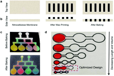 |
| | Fig. 1 Paper-based microfluidics. (a–b) Schematics of the working principle. (c) Demonstration of fluid flow using food color. (d) Optimization of the design for the DNA microarray study. | |
Smartphone readout setup
A portable optical sensing setup termed “FluoroZen” was made for detecting cancer biomarkers. The device was supported with excitation and emission filters operating within the 520–575 nm wavelength range to gather, collimate, and disperse light. Green LED light was used to project through the excitation filter inclined at 30° and stationed at a 35 mm working distance from the sample area. The sample area was illuminated at 90° along the light collection axis visualized through the emitter filter and images were captured by the smartphone placed on the top. In order to block external light and limit diffraction, the entire device was printed black. All the images in this study were acquired using the built-in camera of a smartphone (8-megapixel, iPhone 6). ImageJ software was used to deduce the RGB (red, green, blue) pixel value corresponding to the intensities retrieved from the image of the sample spot area. As our operating filters lie within the visible spectrum of the 400–700 nm regime, we evaluated the auto-fluorescence of FluoroZen by introducing the Cy3-dye on wax printed and baked iconic images, and adding orange colored food dye on a tiger imprint. Furthermore, LSU TIGER labelled with different colored letters was also printed to find the color with maximum auto-fluorescence. The Limit-of-Detection (LOD) of the device was estimated from image sets of arrays with various concentrations of Cy3-DNA oligonucleotide probes from 0 to 10 μM made by serial dilution with 3× SSC buffer and a control background (just 3× SSC buffer). The experiment was performed in triplicate for each set.
DNA hybridization assay
The utility of FluoroZen as a proof-of-concept platform for optical sensing applications was demonstrated by the DNA microarray (or DNA hybridization) experiment for the detection of breast cancer specific gene expression (BRCA1). 20 bp short oligonucleotide primers specific to Exon 11 of BRCA1 were used in our experiments. The different DNAs are labelled as probe DNA (T); target DNA (perfectly matched oligonucleotide (BRCA1(+))); non-cDNA (as negative control (BRCA1(−))); and 2-base pair mismatched DNA (for specificity (BRCA1(Mis))). Except the probe DNA (hereafter called “DNA-1”), all the remaining DNAs were conjugated with the Cy3 dye (hereafter called “DNA-2”). The working concentration of the probe DNA was 10 μM prepared from a 100 μM stock concentration by dilution with 3× SSC buffer. The DNA hybridization assay involved four main steps: (i) loading DNA-1, (ii) blocking, (iii) loading DNA-2, and (iv) washing. First, 1 μL of DNA-1 was dropped into the inlet zone with ∼25 seconds wait time until it reached the RZ (Reaction Zone at the middle circle). Second, 1% BSA/PBS was added for blocking the unbound DNA and left approximately for 15 minutes until dry. Third, 1 μL of DNA-2 was dropped from the same inlet with ∼60 seconds wait time until it reached the RZ for hybridization. Finally, 3 μL of 1% SDS was added slowly for washing and removing the unhybridized DNAs until it reached the end of the channel. The buffer was heated at 37 °C prior to use to avoid SDS precipitation. Each set of experiments took nearly 20 minutes and 3 sets of experiments were performed for each pair. The experiments were performed with minimal light exposure to avoid photobleaching. Images were captured immediately from FluoroZen by using an Apple iPhone 6 by placing the completely dried test run paper on the glass slide chamber, followed by image analysis using the ImageJ software as mentioned previously.
Results and discussion
Paper microfluidics
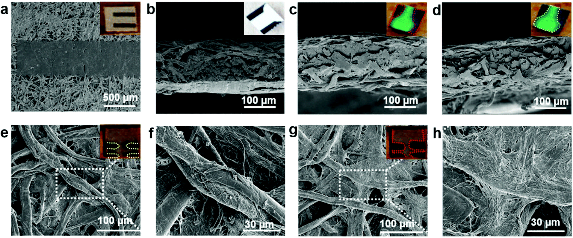
The nature of guided capillary flow in paper microfluidics was demonstrated by introducing different colored food dyes into individual channels before and after baking as shown in Fig. 1c. Upon baking, the molten wax penetrated into the paper creating a confined channel for guided flow of the individual colors orange, red, green, and blue, respectively, while for non-baked channels the colors merged and smeared all over. The acquired SEM images in top (Fig. 2a), and cross-sectional views (Fig. 2b) showed a wax print block on NC paper, wherein the cellulose fibers remained intact and unchanged. Fig. 2c and d show that adding a food dye did not alter the fiber properties. But in the case of baked channels (Fig. 2e and f), the molten wax created hydrophobic barriers and the fibers were conjoined, while fibers were disjoined in the regions where the wax was absent, indicating a hydrophilic region. μPADs are built on the concept of the isotropic process and since every printing and baking system has its own settings there is a limit in the resolution that can be obtained from the system.49 Hence, in order to overcome this ambiguity, all the parameter settings (thickness and porosity of the paper, orientation of fibers, line width, temperature and time of baking) should be consistent throughout the experimentation. A similar study established by George Whiteside's group in understanding wax printing before and after baking was adapted to understand our settings and deduce a mathematical expression based on our system.50 Single lines with nominal widths from 100 to 450 μm were printed and the degree of spreading of wax in paper was assessed after baking. The linear fit yielded Wb = 1.01Wp + 120, R2 = 0.99, where Wb = barrier width, and Wp = printed width (Fig. S1†). Two lines with nominal widths from 20 to 350 μm were printed to evaluate the minimum space that can be created using two channels with both white and black backgrounds. The linear fit for the white background yielded Sb = 0.95Sp − 65, R2 = 0.99 (Sb = barrier space, Sp = printed space) (Fig. S2†). The linear fit for the black background yielded Sb (black BG) = 0.92Sp (black BG) − 77, R2 = 0.99 (Sb (black BG) = barrier space created with the black background, Sp (black BG) = printed space created with the black background) (Fig. S3†). Although there is only a slight difference, in the c-intercept, this value is very important to create precise channels. The hydrophilic and hydrophobic boundaries on the paper are not very sharp which could be resolved by printing patterns on both sides of the paper. Furthermore, these equations could help predict the final width of hydrophobic barriers and channels and ease the design procedure. For biological studies, controlled fluid flow is important for effective substrate–analyte interactions. For example, in a recent study, wax pillars were made to produce delay barriers to improve the performance and sensitivity of lateral flow assays (LFA). The wax fabricated pillars were further applied for the detection of Human Immunoglobin G (HIgG) and the results showed three times better sensitivity in comparison with the conventional LFA devices.51 Therefore, in the present study, an open channel design for conducting the DNA hybridization study was established by optimizing the volume/area proportion. For the optimized design shown in Fig. 1d, it took ∼25 seconds for 1 μL of liquid to reach the second reservoir. The diameter of each of the reservoirs was 3 mm, length 15 mm, and width 1 mm (Fig. S4†). This volume/area proportion and the time lapse parameter are very critical for effective hybridization of DNA-1 with DNA-2. This is true for our DNA samples suspended in 3× SSC buffer and it might differ based on the viscosity of other samples. Furthermore, this might also depend on the pore size and surface roughness of the NC paper used.38 Additionally, this design parameter is particularly important as precise sample dilution is critical to achieve chemical reactions in biological assays. We demonstrated this using a paper dilution circuit that mixes equal volumes of 10 μM Cy3-DNA and 3× SSC buffer and allows control over the dilution factor based on the channel design. This dilution factor is dependent on the relative flow rates or the fluidic “resistances” of the two fluids and hence can differ with the fluids used.52 The concentration of Cy3-DNA relatively decreased from 10 μM to 2.5 μM (Fig. S5†). Hence, design of the channel and the working concentration of the DNAs is important for effective hybridization of targets with their counter probes. The importance of the design parameters in fluid flow in paper microfluidics is shown in Fig. S6†.
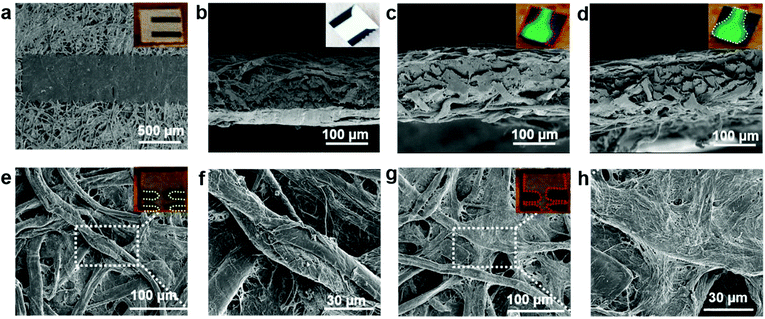 |
| | Fig. 2 SEM images. (a–b) After wax printing (as shown in the inset). (a) Top view. (b) Cross-sectional view. (c–d) After wax printing and adding dye to the channel. (c) Cross-sectional view of the red highlighted region. (d) Cross-sectional view of the yellow highlighted region. (e–h) After baking (as shown in the inset). (e–f) Hydrophobic barriers created as fibers are conjoined. (g–h) Hydrophilic red highlighted region as fibers are disjoined. | |
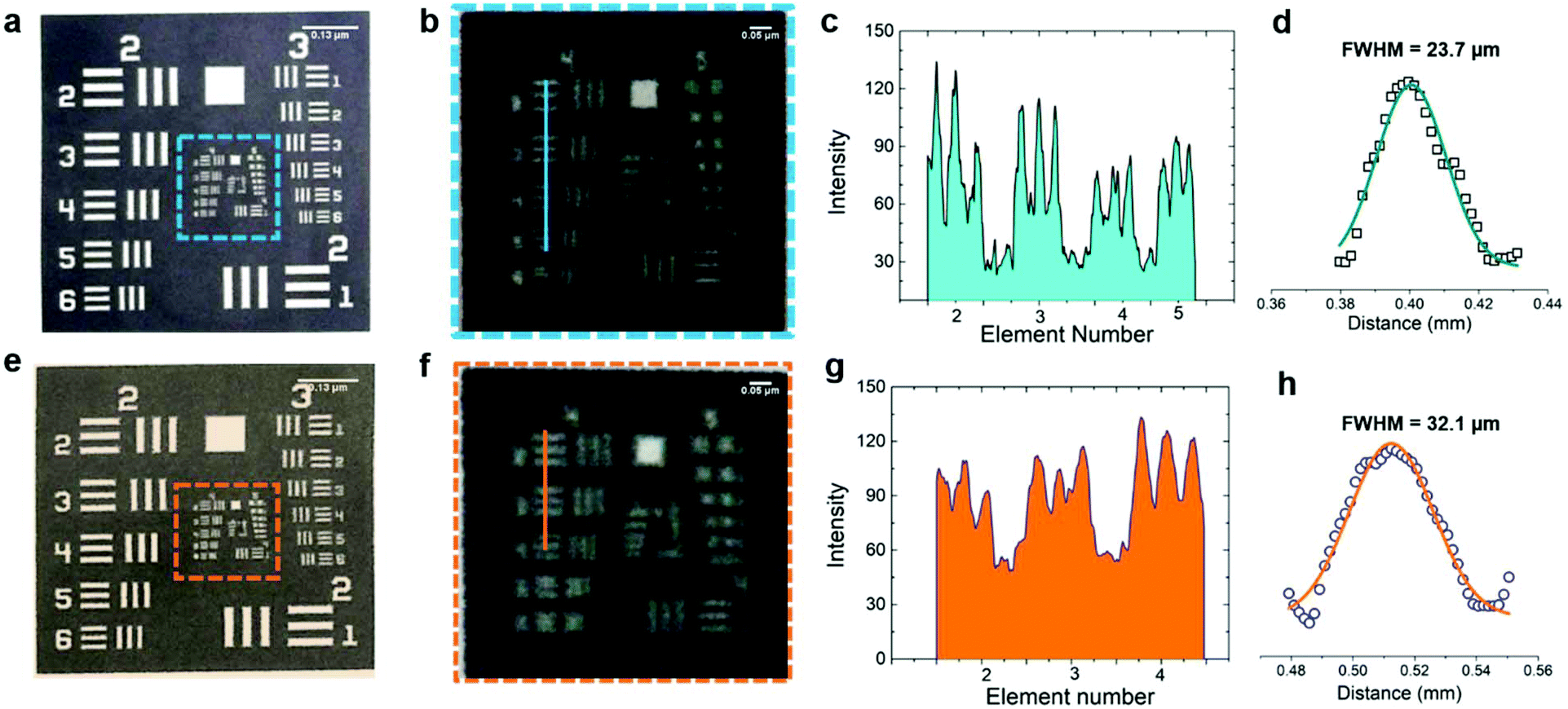
The resolution of our printing and baking system was obtained using a standard USAF Resolving Power Test Target 1951. From the image in Fig. 3a, it is observed that our system is capable of resolving 23.7 μm line pairs (Group 4, Element 5) for the blue highlighted region (from 3 × 3 inches2 image area). Fig. 3c shows the cross-sectional intensity profile and Fig. 3d shows the Full Width Half Maxima (FWHM) extracted from Fig. 3c using ImageJ. For the 2 × 2 inches2 image area, the resolution was found to be 32.1 μm (Group 4, Element 4) for the orange highlighted region. Fig. 3g shows the cross-sectional intensity profile and Fig. 3h shows the FWHM extracted from Fig. 3g using ImageJ.
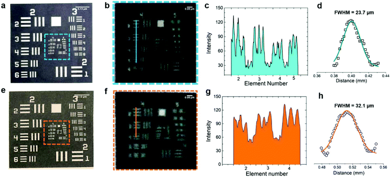 |
| | Fig. 3 Resolution of our printing and baking system using a standard USAF Resolving Power Test Target 1951. (a) 3 × 3 inches2 image area after printing. (b) 20 × 20 mm2 blue dotted region of the test target after baking. (c) Cross-sectional profile of Group 4, Element 5, of the resolution target, blue line in (b). (d) FWHM of (c). (e) 2 × 2 inches2 image area after printing. (f) 15 × 15 mm2 orange dotted region after baking. (g) Cross-sectional profile of Group 4, Element 4, of the resolution target, orange line in (b). (h) FWHM of (g). | |
Smartphone readout setup
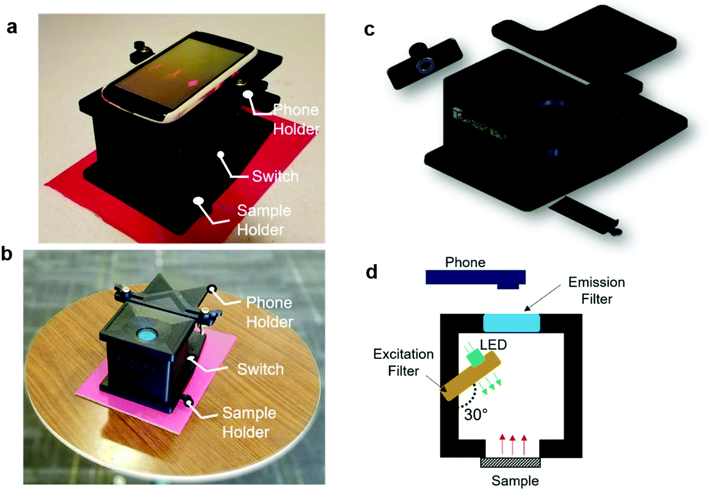
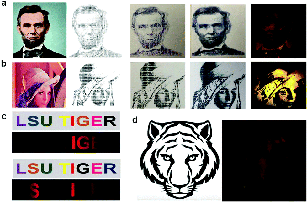
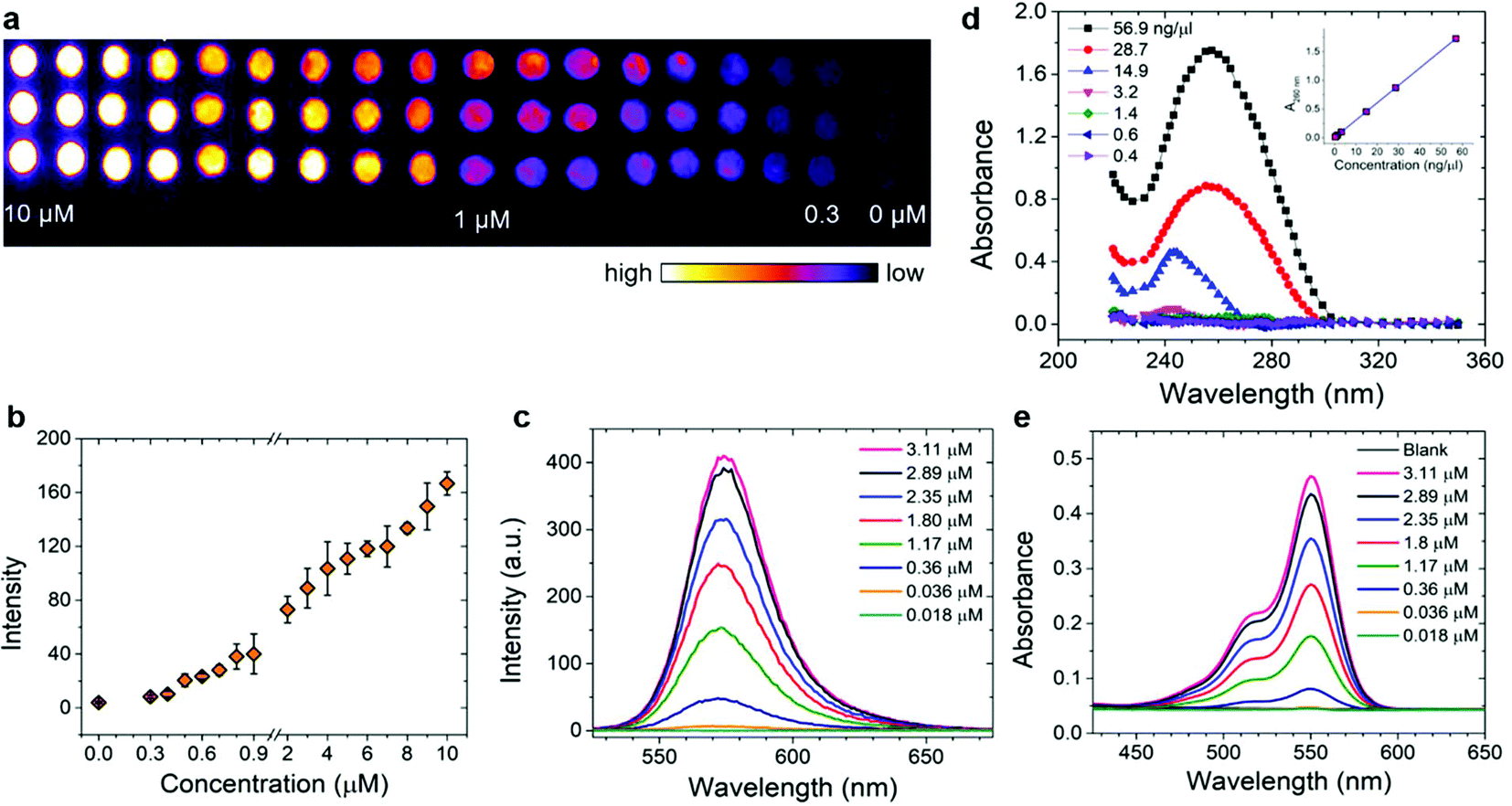
The image of the smartphone based portable optical sensing platform “FluoroZen” is shown in Fig. 4a (side view) and 4b (top view). Fig. 4c shows the different parts and the assembly of the device (image from SolidWorks2016). The schematic diagram in Fig. 4d shows the working principle of FluoroZen. When a sample (containing fluorophores) is illuminated with an LED source, the lower energy light emitted at a longer wavelength can be visualized by an emission filter by the naked eye and can also be captured by the CCD camera of mobile devices. This is similar to a conventional fluorescence microscope, except that it has an interference filter that blocks the unwanted wavelength and efficiently reflects a shorter wavelength and projects only the desired band of longer wavelength light.53 Although this provides an advantage of multi-modality imaging it increases the cost. FluoroZen, on the other hand, has easy insertion/removal supports to change filter lenses making it both portable and affordable for POCT. The fluorescence properties of the device were tested by converting iconic photographs into grayscale text images, followed by printing and baking to impose a facial channel on the NC paper. Fig. 5a & b show the procedure as well as the final captured image from FluoroZen upon introduction of the Cy3-dye. The bright visible “saffron” color emitted from Cy3 (λemission ≈ 554 nm) confirms the device capability to detect the spectrum within the filter range of 525–565 nm. Hence, DNA-2 used for our hybridization assay was tagged with Cy3. In order to test whether colored wax would emit fluorescence, the auto-fluorescence properties of the microfluidic device were evaluated by printing each letter of “LSU TIGER” using purple, blue, green, red, yellow, orange, black, and pink colors, respectively. The image captured using FluoroZen revealed that the maximum autofluorescence was displayed by red colored wax and the least was displayed by green colored wax (red is followed by pink, orange, and yellow colored wax). The colors whose spectra were closer to the filter spectrum displayed a higher intensity and hence were visible to the naked eye, while the remaining were not visible. The colors for each letter were swapped to confirm the auto-fluorescence properties (Fig. 5c). The auto-fluorescence properties evaluated by adding orange dye onto a Tiger imprint reconfirm this as shown in Fig. 5d. In order to avoid the discrepancy of auto-fluorescence, the optimized channel for the DNA hybridization assay was printed in black (as shown in Fig. 1c). In order to find the detection limit and dynamic range of the paper microfluidics based detection system, the Cy3-dye was spotted on the paper as shown in the set of images (red channel of the image) in Fig. 6a. The intensity of the spot decreases with the decrease in the concentration such that the fluorescence signals up to a concentration of 0.3 μM could be detected. Fig. 6b shows that the fluorescence intensity is linear over at least two-orders of magnitude with the dynamic range from 0.1 μM to 10 μM. The LOD was calculated from the limit of blank (LOB) as LOD = LOB + 1.645 × σsample with lowest concentration, where σ = standard deviation, LOB = mean of blank + 1.645 × σblank. The LOD was calculated to be 0.4 μM corresponding to 400 fmol of dye per zone spotted on the paper. Furthermore, the results were compared with spectroscopy-based measurements obtained from Cy3, DNA, and Cy3 coupled with DNA samples. The absorbance of the DNA increased with the concentration and the peak was found to be at ∼λ = 260 nm. The absorbance method of detection is reliable up to ∼0.6 ng μL−1 (Fig. 6d). The absorbance and emission of the Cy3 are shown in Fig. 6e and c, respectively. The detection limit of fluorescence spectroscopy (Fig. 6c) was found to be 10 times lower than that of the fluorescence imaging based quantification (∼0.04 μM or 40 fmol). The combined absorbance and fluorescence emission data of the dye (Fig. 6c, e, and Fig. S7†) can be utilized to calculate the ratio of the number of DNA to dye, which was found to be 8.55 DNA/dye using the following relationship:| | 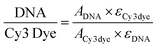 | (1) |
where A = absorbance and ε = extinction coefficient.
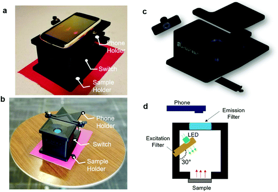 |
| | Fig. 4 Optical setup (a) showing the smartphone and the 3D printed platform and (b) optical image of the assembled 3D printed platform. (c) Exploded view of the 3D printed platform showing different components. (d) Schematics of the optical elements of FluoroZen. | |
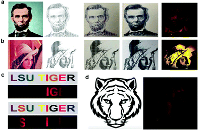 |
| | Fig. 5 Evaluating the fluorescence properties of FluoroZen. (a) Image of Abraham Lincoln and (b) standard test image of Lena Soderberg. Left to right: Original image, recreation of the image with text in black, after wax printing, after baking, and fluorescence imaging using FluoroZen. (c) Testing the auto-fluorescence properties of the colored wax by printing “LSU TIGER” (top image) and swapping colors (bottom image) for comparison. (d) Fluorescence image of a microfluidic channel created from the image of a tiger. | |
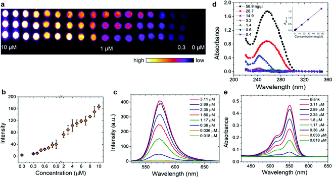 |
| | Fig. 6 Limit of detection and dynamic range of the paper-based microarray. (a) Image sets of arrays with various concentrations of Cy3-DNA oligonucleotide probes from 0 to 10 μM and the background (red channel). (b) Variation of the fluorescence intensity (RGB pixel value) with the concentration of Cy3 in (a). (c) Fluorescence spectrum of Cy3 at different concentrations. (d) Absorbance of DNA oligonucleotides at different concentrations (inset showing the linear calibration curve for absorbance versus concentration). (e) Absorbance spectrum of Cy3 at the concentrations shown in (c). | |
DNA hybridization assay
The utility of the device for POC sensing was demonstrated by the DNA hybridization assay.
The optical sensing was based on the signal detection upon interactive binding of DNA-1 with DNA-2. The assay was conducted on our optimized channel design as shown in Fig. 7a wherein image set P (Positive) displayed higher fluorescence in comparison with set M (Mismatch), while set N (Negative) displayed little-to-no fluorescence. Fig. 7b shows the primers for T, BRCA(+), BRCA(−), and BRCA(Mis). The CCD camera of a smartphone was used to acquire the images. The images are then imported to the ImageJ software to extract the red (R), green (G), and blue (B) pixel values. The images are converted into 8-bit greyscale images that have 28 or 256 intensity graduations in terms of pixels. The pixel with an intensity of 0 is black, while 255-pixel intensity is white and the remaining lies between the shades of grey. The ImageJ software enables separation of pixels which fall within a desired range of intensity values (Region of Interest (ROI)) from those which do not, by thresholding (or segmentation). Thresholding is an effective method to measure complex or nonuniform features in an image. The Analyze command in the ImageJ software is used to count and measure the thresholded images. The Analyze menu also contains a Set Measurements dialog box, wherein the user can obtain information about the area of selection in pixels, mean gray value, integrated density etc. Fig. 7c shows a bar chart for the corresponding fluorescence intensity acquired from the device upon DNA hybridization. The positive sequences (∼3.48 × 10⁴) had the highest fluorescence intensity in comparison with mismatched (∼2.49 × 10⁴) and negative (∼1.72 × 10⁴) sequences. The intensity from the negative sequences was ∼50% less in comparison with that of the positive sequences. The low intensity peaks from the negative sequences might be a result of the adsorption of residual Cy3 to the NC paper. This optical detection approach provided a semi-quantitative ‘YES/NO’ response type detection system. The advantage of this approach is that in the microfluidic based approach the hybridization completed in 1 minute compared to the long lag time of a few hours for the conventional hybridization based assays. Furthermore, the use of paper makes it more accessible, affordable, and eco-friendly. The number of DNA copies involved during the hybridization was also calculated based on the assumption that the average weight of 1 base pair (bp) is ≈660 g mol−1 using the following formulas:
| |  | (2) |
| |  | (3) |
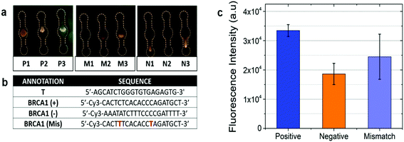 |
| | Fig. 7 DNA microarray experiment using paper microfluidics. (a) Fluorescence intensity w.r.t cell. (b) DNA sequence list. (c) Bar chart of normalized intensity from the highlighted region for different sequences. | |
The total number of DNA copies in 100 μM stock solution was calculated to be 4.705 × 10¹⁶ copies in 1.65 mL, where the mass of our DNA was 1030.9 μg and the total number of DNA molecules with 20 bp length was found to be 2.191 × 10⁻²⁰ g. For 10 μM working solution and 1 μL working volume used in our assay, the initial copy number was found to be 2.85 × 10¹³ DNA copies. Hence, it can be concluded that a minimum number of 11 log![[thin space (1/6-em)]](https://www.rsc.org/images/entities/char_2009.gif) 10 DNA copies is required for detecting BRCA-1 genes using the paper microfluidic smartphone readout setup corresponding to a 0.4 μM LOD with a dilution factor of 250.
10 DNA copies is required for detecting BRCA-1 genes using the paper microfluidic smartphone readout setup corresponding to a 0.4 μM LOD with a dilution factor of 250.
Conclusion
In summary, a portable optical sensing platform named ‘FluoroZen’ was developed and demonstrated for detection of BRCA-1 gene breast cancer specific disease biomarkers. We presented the fabrication of μPADS on NC filter paper by the wax-printing and baking technique.
Based on the standard USAF Resolving Power Test Target 1951, our system is capable of resolving 23.7 μm line pairs. We also deduced three simple equations to predict the final width of the printed channels and the hydrophobic barriers, and the space between the channels and lines and ease the design process. Furthermore, a DNA hybridization assay based on paper microfluidics was developed to allow the optical detection of the fluorescent labelled oligonucleotide spots with a semi-quantitative ‘YES/NO’ response within 20 minutes. Based on the paper-based microarray assay, the LOD of the device was identified to be 400 fmol, with a detection sensitivity of around 11 log10 DNA copies for BRCA-1 genes. In addition, μPADS systems are inexpensive, easy to use, and capable of scaling-up. Combining the DNA microarray assay based on μPADS with a smartphone readout system is a promising approach to achieve rapid and valuable prognostic information for possible metastatic risks. We envisage extensive use of “FluoroZen” to explore other bioanalytical assays for clinical diagnosis in resource limited settings.
Conflicts of interest
There are no conflicts to declare.
Acknowledgements
We acknowledge the support from Louisiana Board of Regents Support Fund (Contract Number: LEQSF(2017-20)-RD-A-04 and LEQSF(2017-18)-ENH-TR-08) and the National Science Foundation (NSF Award Number: 1660233). Scanning Electron Microscopy (SEM) was performed at the Shared Instrumentation Facility (SIF) at Louisiana State University.
References
- J. L. Shaw, Pract. Lab. Med., 2016, 4, 22–29 CrossRef PubMed.
- R. Suebsing, J. Kampeera, B. Tookdee, B. Withyachumnarnkul, W. Turner and W. Kiatpathomchai, Lett. Appl. Microbiol., 2013, 57, 317–324 CAS.
- R. G. Norkus, J. Maurer, N. A. Schultz, J. D. Stuart, G. A. Robbins and R. D. Bristol, Chemosphere, 1996, 33, 421–436 CrossRef CAS PubMed.
- M. R. Gartia, B. Braunschweig, T.-W. Chang, P. Moinzadeh, B. S. Minsker, G. Agha, A. Wieckowski, L. L. Keefer and G. L. Liu, J. Environ. Monit., 2012, 14, 3068–3075 RSC.
- A. Litster, B. Pressler, A. Volpe and E. Dubovi, Vet. J., 2012, 193, 363–366 CrossRef CAS PubMed.
- G. Bansal, W. Zhou, P. J. Barlow, P. S. Joshi, H. L. Lo and Y. K. Chung, Crit. Rev. Food Sci. Nutr., 2010, 50, 503–514 CrossRef CAS PubMed.
- A. Priye, S. W. Bird, Y. K. Light, C. S. Ball, O. A. Negrete and R. J. Meagher, Sci. Rep., 2017, 7, 44778 CrossRef CAS PubMed.
- A. Larsson, R. Greig-Pylypczuk and A. Huisman, Upsala J. Med. Sci., 2015, 120, 1–10 CrossRef PubMed.
- X. Wang, M. R. Gartia, J. Jiang, T.-W. Chang, J. Qian, Y. Liu, X. Liu and G. L. Liu, Sens. Actuators, B, 2015, 209, 677–685 CrossRef CAS.
- J. Matthews, R. Kulkarni, M. Gerla and T. Massey, Mobile Netw. Appl., 2012, 17, 178–191 CrossRef.
- K. Mahato, A. Prasad, P. Maurya and P. Chandra, J. Anal. Bioanal. Technol., 2016, 7, e125 Search PubMed.
- P. B. Luppa, C. Müller, A. Schlichtiger and H. Schlebusch, TrAC, Trends Anal. Chem., 2011, 30, 887–898 CrossRef CAS.
- A. St John and C. P. Price, Clin. Biochem. Rev., 2014, 35, 155 Search PubMed.
- K. D. Long, H. Yu and B. T. Cunningham, Biomed. Opt. Express, 2014, 5, 3792–3806 CrossRef CAS PubMed.
-
K. D. Long, H. Yu and B. T. Cunningham, Next-Generation Spectroscopic Technologies VIII. Proc. Bellingham, SPIE, WA, 2015, vol. 98227, p. 94820J Search PubMed.
-
G. Comtois, J. I. Salisbury and Y. Sun, Bioengineering Conference (NEBEC), 2012 38th Annual Northeast, PA, 2012, pp. 69–70.
- C.-C. Huang, P.-Y. Lee, P.-Y. Chen and T.-Y. Liu, IEEE Trans. Ultrason. Ferroelectr. Freq. Control., 2012, 59, 182–188 Search PubMed.
- D. N. Breslauer, R. N. Maamari, N. A. Switz, W. A. Lam and D. A. Fletcher, PLoS One, 2009, 4, e6320 CrossRef PubMed.
- Q. Wei, H. Qi, W. Luo, D. Tseng, S. J. Ki, Z. Wan, Z. n. Göröcs, L. A. Bentolila, T.-T. Wu and R. Sun, ACS Nano, 2013, 7, 9147–9155 CrossRef CAS PubMed.
- D. Gallegos, K. D. Long, H. Yu, P. P. Clark, Y. Lin, S. George, P. Nath and B. T. Cunningham, Lab Chip, 2013, 13, 2124–2132 RSC.
- A. W. Martinez, S. T. Phillips, E. Carrilho, S. W. Thomas III, H. Sindi and G. M. Whitesides, Anal. Chem., 2008, 80, 3699–3707 CrossRef CAS PubMed.
- A. K. Ellerbee, S. T. Phillips, A. C. Siegel, K. A. Mirica, A. W. Martinez, P. Striehl, N. Jain, M. Prentiss and G. M. Whitesides, Anal. Chem., 2009, 81, 8447–8452 CrossRef CAS PubMed.
- K. Nishi, S.-I. Isobe, Y. Zhu and R. Kiyama, Sensors, 2015, 15, 25831–25867 CrossRef CAS PubMed.
- A. Abbaspour, M. A. Mehrgardi, A. Noori, M. A. Kamyabi, A. Khalafi-Nezhad and M. N. S. Rad, Sens. Actuators, B, 2006, 113, 857–865 CrossRef CAS.
- M. Pollice and H. Yang, Clin. Lab. Med., 1985, 5, 463–473 CrossRef CAS PubMed.
- A. Abe, M. Kitagawa, Y. Ikuta, S. Miyakoshi, H. Danbara, N. Kashiwagi and F. Obata, J. Immunol. Methods, 1992, 154, 205–210 CrossRef CAS PubMed.
- R. P. Auburn, D. P. Kreil, L. A. Meadows, B. Fischer, S. S. Matilla and S. Russell, Trends Biotechnol., 2005, 23, 374–379 CrossRef CAS PubMed.
- P. Serra, M. Colina, J. M. Fernández-Pradas, L. Sevilla and J. L. Morenza, Appl. Phys. Lett., 2004, 85, 1639–1641 CrossRef CAS.
- B. Lee, A. Tajima, J. Kim, Y. Yamagata and T. Nagamune, Biotechnol. Bioprocess Eng., 2010, 15, 145–151 CrossRef CAS.
- C. Lausted, T. Dahl, C. Warren, K. King, K. Smith, M. Johnson, R. Saleem, J. Aitchison, L. Hood and S. R. Lasky, Genome Biol., 2004, 5, R58 CrossRef PubMed.
- D. Zhang, J. Lee, M. B. Sun, Y. Pei, J. Chu, M. U. Gillette, T. M. Fan and K. A. Kilian, ACS Cent. Sci., 2017, 3(5), 381–393 CrossRef CAS PubMed.
- P. C. Mathias, S. I. Jones, H.-Y. Wu, F. Yang, N. Ganesh, D. O. Gonzalez, G. Bollero, L. O. Vodkin and B. T. Cunningham, Anal. Chem., 2010, 82, 6854–6861 CrossRef CAS PubMed.
- C. D. Chin, V. Linder and S. K. Sia, Lab Chip, 2007, 7, 41–57 RSC.
- J. Wang, Biosens. Bioelectron., 2006, 21, 1887–1892 CrossRef CAS PubMed.
-
A. C. Siegel, S. T. Phillips, M. D. Dickey, D. Rozkiewicz, B. Wiley, G. M. Whitesides and A. W. Martinez, U.S. Pat., 8921118, 2014 Search PubMed.
- A. W. Martinez, S. T. Phillips, M. J. Butte and G. M. Whitesides, Angew. Chem., Int. Ed., 2007, 46, 1318–1320 CrossRef CAS PubMed.
- A. W. Martinez, S. T. Phillips, G. M. Whitesides and E. Carrilho, Anal. Chem., 2010, 82, 3–10 CrossRef CAS PubMed.
- A. C. Glavan, J. Niu, Z. Chen, F. Güder, C.-M. Cheng, D. Liu and G. M. Whitesides, Anal. Chem., 2015, 88, 725–731 CrossRef PubMed.
- G. Luka, E. Nowak, J. Kawchuk, M. Hoorfar and H. Najjaran, R. Soc. Open Sci., 2017, 4, 171025 CrossRef CAS PubMed.
- F. B. Myers and L. P. Lee, Lab Chip, 2008, 8, 2015–2031 RSC.
- B. Berg, B. Cortazar, D. Tseng, H. Ozkan, S. Feng, Q. Wei, R. Y.-L. Chan, J. Burbano, Q. Farooqui and M. Lewinski, ACS Nano, 2015, 9, 7857–7866 CrossRef CAS PubMed.
- Y. Wang, M. M. Zeinhom, M. Yang, R. Sun, S. Wang, J. N. Smith, C. Timchalk, L. Li, Y. Lin and D. Du, Anal. Chem., 2017, 89, 9339–9346 CrossRef CAS PubMed.
- W. Chen, H. Yu, F. Sun, A. Ornob, R. Brisbin, A. Ganguli, V. Vemuri, P. Strzebonski, G. Cui and K. J. Allen, Anal. Chem., 2017, 89, 11219–11226 CrossRef CAS PubMed.
- X. Li, F. Yang, J. X. Wong and H.-Z. Yu, Anal. Chem., 2017, 89, 8908–8916 CrossRef CAS PubMed.
-
A. Venkatesh, T. van Oordt, E. M. Schneider, R. Zengerle, F. von Stetten, J. H. Luong and S. K. Vashist, Biosensors and Biodetection: Methods and Protocols Volume 1: Optical-Based Detectors, 2017, pp. 343–356 Search PubMed.
- F. Wang, Y. Lu, J. Yang, Y. Chen, W. Jing, L. He and Y. Liu, Analyst, 2017, 142, 3177–3182 RSC.
- M. Lu, S. D. Conzen, C. N. Cole and B. A. Arrick, Cancer Res., 1996, 56, 4578–4581 CAS.
- A. Reinhartz, S. Alajem, A. Samson and M. Herzberg, Gene, 1993, 136, 221–226 CrossRef CAS PubMed.
- M. M. Thuo, R. V. Martinez, W.-J. Lan, X. Liu, J. Barber, M. B. Atkinson, D. Bandarage, J.-F. Bloch and G. M. Whitesides, Chem. Mater., 2014, 26, 4230–4237 CrossRef CAS.
- E. Carrilho, A. W. Martinez and G. M. Whitesides, Anal. Chem., 2009, 81, 7091–7095 CrossRef CAS PubMed.
- L. Rivas, M. Medina-Sánchez, A. de la Escosura-Muñiz and A. Merkoçi, Lab Chip, 2014, 14, 4406–4414 RSC.
- J. L. Osborn, B. Lutz, E. Fu, P. Kauffman, D. Y. Stevens and P. Yager, Lab Chip, 2010, 10, 2659–2665 RSC.
- C. M. Brown, J. Cell Sci., 2007, 120, 1703–1705 CrossRef CAS PubMed.
Footnote |
| † Electronic supplementary information (ESI) available. See DOI: 10.1039/c8an01020j |
|
| This journal is © The Royal Society of Chemistry 2019 |
Click here to see how this site uses Cookies. View our privacy policy here. 
 ,
Syed Mohammad Abid
Hasan
,
Syed Mohammad Abid
Hasan