Impact of the use of sterically congested Ir(III) complexes on the performance of light-emitting electrochemical cells†‡
Claus
Hierlinger
ab,
Elzbieta
Trzop
 c,
Loïc
Toupet
c,
Jorge
Ávila
d,
Maria-Grazia
La-Placa
d,
Henk J.
Bolink
c,
Loïc
Toupet
c,
Jorge
Ávila
d,
Maria-Grazia
La-Placa
d,
Henk J.
Bolink
 d,
Véronique
Guerchais
 *a and
Eli
Zysman-Colman
 *b
*b
aUniv Rennes, CNRS, ISCR (Institut des Sciences Chimiques de Rennes) – UMR 6226, F-35000 Rennes, France. E-mail: veronique.guerchais@univ-rennes1.fr
bOrganic Semiconductor Centre, EaStCHEM School of Chemistry, University of St Andrews, St Andrews, Fife KY16 9ST, UK. E-mail: eli.zysman-colman@st-andrews.ac.uk; Web: http://www.zysman-colman.com
cUniv Rennes, CNRS, IPR (Institut de Physique de Rennes) – UMR 6251, F-35000 Rennes, France
dInstituto de Ciencia Molecular, Universidad de Valencia, C/J. Beltran 2, 46980 Paterna, Spain. E-mail: Mg.Laplaca@uv.es
First published on 4th April 2018
Abstract
The synthesis, structural and optoelectronic characterization of a family of sterically congested cyclometalated cationic Ir(III) complexes of the form [Ir(C^N)2(dtBubpy)]PF6 (with dtBubpy = 4,4′-di-tert-butyl-2,2′-bipyridine and C^N = a cyclometalating ligand decorated at the 4-position of the pyridine ring and/or the 3-position of the phenyl ring with a range of sterically bulky substituents) are reported. This family of complexes is compared to the unsubstituted analogue complex R1 bearing 2-phenylpyridinato as cyclometalating ligand. The impact of sterically bulky substituents on the C^N ligands on both the solid state photophysics and light-emitting electrochemical cell (LEEC) device performance is investigated. X-ray diffraction analysis of complexes 1a, R2, 2a, and 1b show an increasing internuclear distance in the solid state, within these four complexes. Emission studies in solution and neat film show that the chosen substituents essentially do not impact the emission energy. The photoluminescence quantum yields (ΦPL) are in the same range (ΦPL ∼ 25–31%), except for 1b, which shows a lower ΦPL of 12%. All complexes exhibit similar monoexponential emission lifetimes in the submicrosecond regime. LEECs based on R1, 1a, 1b and R2 were fabricated, showing yellow luminescence and moderate efficiencies and lifetimes. The arguably best performing LEEC device, showing the highest luminance (737 cd m−2), current efficiency (7.4 cd A−1) and EQE (2.6%), employed emitter 1a.
Introduction
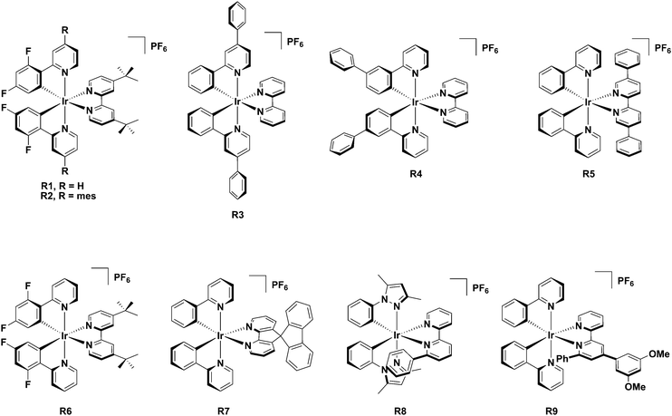
Iridium(III) complexes have a remarkable combination of photophysical properties,1 including high photoluminescence quantum yields, ΦPL, wide colour tunability, relatively short-lived phosphorescence lifetimes, τPL, that make them the go-to emitter class in solid-state electroluminescence (EL) devices, such as organic light emitting diodes (OLEDs)2 and in light emitting electrochemical cells (LEECs).3 LEECs possess a much simpler design, with fewer layers, compared to OLEDs,4 as they typically employ an ionic emissive material that is dually responsible for charge mobility and the emission of light within the device. The most popular and widely studied class of emitters for LEECs is the heteroleptic cationic Ir(III) complex of the form [Ir(C^N)2(N^N)]PF6 (C^N is a cyclometalating ligand, N^N is a diimine ancillary ligand).Unlike in OLEDs where the emissive compound is present in only small concentrations as a dopant within a higher bandgap host, in LEECs the emissive layer is frequently composed either of a homogenous layer of emitter molecules or the emitter is the major component within the layer. As a consequence, one issue that can limit device performance is excited state self-quenching during device operation.5 A strategy to circumvent this issue is to decorate the complexes with bulky, hydrophobic substituents that serve to increase the intermolecular distance while simultaneously hindering the disadvantageous attack of small molecules.6Chart 1 shows representative literature examples of iridium complexes (R1–R9) bearing bulky substituents that have been used as emitters in light-emitting electrochemical cells.
A successful molecular design that was applied to charge-neutral Ir(III) complexes for OLEDs was the incorporation of mesityl substituents at the C(4) position of the pyridyl ring of the ppy ligands in [Ir(dFmesppy)2(pic)] (dFmesppyH = 2-(4,6-difluorophenyl)-4-(mesityl)-pyridine and pic = picolinate). An increase in the photoluminescence quantum yield, ΦPL, was observed, which also translated into enhanced external quantum efficiencies of the OLED devices compared to that employing the well-known [Ir(dFppy)2(pic)], FIrpic (dFppyH = 2-(4,6-difluorophenyl)pyridine).7 The enhancement in EQE compared to the FIrpic-based devices was attributed to reduced concentration quenching and increased solubility in organic solvents and therefore better dispersion during the fabrication of the solution-processed device. Notably, the mesityl group adopts an orthogonal conformation relative to the pyridine ring, resulting in a disruption of the conjugation between these two aryl groups, minimizing the impact on the emission energy. Such an approach has been applied to cationic iridium complexes by us, where we have observed an enhancement of solution- and solid-state ΦPL compared to the non-decorated analog complex.8
A comparison of R1 and R2 of the form [Ir(C^N)2(dtBubpy)]PF6 (where C^N is ppy or mesppy for R1 and R2, respectively and dtBubpy is 4,4′-di-tert-butyl-2,2′-bipyridine) reveals the impact of the mesityl group on the photophysical properties in cationic complexes.8a In CH2Cl2, the same emission maximum (λPL = 577 nm) is observed for both complexes while the ΦPL is moderately enhanced for the mesitylated complex (ΦPL = 35 and 40% for R1 and R2, respectively). The LEECs fabricated with R1,8a showed a lifetime of t1/2 = >1300 h and an EQE of 2.5%. Surprisingly and in contrast to the above-mentioned impact of the mesityl group, for LEECs based on R2 there was a reduction in the device lifetime (t1/2 = 0.6 h) and EQE (1.4%) upon incorporation of the mesityl groups on the C^N ligands. However, with R2 faster response times could be achieved in devices compared to those based on R1, as the mesityl groups induce a more efficient electronic communication and recombination within the device, which results in faster turn-on times. The related complex [Ir(dPhPy)2(bpy)]PF6, R3 (where dPhPy is 2,4-diphenylpyridine and bpy is 2,2′-bipyridine) bears a phenyl group on the 4-position of the pyridine of the C^N ligand in lieu of a mesityl group and contains a bpy N^N ligand in lieu of the dtBubpy ligand.9 In CH2Cl2, complex R3 exhibits yellow phosphorescence (λem = 598 nm) with a ΦPL of 21%. A single-layer LEEC based on R3 containing a lithium salt additive showed improved device performance compared to the unsubstituted analogue. The device with R3 displayed a short response time (ton = 5 min), favorable lifetime (extrapolated lifetime calculated at 100 cd m−2, t1/2L100 of 3800 h), and a peak luminance of 5500 cd m−2 (with ton = 191 min, t1/2L100 = 4752 h and a peak luminance of 2753 cd m−2 for the unsubstituted analog). The authors ascribed the improved LEEC performance to the bulky, hydrophobic nature of the phenyl substituent, which they asserted impeded self-quenching pathways of the Ir(III) complex. Another analogous complex is [Ir(Phppy)2(bpy)]PF6, R4 (where Phppy is 2-([1,1′-biphenyl]-3-yl)pyridine), bearing a phenyl group trans to the Ir–CC^N bond. Complex R4 exhibits a yellow-orange emission with a ΦPL of 13% in CH2Cl2. LEECs based on R4 are likewise highly stable with t1/2 = 2800 h and also are very bright with a maximum luminance of 1024 cd m−2.10
The use of the sterically congested the dtBubpy in R611 coupled with dFppy ligands contributed to a record maximum external quantum efficiency in the LEEC of 15%,11a significantly higher than that reported for the LEECs with R1, with EQE values ranging from 0.6–5.0%.8a,12 LEECs fabricated with R512b incorporating a bulky ancillary ligand (5,5′-diphenyl-2,2′-bipyridine, dpbpy) showed long device lifetimes of 110 h (LEEC operating at 4 V), particularly compared to [Ir(ppy)2(dtBubpy)]PF6, R1 (1.3 h). Using R7,5 which contained the 4,5-diaza-9,9′-spirobifluorene ancillary ligand, resulted in LEECs with a maximum external quantum efficiencies of 7.1% at a device lifetimes of 12 h and luminance value of 52 cd m−2.
Very stable LEECs have been fabricated employing emissive complexes where there is a phenyl ring positioned adjacent to one of the coordinating nitrogen atoms of the ancillary ligand as exemplified in [Ir(dmppz)2(pbpy)]PF6, R8, (where dmppz is 3,5-dimethyl-1-phenylpyrazole and pbpy is 6-phenyl-2,2′-bipyridine).13 The phenyl ring of the pbpy forms a face-to-face π-stacking with the pyrazole unit of the C^N ligand, which insulates the complex from adventitious attack from small molecules.14 High stability LEECs were fabricated with the complex [Ir(ppy)2(Meppbpy)]PF6, R9, (where Meppbpy is 4-(3,5-dimethoxyphenyl)-6-phenyl-2,2′-bipyridine) with a device lifetime of over 950 h and high luminance and current efficiency (183 cd m−2 and 8.2 cd A−1, respectively).15 In the majority of cases, decorating the complex with bulky, hydrophobic substituents greatly improves the stability of LEECs.
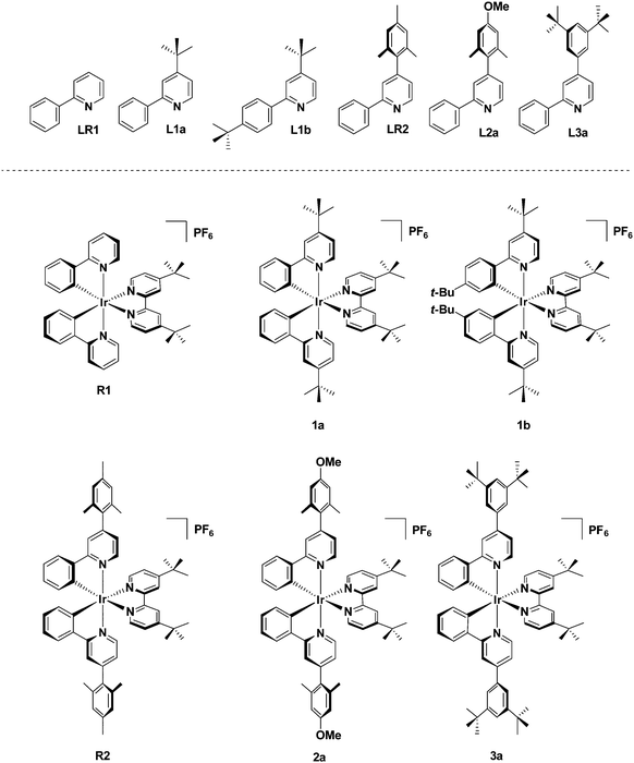
These previous findings prompted us to design a family of cationic Ir(III) complexes of the form [Ir(C^N)2(dtBubpy)]PF6 in which the sterics about the C^N ligands are systematically modified via a combination of decoration at the 4-position of the pyridine ring and/or the 3-position of the phenyl ring in order to ascertain how the steric requirements affect the photophysics of the complexes and the corresponding LEEC device performance (Fig. 1). Complexes R1 and R2 were included into this study to serve as references.
Results and discussion
Synthesis of the C^N ligands
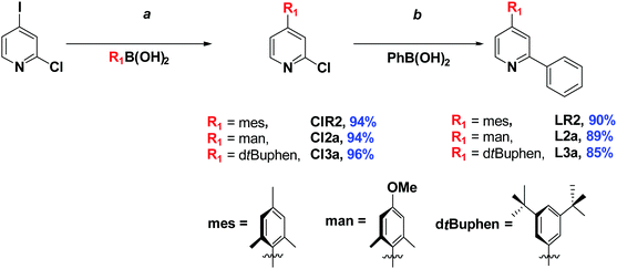
The family of substituted 2-phenylpyridine (ppyH) cyclometalating C^N ligands bearing R1 (at the 4-pyridine position) and R2 (at the 4-phenyl position) can be divided into two classes: 4-substituted 2-phenylpyridine derivatives L1a, LR1, L2a and L3a [with R1 = tert-butyl (tBu), mesityl (mes), manisyl (man) – 4-methoxy-2,6-dimethylphenyl, and 3,5-di-tert-butylphenyl (dtBuphen), respectively, and R2 = H], and the substituted arylpyridine L1b (where R1 = R2 = tert-butyl). The ligand LR1 is the unsubstituted ppyH (Fig. 1).Compounds L1a and L1b are accessible as colourless oils from 4-tert-butylpyridine via a Minisci reaction16 in moderate yields (45 and 46%, respectively), while LR1 was commercially available. For LR2, L2a and L3a, a two-step Suzuki–Miyaura cross-coupling strategy was adapted from 2-chloro-4-iodopyridine (Scheme 1).8c The mono-arylated 2-chloro-4-substituted compounds ClR2, Cl2a and Cl3a were isolated in excellent yields (94–96%) after purification by column chromatography. Key to the high yields is the use of excess R1B(OH)2, which led to easier purification of the intermediate 4-aryl-2-chloropyridines. A second Suzuki–Miyaura reaction with PhB(OH)2 afforded LR1, L2a and L3a in excellent yields (86–90%) (Scheme 1).
Synthesis of the Ir(III) complexes
The target complexes were synthesised via a two-step literature procedure (Scheme 2). The C^N ligands were each first reacted with IrCl3·6H2O to afford the corresponding [Ir(C^N)2Cl]2 dimers in excellent yields (79–89%).17 These intermediate dimers were then reacted with dtBubpy in the presence of AgPF6 to afford the desired heteroleptic complexes as yellow solids in generally excellent yields (79–92%) as their hexafluorophosphate salts.18 Through the systematic increase of steric bulk of the cyclometalated ligands, the corresponding [Ir(C^N)2Cl]2 dimers as well as the cationic complexes show increased solubility in organic solvents such as CH2Cl2, CHCl3 and MeCN compared to [Ir(ppy)2Cl]2 and the reference complex R1. Recrystallization from pentane/diethyl ether gave pure R1, whereas for the other complexes (1a, 1b, R2, 2a and 3a) column chromatography on silica (eluent: 5% MeOH in CH2Cl2) was required. Following chromatographic purification, a second anion exchange reaction with NH4PF6 was conducted to ensure that the sole counterion was PF6−.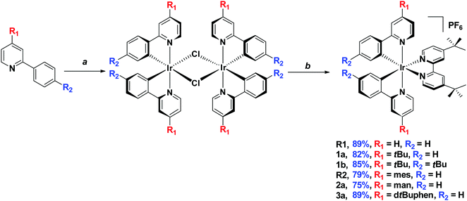 | ||
| Scheme 2 Synthesis of target complexes. aIrCl3·6H2O, 2-ethoxtyethanol/H2O (3/1), 125 °C, 24 h. b(1) 4,4′-di-tert-butyl-2,2′-bipyridine, AgPF6, 1,2-dichloroethane, 85 °C, 2 h. (2) r.t., 12 h. | ||
X-ray structural studies
Single crystals of sufficient quality of 1a, 1b, R2 and 2a were grown from CH2Cl2/Et2O. The determined space groups are P![[1 with combining macron]](https://www.rsc.org/images/entities/char_0031_0304.gif) (for 1a) and P21 (for 1b, R2 and 2a). The crystal structure of R2 has been previously reported; however, in the previous report the crystallization conditions were different.8a The crystal structure of 1a, 1b, R2 and 2a are presented in Fig. 2.
(for 1a) and P21 (for 1b, R2 and 2a). The crystal structure of R2 has been previously reported; however, in the previous report the crystallization conditions were different.8a The crystal structure of 1a, 1b, R2 and 2a are presented in Fig. 2.
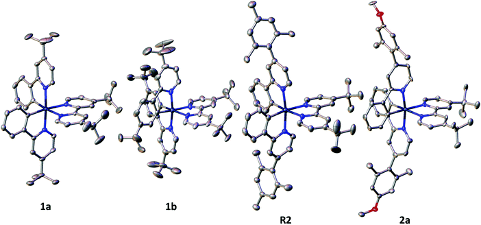 | ||
| Fig. 2 Representation of the crystal structure of 1a, 1b, R2 and 2a. The hydrogen atoms, solvent molecules, minor disorder, as well as the counter ion PF6− are omitted for clarity. | ||
All complexes show the expected distorted octahedral geometry around the Ir centre with the pyridyl units of the C^N ligands mutually trans to each other, as is commonly seen in other cationic Ir(III) complexes of the form [Ir(C^N)2(N^N)]PF6.1c,19 The bond lengths and bond angles are as expected for this class of iridium complex. The torsion angles based on the angle between the planes of the R1 aryl and the pyridine rings of the two C^N ligands in R2 are 78.32° and 88.70° and in 2a are 81.58° and 89.97°, which are similar to those previously reported for arylated C^N ligands in charged complexes,8b–d but are notably larger to those found in R3 for which an average torsion angle of 26° between the phenyl and the pyridine rings of the C^N ligands is observed.20 The steric hindrance provided by the substituents on the C^N ligands modulates the inter-nuclear distance in the solid state. The shortest inter-iridium distance between adjacent complexes is approximately 7.24 Å in 1a and increases significantly in R2 and 2a (∼10.55 and 10.97 Å, respectively). A similar Ir⋯Ir distance is observed when both R1 and R2 are tert-butyl groups in 1b (∼10.86 Å). In R1 the distance 7.897 Å is notably higher with respect to 1a. The inter-iridium distance for R3 is with 8.87 Å,20 which is significantly shorter compare to the distance in R2 and 2a.
Cyclic voltammetry
The electrochemical behaviour of each of the complexes was investigated by cyclic voltammetry (CV) in deaerated MeCN solution at 298 K with n-Bu4NPF6 as the supporting electrolyte at a scan rate of 100 mV s−1 and using ferrocene/ferrocenuim (Fc/Fc+) as the internal reference. All potentials are referenced with respect to SCE (Fc/Fc+ = 0.38 V in MeCN).21 The cyclic voltammograms are shown in Fig. 3 and the electrochemistry data are given in Table 1.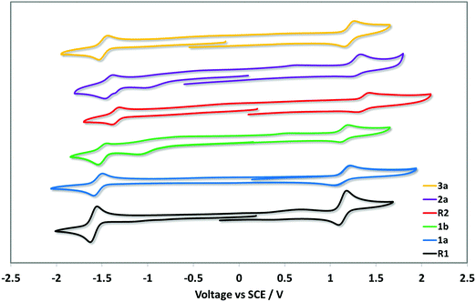 | ||
| Fig. 3 Cyclic voltammograms of 1a–5a measured in a deaerated MeCN with 0.1 M nBu4NPF6 at a scan rate of 100 mV s−1 in the positive scan direction and Fc/Fc+ as the internal standard, and are referenced with respect to SCE (Fc/Fc+ = 0.38 V in MeCN).21 | ||
| E ox1/2/V | ΔEp/mV | E red1/2/V | ΔEp/mV | E HOMO /eV | E LUMO /eV | ΔEredox/V | |
|---|---|---|---|---|---|---|---|
| a Measurements were carried out in degassed MeCN at a scan rate of 100 mV s−1 with Fc/Fc+ used as the internal reference and referenced with respect to SCE (Fc/Fc+ = 0.38 V in MeCN).21 b E HOMO/LUMO = −[Eox/redvs. Fc/Fc+ + 4.8] eV.22 | |||||||
| R1 | 1.13 | 90 | −1.61 | 70 | −5.93 | −3.20 | 2.74 |
| 1a | 1.13 | 180 | −1.54 | 100 | −5.93 | −3.26 | 2.67 |
| 1b | 1.15 | 70 | −1.52 | 90 | −5.95 | −3.29 | 2.67 |
| R2 | 1.35 | 90 | −1.37 | 80 | −6.16 | −3.43 | 2.72 |
| 2a | 1.29 | 90 | −1.43 | 70 | −6.10 | −3.38 | 2.72 |
| 3a | 1.21 | 100 | −1.49 | 120 | −6.01 | −3.37 | 2.70 |
Each complex displays a quasi-reversible oxidation wave attributed to an admixture of the Ir(III)/Ir(IV) redox couple and contributions from the aryl ring of C^N ligands.10 The addition of tert-butyl groups in 1a and 1b renders the oxidation somewhat less reversible compared to the reference R1 though the oxidation potentials remain essentially unchanged, despite the inductively electron-donating character of this substituent. Upon addition of aryl groups to the 4-pyridyl position, the oxidation waves are anodically shifted, a reflection of the moderately strong electron-withdrawing character of these groups. This anodic shifting is somewhat mitigated by the conjugation present between the 3,5-di-tert-butylphenyl substituent and the coordinating pyridine in 3a, while in R2 and 2a the aryl groups are oriented perpendicular as a function of the o-methyl substituents on the arene; the magnitude of the inductively electron-withdrawing character of the aryl group is further modulated by the presence of the more strongly electron-donating methoxy substituent in 2a (Eox = 1.29 V) compared to the methyl substituent in R2 (Eox = 1.35 V). In CH2Cl2, it has been previously shown that R2 has an oxidation wave at 1.14 V.8d Thus, the solvent has a unusually large influence on the oxidation potential of this complex. All complexes display a single quasi-reversible reduction wave within the electrochemical window of MeCN. Despite the consistent assignment that the reduction is localized on the ancillary dtBubpy ligand, the reduction potential varies over a moderately large range from −1.37 V for R2 to −1.61 V for R1. In CH2Cl2R2 exhibits an irreversible reduction at −1.15 V.18 The most inductively electron-withdrawing substituents on the C^N ligands induce the greatest shift to less negative potentials in R2 and 2a, this via modulation of the electron density on the iridium centre. Analogous to that observed for the oxidation potentials, this effect is counteracted by the increased conjugation present in 3a. Surprisingly, despite the electron-donating nature of the tert-butyl groups, the reduction potential is not further cathodically shifted, but instead is −1.54 V for 1a and −1.52 V for 1b.
UV-Vis absorption spectroscopy
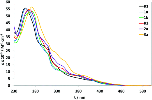
The absorption spectra for all complexes recorded in aerated MeCN at 298 K are shown in Fig. 4 and the data summarized in Table 2.| λ abs/nm (ε/M−1 cm−1)a | |
|---|---|
| a Recorded in aerated MeCN at 298 K. | |
| R1 | 255 (56![[thin space (1/6-em)]](https://www.rsc.org/images/entities/char_2009.gif) 853), 286 (34 853), 286 (34![[thin space (1/6-em)]](https://www.rsc.org/images/entities/char_2009.gif) 421), 309 (28 421), 309 (28![[thin space (1/6-em)]](https://www.rsc.org/images/entities/char_2009.gif) 841), 329 (16 841), 329 (16![[thin space (1/6-em)]](https://www.rsc.org/images/entities/char_2009.gif) 244), 408 (3757), 466 (663) 244), 408 (3757), 466 (663) |
| 1a | 258 (55![[thin space (1/6-em)]](https://www.rsc.org/images/entities/char_2009.gif) 115), 309 (22 115), 309 (22![[thin space (1/6-em)]](https://www.rsc.org/images/entities/char_2009.gif) 533), 323 (12 533), 323 (12![[thin space (1/6-em)]](https://www.rsc.org/images/entities/char_2009.gif) 442), 340 (10 442), 340 (10![[thin space (1/6-em)]](https://www.rsc.org/images/entities/char_2009.gif) 817), 374 (7397), 410 (3976), 448 (941) 817), 374 (7397), 410 (3976), 448 (941) |
| 1b | 272 (53![[thin space (1/6-em)]](https://www.rsc.org/images/entities/char_2009.gif) 237), 310 (22 237), 310 (22![[thin space (1/6-em)]](https://www.rsc.org/images/entities/char_2009.gif) 321), 329 (12 321), 329 (12![[thin space (1/6-em)]](https://www.rsc.org/images/entities/char_2009.gif) 109), 377 (7477), 397 (5357), 410 (4408), 429 (2455), 470 (837) 109), 377 (7477), 397 (5357), 410 (4408), 429 (2455), 470 (837) |
| R2 | 267 (54![[thin space (1/6-em)]](https://www.rsc.org/images/entities/char_2009.gif) 540), 310 (24 540), 310 (24![[thin space (1/6-em)]](https://www.rsc.org/images/entities/char_2009.gif) 832), 331 (13 832), 331 (13![[thin space (1/6-em)]](https://www.rsc.org/images/entities/char_2009.gif) 504), 344 (12 504), 344 (12![[thin space (1/6-em)]](https://www.rsc.org/images/entities/char_2009.gif) 153), 385 (6752), 419 (3826), 471 (675) 153), 385 (6752), 419 (3826), 471 (675) |
| 2a | 265 (53![[thin space (1/6-em)]](https://www.rsc.org/images/entities/char_2009.gif) 788), 296 (33 788), 296 (33![[thin space (1/6-em)]](https://www.rsc.org/images/entities/char_2009.gif) 350), 310 (28 350), 310 (28![[thin space (1/6-em)]](https://www.rsc.org/images/entities/char_2009.gif) 049), 343 (14 049), 343 (14![[thin space (1/6-em)]](https://www.rsc.org/images/entities/char_2009.gif) 195), 385 (7269), 419 (4019), 467 (855) 195), 385 (7269), 419 (4019), 467 (855) |
| 3a | 272 (56![[thin space (1/6-em)]](https://www.rsc.org/images/entities/char_2009.gif) 407), 311 (29 407), 311 (29![[thin space (1/6-em)]](https://www.rsc.org/images/entities/char_2009.gif) 765), 327 (23 765), 327 (23![[thin space (1/6-em)]](https://www.rsc.org/images/entities/char_2009.gif) 945), 350 (17 945), 350 (17![[thin space (1/6-em)]](https://www.rsc.org/images/entities/char_2009.gif) 179), 402 (6388), 439 (2460), 472 (993) 179), 402 (6388), 439 (2460), 472 (993) |
The acquired absorption data for R1,231b24 and R28d match those previously reported. For all complexes, the electronic absorption spectra show intense (ε on the order of 5.5 × 10⁴ M−1 cm−1) high-energy absorption bands between 255–272 nm that are assigned to 1π–π* ligand-centred (1LC) transitions on both the C^N and N^N ligands. With respect to R1, complex 3a shows a modest red-shift of the 1LC band that is due to the greater conjugation of the 3,5-di-tert-butylphenyl ring with the pyridine while a similar red-shifting compared to R1 of this band is observed for 1b, also due to LUMO stabilization of the C^N ligands. The profiles of the low-energy bands are found to be insensitive to the nature of the substituents on the C^N ligands. All complexes show moderately intense absorption bands in the range of 300 to 340 nm, which are assigned to spin-allowed mixed metal-to-ligand charge transfer transitions (1MLCT) and ligand-to-ligand charge transfer transitions (1LLCT). Weaker absorption bands are observed beyond 400 nm, tailing to 490 nm. These bands are assigned to spin-forbidden (3MLCT/3LLCT) transitions.25
Photophysical properties
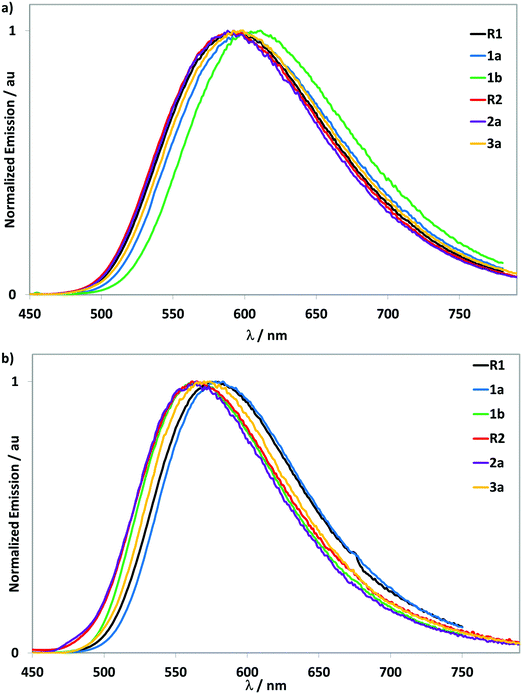 | ||
| Fig. 5 Emission spectra. (a) recorded at 298 K in deaerated MeCN, with λexc = 400 nm, (b) dropcast thin films at 298 K, with λexc = 400 nm. | ||
| MeCN | Neat film | |||||||
|---|---|---|---|---|---|---|---|---|
| λ PL /nm | τ PL /ns | Φ PL , /% | k r × 10−5/s−1 | k nr × 10−5/s−1 | λ PL /nm | τ PL , /ns | Φ PL /% | |
| a Recorded at 298 K in deaerated MeCN, with λexc = 400 nm. b [Ru(bpy)3]Cl2·6H2O was used as reference (ΦPL = 0.04 in 10−5 M aerated H2O).26 c k r = τPL/ΦPL. d k nr = 1/(τPL − kr) = [(1 − ΦPL)/τPL]. e Values refer to dropcast thin films at 298 K, with λexc = 400 nm. f With contribution of component in parentheses. g Values refer to dropcast thin films at 298 K using an integration sphere under an N2 environment. | ||||||||
| R1 | 592 | 581 | 31 | 3.61 | 13.60 | 578 | 5 (11.7%) | 23 |
| 29 (30.6%) | ||||||||
| 180 (57.7%) | ||||||||
| 1a | 597 | 497 | 26 | 3.42 | 16.70 | 579 | 9 (13.7%) | 40 |
| 40 (33.2%) | ||||||||
| 200 (53.1%) | ||||||||
| 1b | 611 | 250 | 12 | 3.20 | 36.80 | 565 | 8 (7.7%) | 27 |
| 43 (23.4%) | ||||||||
| 225 (68.9%) | ||||||||
| R2 | 592 | 643 | 28 | 2.95 | 12.60 | 565 | 10 (16.4%) | 15 |
| 42 (37.5%) | ||||||||
| 171 (46.1%) | ||||||||
| 2a | 588 | 623 | 29 | 3.05 | 13.00 | 564 | 10 (14.4%) | 16 |
| 42 (35.5%) | ||||||||
| 179 (50.1%) | ||||||||
| 3a | 598 | 501 | 25 | 3.39 | 16.57 | 570 | 8 (13.8%) | 40 |
| 36 (34.3%) | ||||||||
| 183 (51.9%) | ||||||||
Upon excitation at 400 nm, all complexes show moderately intense yellow emission over a narrow range between 588 to 611 nm and show a broad and unstructured profile, indicative of an emission with mixed CT character. An increasing red-shifting of the emission spectra is observed upon addition of tert-butyl groups (5 nm, 140 cm−1 for R1 to 1a and 19 nm, 530 cm−1 for 1a to 1b). This trend is also observed for the LC band in the absorption spectra and correlates as well with a slightly smaller ΔEredox gaps. The effect of the addition of electron-donating groups on the phenyl rings of the C^N ligands has been shown to induce a red-shift of the emission.23a A red-shift of 6 nm (169 cm−1) in the emission spectrum is also observed for 3a compared to R1, which is due to stabilization of the triplet state as a result of the increased conjugation within the C^N ligands. Given the orthogonal conformation of the aryl groups in R2 and 2a there is expectedly no significant change in the emission energy, consistent with previous studies.8b,d This design approach permits a modulation of the bulkiness of the resulting complexes without substantially affecting the emission energy.
The photoluminescence quantum yield (ΦPL) values of all complexes are approximately in the same range (ΦPL ∼ 25–31%), except for notably red-shifted 1b, which shows a lower ΦPL of 12%. This finding is a logical consequence of the energy gap law, which states that the non-radiative decay rate increases with decreasing emission energy.27 These values are comparable to those obtained for related cationic iridium complexes emitting in the same energy region.3d,5,8a,23a,24,28 The emission decays are monoexponential and the lifetimes (τPL) are all in the submicrosecond regime. The addition of increasing numbers of tert-butyl groups on the C^N ligands result in a decrease in the τPL values, a consequence of an increase in the non-radiative decay rate, knr. Over the series of substituted complexes, the radiative decay rate, kr, remains similar, though lower than the reference complex R1.
Emission studies in neat films
In order to emulate the emissive layer in the LEEC devices, neat films of all complexes were prepared by drop-casting a dichloromethane solution onto a glass substrate, which was then dried under vacuum. The emission spectra of the neat films were recorded at 298 K open to air (Fig. 5b and Table 3). All complexes display blue-shifted, broad and unstructured emission spectra (∼30 nm, 820 cm−1) compared to the MeCN solution measurements. The absence of any red-shifting indicates that there is no excimer formation. Multi-exponential emission decay kinetics are observed for all complexes, with the longest component in each being significantly shorter than the τPL found in MeCN solution. Photoluminescence quantum yields for R1, R2 and 2a, remain essentially unchanged compared to solution measurements while those of 1a, 1b and 3a are enhanced, a function of reduced non-radiative decay in the neat film.LEEC devices
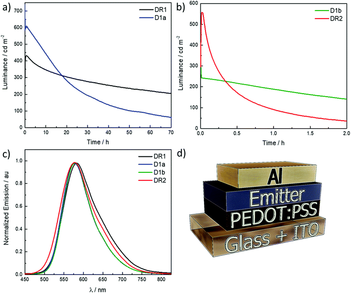
LEECs were prepared and the electroluminescence properties of complexes all complexes are shown in Fig. 6a–c while Fig. 6d describes the device architecture. The LEEC data are summarized in Table 4. The devices were built on ITO-patterned substrates, where poly(3,4-ethylenedioxythiophene):poly(styrenesulfonate) (PEDOT:PSS) layer (80 nm) was deposited by spin-coating. The LEEC active layer (100 nm) was deposited from MeCN by spin-coating, which contained the emitting complex mixed with the ionic liquid (IL) 1-butyl-3-methylimidazolium hexafluorophosphate, [Bmim][PF6], in a 4![[thin space (1/6-em)]](https://www.rsc.org/images/entities/char_2009.gif) :
:![[thin space (1/6-em)]](https://www.rsc.org/images/entities/char_2009.gif) 1 molar ratio (complex
1 molar ratio (complex![[thin space (1/6-em)]](https://www.rsc.org/images/entities/char_2009.gif) :
:![[thin space (1/6-em)]](https://www.rsc.org/images/entities/char_2009.gif) IL). Aluminium was evaporated as a top contact electrode. For simplicity, the LEECs are referred as DR1 to D3a containing complex R1 to 3a. LEECs were characterized by applying a bias and monitoring the emitted light over time. Unlike LEECs measured at constant voltage (DC), pulsed-current LEECs show faster response and improved device lifetime.29 The devices were characterized under an inert atmosphere by applying an average pulsed current (1 kHz, 50% duty cycle) of 100 A m−2.
IL). Aluminium was evaporated as a top contact electrode. For simplicity, the LEECs are referred as DR1 to D3a containing complex R1 to 3a. LEECs were characterized by applying a bias and monitoring the emitted light over time. Unlike LEECs measured at constant voltage (DC), pulsed-current LEECs show faster response and improved device lifetime.29 The devices were characterized under an inert atmosphere by applying an average pulsed current (1 kHz, 50% duty cycle) of 100 A m−2.
| Device | Lummaxa/cd m−2 | t on /s | t 1/2 /h | Efficacyd/cd A−1 | PEe/lm W−1 | EQEf/% | λ EL /nm | CIEh (x, y) |
|---|---|---|---|---|---|---|---|---|
| a Maximum luminance. b Time to reach maximum luminance. c Time to reach one-half of the maximum luminance. d Maximum efficacy. e Maximum power efficiency. f Maximum external quantum efficiency. g Wavelength emission in electroluminescence. h CIE coordinates obtained from the electroluminescence spectrum at maximum luminance. | ||||||||
| DR1 | 432 | 2400 | 62 | 4.3 | 2.3 | 1.8 | 582 | 0.50, 0.52 |
| D1a | 737 | 25 | 14 | 7.4 | 3.7 | 2.6 | 577 | 0.49, 0.50 |
| D1b | 353 | <5 | 1.3 | 3.4 | 1.4 | 1.2 | 578 | 0.51, 0.51 |
| DR2 | 557 | 54 | 0.3 | 5.6 | 2.1 | 2 | 578 | 0.47, 0.51 |
The yellow electroluminescence of the devices consists on one peak centred at 582 nm for DR1 and 577–578 nm for D1a, D1b and DR2 (see Fig. 6c). The electroluminescence spectra are narrower than the thin film photoluminescence spectra. The solubility of the D2a and D3a was poor (<15 mg mL−1) in both MeCN and CH2Cl2, which led to poor morphology quality of the spin-coated films and devices with high leakage currents. Even when the solution is filtered (200 nm porous size), the saturated solutions form grains during the solvent evaporation by spin-coating, which was confirmed by optical microscopy (see Fig. S25 in the ESI‡).
The LEECs DR1, D1a, D1b and DR2 exhibit instantaneous luminance that increases rapidly leading to short turn-on time (ton) of less than one minute, which is defined as the time to reach the maximum luminance, except DR1 where ton is 2400 s. The long ton is related with a slow evolution of the charge current equilibrium. A slow growth of the doped regions delays degradation and slows down the exciton-quenching rates.30 That would lead to more stable devices. In fact, DR1 has the highest t1/2. The devices are bright, with maximum luminance values in the same order of magnitude, between 350 and 750 cd m−2 across all devices. The devices are moderately efficient, with a maximum efficacy of 7.4 cd A−1 in the case of D1a. Lower efficiencies are achieved for D1b, DR1 and DR2, following the trend in the photoluminescence quantum yield of the thin film. However, the LEECs differs in terms of their stability, defined as time to reach half of the maximum luminance. DR1 has a lifetime above 62 hours, which makes it the most stable device within this study, maintaining almost constant the luminance over the time about 300 cd m−2. D1a has a higher luminance (737 cd m−2) although it is achieved only during few seconds and then proceeds to drop to ∼600 cd m−2, lasting for only 14 h. D1b and DR2 present low stabilities. Initially D1b displays luminance values around 350 cd m−2 but is stable for 1.3 h. DR2 shows higher turn-on luminance (∼550 cd m−2) however, the emission drops fast and the t1/2 only 0.3 h. The result comparison with previous works is complicated as the operational parameters are different.12 Pulse current is used to improve the device stability compared to what is obtained using a constant voltage driving. The limited stability of these devices relates in part to poor film-forming characteristics, leading to a morphology with imperfections, such as tiny dots. This was in particular the case for the films prepared with complexes 2a and 3a (ESI‡). Even though such imperfections were not identified for the films of the other complexes it is likely due to the similarity in the chemical structure that also here some film-forming issues are occurring, albeit at a smaller scale and dimension. This would also lead to pathways where the degradation is accelerated. Higher photoluminescence quantum yield values were published for similar complexes.8a The described imperfections in the film formation can explain the lower observed photoluminescence quantum yield. However, the obtained EQEs (1.2–2.6%) are in line with the typical values for efficient yellow LEECs. Indeed, only a few examples with high EQE (>6%) have been published for yellow/orange LEECs.3a,d,31 Furthermore, the EQE's appear in line with the PLQY of the films, again highlighting the main issue is the film formation.
Conclusions
In conclusion, we successfully synthesized and characterized a series of cationic Ir(III) complexes of the form [Ir(C^N)2(dtBubpy)]PF6 incorporating bulky substituents on the C^N ligand in order to develop new emissive materials for light-emitting electrochemical cells. The syntheses are straightforward allowing the introduction of tert-butyl, mesityl, manisyl, and 3,5-di-tert-butylphenyl groups into the C^N ligand. This systematic study revealed that the solubility of the complexes in standard organic solvents increased. At high concentrations (>15 mg mL−1) complexes 2a and 3a did not, however, show good solubility in MeCN and DCM. All complexes have been structurally characterised and the single crystal structure determinations of complexes 1a, 1b, R2 and 3a confirm that by increasing the sterical congestion of the substituent the inter-nuclear distance between adjacent complexes increased in the solid state. All complexes show bright yellow luminescence in MeCN, with moderate photoluminescence quantum yields. The yellow phosphorescence of the parent complex R1 is retained, due to a twisted conformation of the bulky aromatic substituents (in R2, 2a and 3a) as they do not extend the π-conjugated system of the C^N ligand. Neat film photoluminescence quantum yields of up to 40% could be obtained. Complexes R1, 1a, 1b and R2 were successfully employed in LEECs, showing yellow luminescence with moderate external quantum efficiencies.Experimental section
Synthesis
The compounds ClR2 and LR2 where synthesised according previously reported procedures.8bGeneral procedure I (for L1a and L1b)
A solution of tert-butylpyridine (1.0 equiv.) in CH2Cl2 was stirred at room temperature. Trifluoroacetic acid (1.0 equiv.) was added followed by phenylboronic acid (1.5 equiv.), water (12 mL), a solution of silver(I) nitrate (0.2 equiv.) in 8 mL of water and potassium persulfate (3.0 equiv.). The solution was stirred vigorously for 6 h. The reaction was quenched with water (10 mL), extracted with CH2Cl2 (50 mL) and washed with conc. aqueous NaHCO3 (10 mL). After layer separation, the brown yellow organic phase was dried over MgSO4 and the solvent was evaporated under vacuum leaving brown oil which was purified on silica (10% of EtOAc in petroleum ether). The desired fractions were combined and reduced until dryness yielding the desired compound as oil.General procedure II (for Cl2a and Cl3a)
A mixture of 2-chloro-4-iodopyridine (1.00 equiv.), the corresponding arylboronic acid (1.30 equiv.), 2 M aqueous K2CO3 (5.00 equiv.) and 1,4-dioxane (35 mL) was degassed for 15 min. Pd(Ph3)4 (0.04 equiv.) was added, and the reaction mixture was stirred at 95 °C for 3 days, then cooled to room temperature. Toluene (80 mL) was added. After layer separation the organic phase was washed with water (10 mL) and dried over MgSO4. The solvent was evaporated leaving a residue which was purified by column chromatography (15% EtOAc in petroleum ether on silica). The desired fractions were combined, and the solvent evaporated leaving the title compound as solid.Cl3a was obtained as a red solid (1.613 g, 5.346 mmol). Yield: 96%. Rf: 0.40 (10 vol% EtOAc in petroleum ether on silica). Mp: 68 °C. 1H NMR (400 MHz, chloroform-d) δ = 8.42 (d, 1H), 7.54 (d, 2H), 7.41 (m, 3H), 1.38 (s, 18H). 13C NMR (101 MHz, CDCl3) δ = 152.8, 152.0, 151.9, 149.8, 136.4, 123.8, 122.3, 121.4, 120.8, 35.0, 31.4. HR-MS (FTMS+): [M − H]+ calculated: (C19H25ClNH): 302.1670 found: 302.1668. CHN: calcd for C19H24ClN: C, 75.60; H, 8.01; N, 4.64. Found: C, 75.41; H, 7.93; N, 4.61.
General procedure III (for L2a and L3a)
A mixture of the corresponding 2-chloro-4-arylpyridine (1.00 equiv.), phenylboronic acid (1.50 equiv.), palladium(II) acetate (0.06 equiv.), PPh3 (0.26 equiv.), 2 M aqueous Na2CO3 (4.00 equiv.) and 1,2-dimethoxyethane (25 mL) was degassed for 15 min. The reaction mixture was heated to reflux for 24 h under Ar atmosphere, and then cooled to room temperature. CH2Cl2 (50 mL) was added. After layer separation the organic layer was washed with brine and dried over MgSO4. The solvent was evaporated leaving a residue, which was purified by column chromatography (10% petroleum ether in CH2Cl2). The desired fractions were combined, and the solvent evaporated leaving the desired compound as a solid.General procedure IV (for the synthesis of target complexes)
The iridium chloride (2.0 equiv.) and the corresponding C^N ligand (5.0 equiv.) were suspended in a mixture of 2-ethoxyethanol/water (75/25). The mixture was refluxed under stirring. After 24 h the mixture was allowed to cool to r.t. and distilled water was added. A precipitate was observed. The solid was washed with Et2O, H2O and dried under vacuum to give the intermediate [Ir(C^N)2Cl]2. A suspension of this dimer (1.0 equiv.), the ancillary ligand 4,4′-di-tert-butyl-2,2′-bipyridine (2.2 equiv.) and AgPF6 (2.5 equiv.) in 1,2-dichloroethane was kept at reflux for 2 h and stirred at r.t. for another 16 h. The solvent was then evaporated leaving a brown yellow residue, which was then placed in dichloromethane. A beige precipitate was observed. After filtration, the filtrate was reduced till dryness under reduced pressure, leaving a yellow-brown solid, which was purified on silica with dichloromethane and increasing percentages of methanol (0–8%). The desired fractions were collected and reduced to dryness, giving a yellow solid, which was suspended under stirring in a hexane/Et2O mixture (1/1) for 4 h. The yellow precipitate was filtered off and dissolved in methanol. An aqueous NH4PF6 solution was added dropwise resulting in a precipitate. The suspension was stirred vigorously for 2 h and subsequently filtered. The solid was dissolved in CH2Cl2 and washed with water. The layers were separated, and the organic layer was reduced to dryness, leaving a yellow solid, which was recrystallised through vapor diffusion using CH2Cl2 as the solvent and Et2O as the anti-solvent. After filtration, the target complexes were obtained as solids.Conflicts of interest
There are no conflicts to declare.Acknowledgements
We thank Umicore AG for the gift of materials. We thank the EPSRC UK National Mass Spectrometry Facility at Swansea University for analytical services. C. H. acknowledges the Région Bretagne, France for funding. E. Z.-C. acknowledges the University of St Andrews and EPSRC (EP/M02105X/1) for financial support. Financial support is also acknowledged from the Spanish Ministry of Economy and Competitiveness (MINECO) via the Unidad de Excelencia Maria de Maeztu MDM-2015-0538, MAT2017-88821-R and the Generalitat Valenciana (Prometeo/2016/135). J. A. thanks the Spanish Ministry of Education, Culture and Sport for his pre-doctoral grant. M.-G. L.-P. acknowledges support from a Grisolia Grant (No. GRISOLIA/2015/A/146).References
- (a) R. C. Evans, P. Douglas and C. J. Winscom, Coord. Chem. Rev., 2006, 250, 2093–2126 CrossRef; (b) A. F. Henwood and E. Zysman-Colman, Chem. Commun., 2017, 53, 807–826 RSC; (c) S. Ladouceur and E. Zysman-Colman, Eur. J. Inorg. Chem., 2013, 2985–3007 CrossRef; (d) K. P. S. Zanoni, R. L. Coppo, R. C. Amaral and N. Y. Murakami Iha, Dalton Trans., 2015, 44, 14559–14573 RSC; (e) M. S. Lowry and S. Bernhard, Chem. – Eur. J., 2006, 12, 7970–7977 CrossRef PubMed.
- (a) H. Xu, R. Chen, Q. Sun, W. Lai, Q. Su, W. Huang and X. Liu, Chem. Soc. Rev., 2014, 43, 3259–3302 RSC; (b) E. Longhi and L. De Cola, in Iridium(III) in Optoelectronic and Photonics Applications, ed. E. Zysman-Colman, John Wiley & Sons, Ltd, 2017, pp. 205–274 Search PubMed; (c) J.-H. Jou, S. Kumar, A. Agrawal, T.-H. Li and S. Sahoo, J. Mater. Chem. C, 2015, 3, 2974–3002 RSC; (d) D. Ma, T. Tsuboi, Y. Qiu and L. Duan, Adv. Mater., 2017, 29, 1603253 CrossRef PubMed.
- (a) A. F. Henwood and E. Zysman-Colman, in Iridium(III) in Optoelectronic and Photonics Applications, John Wiley & Sons, Ltd, 2017, pp. 275–357 Search PubMed; (b) S. B. Meier, D. Tordera, A. Pertegás, C. Roldán-Carmona, E. Ortí and H. J. Bolink, Mater. Today, 2014, 17, 217–223 CrossRef; (c) C. E. Housecroft and E. C. Constable, Coord. Chem. Rev., 2017, 350, 155–177 CrossRef; (d) A. F. Henwood and E. Zysman-Colman, Top. Curr. Chem., 2016, 374, 36 CrossRef PubMed.
- For recent reviews on LEECs see: R. D. Costa, E. Ortí, H. J. Bolink, F. Monti, G. Accorsi and N. Armaroli, Angew. Chem., Int. Ed., 2012, 51, 8178–8211 CrossRef PubMed.
- H. C. Su, F. C. Fang, T. Y. Hwu, H. H. Hsieh, H. F. Chen, G. H. Lee, S. M. Peng, K. T. Wong and C. C. Wu, Adv. Funct. Mater., 2007, 17, 1019–1027 CrossRef.
- G. G. Malliaras, J. D. Slinker, J. A. DeFranco, M. J. Jaquith, W. R. Silveira, Y.-W. Zhong, J. M. Moran-Mirabal, H. G. Craighead, H. D. Abruna and J. A. Marohn, Nat. Mater., 2008, 7, 168 CrossRef.
- V. N. Kozhevnikov, Y. Zheng, M. Clough, H. A. Al-Attar, G. C. Griffiths, K. Abdullah, S. Raisys, V. Jankus, M. R. Bryce and A. P. Monkman, Chem. Mater., 2013, 25, 2352–2358 CrossRef.
- (a) D. R. Martir, C. Momblona, A. Pertegás, D. B. Cordes, A. M. Z. Slawin, H. J. Bolink and E. Zysman-Colman, ACS Appl. Mater. Interfaces, 2016, 8, 33907–33915 CrossRef PubMed; (b) D. Rota Martir, A. K. Bansal, V. Di Mascio, D. B. Cordes, A. F. Henwood, A. M. Z. Slawin, P. C. J. Kamer, L. Martinez-Sarti, A. Pertegas, H. J. Bolink, I. D. W. Samuel and E. Zysman-Colman, Inorg. Chem. Front., 2016, 3, 218–235 RSC; (c) A. F. Henwood, A. K. Bansal, D. B. Cordes, A. M. Z. Slawin, I. D. W. Samuel and E. Zysman-Colman, J. Mater. Chem. C, 2016, 4, 3726–3737 RSC; (d) D. Rota Martir, G. J. Hedley, D. B. Cordes, A. M. Z. Slawin, D. Escudero, D. Jacquemin, T. Kosikova, D. Philp, D. M. Dawson, S. E. Ashbrook, I. D. W. Samuel and E. Zysman-Colman, Dalton Trans., 2016, 45, 17195–17205 RSC.
- K. J. Suhr, L. D. Bastatas, Y. Shen, L. A. Mitchell, B. J. Holliday and J. D. Slinker, ACS Appl. Mater. Interfaces, 2016, 8, 8888–8892 CrossRef PubMed.
- A. M. Bünzli, E. C. Constable, C. E. Housecroft, A. Prescimone, J. A. Zampese, G. Longo, L. Gil-Escrig, A. Pertegás, E. Ortí and H. J. Bolink, Chem. Sci., 2015, 6, 2843–2852 RSC.
- (a) H. J. Bolink, E. Coronado, R. N. D. Costa, N. Lardiés and E. Ortì, Inorg. Chem., 2008, 47, 9149–9151 CrossRef PubMed; (b) A. B. Tamayo, S. Garon, T. Sajoto, P. I. Djurovich, I. M. Tsyba, R. Bau and M. E. Thompson, Inorg. Chem., 2005, 44, 8723–8732 CrossRef PubMed.
- (a) J. D. Slinker, A. A. Gorodetsky, M. S. Lowry, J. Wang, S. T. Parker, R. Rohl, S. Bernhard and G. G. Malliaras, J. Am. Chem. Soc., 2004, 126, 2763 CrossRef PubMed; (b) L. Sun, A. Galan, S. Ladouceur, J. D. Slinker and E. Zysman-Colman, J. Mater. Chem., 2011, 21, 18083–18088 RSC.
- R. D. Costa, E. Ortí, H. J. Bolink, S. Graber, C. E. Housecroft and E. C. Constable, J. Am. Chem. Soc., 2010, 132, 5987–5989 CrossRef PubMed.
- H. J. Bolink, E. Coronado, R. D. Costa, E. Ortì, M. Sessolo, S. Graber, K. Doyle, M. Neuburger, C. E. Housecroft and E. C. Constable, Adv. Mater., 2008, 20, 3910–3913 CrossRef.
- R. D. Costa, E. Ortí, H. J. Bolink, S. Graber, C. E. Housecroft and E. C. Constable, Adv. Funct. Mater., 2010, 20, 1511–1520 CrossRef.
- I. B. Seiple, S. Su, R. A. Rodriguez, R. Gianatassio, Y. Fujiwara, A. L. Sobel and P. S. Baran, J. Am. Chem. Soc., 2010, 132, 13194–13196 CrossRef PubMed.
- M. Nonoyama, Bull. Chem. Soc. Jpn., 1974, 47, 767–768 CrossRef.
- M. Lepeltier, T. K.-M. Lee, K. K.-W. Lo, L. Toupet, H. Le Bozec and V. Guerchais, Eur. J. Inorg. Chem., 2005, 110–117 CrossRef.
- For recent reviews see: L. Flamigni, A. Barbieri, C. Sabatini, B. Ventura and F. Barigelletti, Top. Curr. Chem., 2007, 281, 143–203 CrossRef.
- K. J. Suhr, L. D. Bastatas, Y. Shen, L. A. Mitchell, G. A. Frazier, D. W. Taylor, J. D. Slinker and B. J. Holliday, Dalton Trans., 2016, 45, 17807–17823 RSC.
- V. V. Pavlishchuk and A. W. Addison, Inorg. Chim. Acta, 2000, 298, 97–102 CrossRef.
- C. M. Cardona, W. Li, A. E. Kaifer, D. Stockdale and G. C. Bazan, Adv. Mater., 2011, 23, 2367–2371 CrossRef PubMed.
- (a) K. Hasan, A. K. Bansal, I. D. W. Samuel, C. Roldán-Carmona, H. J. Bolink and E. Zysman-Colman, Sci. Rep., 2015, 5, 12325 CrossRef PubMed; (b) For examples see: S. Ladouceur, D. Fortin and E. Zysman-Colman, Inorg. Chem., 2011, 50, 11514–11526 CrossRef PubMed.
- M. S. Lowry, W. R. Hudson, R. A. Pascal Jr. and S. Bernhard, J. Am. Chem. Soc., 2004, 126, 14129–14135 CrossRef PubMed.
- S. Ladouceur, D. Fortin and E. Zysman-Colman, Inorg. Chem., 2010, 49, 5625–5641 CrossRef PubMed.
- H. Ishida, S. Tobita, Y. Hasegawa, R. Katoh and K. Nozaki, Coord. Chem. Rev., 2010, 254, 2449–2458 CrossRef.
- (a) J. V. Caspar and T. J. Meyer, J. Phys. Chem., 1983, 87, 952–957 CrossRef; (b) M. Bixon, J. Jortner, J. Cortes, H. Heitele and M. E. Michel-Beyerle, J. Phys. Chem., 1994, 98, 7289–7299 CrossRef.
- R. D. Costa, E. Ortì, H. J. Bolink, S. Graber, S. Schaffner, M. Neuburger, C. E. Housecroft and E. C. Constable, Adv. Funct. Mater., 2009, 19, 3456–3463 CrossRef.
- D. Tordera, S. Meier, M. Lenes, R. D. Costa, E. Ortí, W. Sarfert and H. J. Bolink, Adv. Mater., 2012, 24, 897–900 CrossRef PubMed.
- M. Lenes, G. Garcia-Belmonte, D. Tordera, A. Pertegás, J. Bisquert and H. J. Bolink, Adv. Funct. Mater., 2011, 21, 1581–1586 CrossRef.
- For representative of white-emitting LEECs see: L. He, J. Qiao, L. Duan, G. Dong, D. Zhang, L. Wang and Y. Qiu, Adv. Funct. Mater., 2009, 19, 2950–2960 CrossRef.
- A. Deb, S. Manna, A. Maji, U. Dutta and D. Maiti, Eur. J. Org. Chem., 2013, 5251–5256 CrossRef.
- A. L. Kanibolotsky, R. Berridge, P. J. Skabara, I. F. Perepichka, D. D. C. Bradley and M. Koeberg, J. Am. Chem. Soc., 2004, 126, 13695–13702 CrossRef PubMed.
Footnotes |
| † The research data supporting this publication can be accessed at http://dx.doi.org/10.17630/f766e0be-41bd-4acf-82d7-4a621ac4c783 |
| ‡ Electronic supplementary information (ESI) available: NMR spectra for ligands and complexes; supplementary LEEC fabrication data. CCDC 1034962, 1038996, 1039805 and 1045877. For ESI and crystallographic data in CIF or other electronic format see DOI: 10.1039/c8tc01130c |
| This journal is © The Royal Society of Chemistry 2018 |

