Highly transparent, strong, and flexible fluorographene/fluorinated polyimide nanocomposite films with low dielectric constant†
Xiaodong
Yin‡
a,
Yiyu
Feng‡
 abc,
Qiang
Zhao
d,
Yu
Li
abc,
Shuangwen
Li
a,
Huanli
Dong
abc,
Qiang
Zhao
d,
Yu
Li
abc,
Shuangwen
Li
a,
Huanli
Dong
 d,
Wenping
Hu
 d and
Wei
Feng
 *abce
*abce
aSchool of Materials Science and Engineering, Tianjin University, P. R. China. E-mail: weifeng@tju.edu.cn; Fax: +86-22-87402059
bKey Laboratory of Advanced Ceramics and Machining Technology, Ministry of Education, P. R. China
cTianjin Key Laboratory of Composite and Functional Materials, Tianjin 300072, P. R. China
dInstitute of Chemistry, Chinese Academy of Sciences, Beijing 100190, P. R. China
eCollaborative Innovation Center of Chemical Science and Engineering, Tianjin, P. R. China
First published on 3rd May 2018
Abstract
Optimization of molecular interactions between filler materials and a polymer matrix is one of the key methods to improve the dielectric properties of composite films. In films composed of two-dimensional fluorographene (FG) and fluorinated polyimide (f-PI), the repulsion between the C–F bonds hinders the dispersion of the filler in the matrix. In this work, we describe a low dielectric constant FG/f-PI nanocomposite film obtained by the preparation of f-PI on exfoliated FG grafted with 2,2′-bis(trifluoromethyl)-[1,1′-biphenyl]-4,4′-diamine (t-FG). The strong interfacial interaction between f-PI and t-FG promotes the dispersion of t-FG in the f-PI matrix. The effects of the addition of t-FG on the optical, mechanical, and dielectric properties of the composite film are investigated by incorporating different amounts of t-FG. When the t-FG content reaches 0.75 wt%, we obtain a transparent, strong, and flexible t-FG/f-PI composite film, which exhibits a low dielectric constant (2.09) and a high tensile strength (300.1 MPa). An organic thin-film transistor fabricated using this film as a dielectric layer exhibits good transistor mobility and ON/OFF ratio. t-FG/f-PI dielectric films are therefore suitable for application in transparent flexible displays.
Introduction
Developing transparent and flexible substrates with good dielectric properties is important for the fabrication of high-performance flexible displays.1–3 Materials with low dielectric constant (k) can reduce the interconnecting resistance/capacity (RC) delay, cross-talking, and power dissipation, which make them suitable as interlayer dielectrics (e.g., transistor devices), semiconductor packaging materials (e.g., chips modules), and high-frequency, low-loss boards.4–7 Furthermore, the mechanical strength, absorption properties and thermal resistance of dielectric materials endow them with stability, optical transparency, and the ability to operate over wide temperature ranges.8,9 So far, however, dielectric materials combining low dielectric constant, high-strength, good thermal stability, and high transparency have seldom been reported.10Fluorinated polyimide (f-PI) has been proposed as a potential candidate dielectric material because of its low dielectric constant (k ≤ 3), good transparency (the transmittance in the visible region is larger than 85%), and excellent chemical and thermal stability (Tg ≥ 250 °C and Td5% ≥ 450 °C).11–13 Recently, the incorporation of inorganic dielectric fillers in a polymer matrix has been shown to further improve the dielectric and mechanical properties of the composite material.14–21 Among the materials of potential practical relevance, two-dimensional fluorographene (FG), with a tunable F/C ratio and a number of C–F bonds, is one of the most promising dielectric nanofillers, because of its extremely low dielectric constant (ca. 1.2), good transparency in the visible region, and the presence of highly electronegative groups.22 The low value of the dielectric constant is related to the reduced polarizability of the C–F bonds compared to the C–H bonds, and by the fact that highly electronegative groups inhibit the formation of charge transfer complexes between conjugated f-PI molecular structures.12,13
Obtaining a good dispersion of FG nanosheets in a polymer matrix is challenging, because of the hydrophobic and oleophobic nature of these materials. Previous work18 has shown that simple mixing methods are unable to disperse FG nanosheets uniformly in an PI matrix, which results in a dielectric constant (k = 2.48), which is larger than the threshold recommended for low-k materials (k ≤ 2.4) in the International Technology Roadmap for Semiconductors (ITRS).23 This relatively high value of k is caused by the tendency of FG to aggregate within the PI matrix, owing to repulsive forces between neighboring C–F bonds.22 Therefore, optimizing the molecular interactions between FG and f-PI, to promote the interfacial compatibility of the two materials, is a crucial requisite in the fabrication of uniform nanocomposites combining low dielectric constant, high strength, and high transparency. Chemical modification of FG nanosheets using organic molecules offers a great promise to impart good compatibility and dispersibility with f-PI for uniform composites.16,20,21 The molecules linked to FG could form different interfacial interactions with electronegative atoms or anions, thus showing the improvement of the dielectric or mechanical properties of the composites.
In this study, we describe an efficient approach to prepare 2,2′-bis(trifluoromethyl)-[1,1′-biphenyl]-4,4′-diamine (TFDB)-grafted FG (t-FG)/f-PI composite films. In our method, t-FG nanosheets are exfoliated by solvothermal intercalation with TFDB, which is linked to FG via H-bonds. t-FG provides a reactive platform for the fabrication of composite films, which can be achieved by grafting poly(amic acid) (PAA) at the reactive sites of the t-FG nanosheets, followed by thermal imidization. We show that this process produces a transparent, strong, and uniform t-FG/f-PI nanocomposite film. We also investigate the influence of dispersed t-FG on the optical, mechanical, and dielectric properties of t-FG/f-PI films by varying the t-FG content in the sample. Finally, we describe the fabrication of an organic thin-film transistor (OTFT) device using the t-FG/f-PI composite film as a dielectric layer.
Experimental
Materials
F-graphite (F/C = 0.9) was purchased from Hubei Zhuoxi Fluorination Technology Co., Ltd, 4,4′-(hexafluoroisopropylidene)diphthalic anhydride (6FDA) and TFDB were obtained from ChinaTech Chemical Co., Ltd, and acetonitrile (ACN, 99.5%, ultradry) and N-methyl pyrrolidone (NMP, 99.5%, ultradry) were purchased from Energy and Chemicals, whereas 2,6-diphenylanthracene (DPA) was synthesized at the Institute of Chemistry of the Chinese Academy of Sciences.Preparation of t-FG by the exfoliation of F-graphite
F-graphite (50 mg) and TFDB (0.5 mg) were dispersed in 30 mL of ACN. The mixture was transferred into a Teflon-lined autoclave and heated at 90 °C for 10 h. After intercalation, the resulting mixture was ultrasonicated at 100 W for 18 h for exfoliation. The supernatant t-FG nanosheets were obtained by centrifugation at 5000 rpm for 30 min. 5 mL of NMP was added to the t-FG solution and distilled at reduced pressure to remove ACN. The preparation procedure for the NMP-dispersed t-FG nanosheets is illustrated in Fig. 1.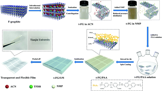 | ||
| Fig. 1 Schematic illustration of the preparation of transparent and flexible t-FG/f-PI composite films by the fabrication of f-PI on t-FG exfoliated with TFDB. | ||
Preparation of t-FG/f-PI composite films
TFDB (2.40 g, 7.5 mmol) and NMP (16.97 mL) were mixed in a three-necked 100 mL glass reactor under argon. The solution was stirred at 25 °C, and 6FDA (3.40 g, 7.5 mmol) dissolved in 15 mL of NMP was then slowly (1 h) added to the TFDB solution using a constant pressure funnel under argon. The mixture was further stirred vigorously under argon at 25 °C for 48 h, and a transparent and viscous PAA solution was obtained. A certain content of the t-FG solution was added to the PAA solution slowly (1 h) and the mixture was further stirred vigorously for 6 h.The t-FG/f-PI composite films were prepared by spin-coating t-FG/PAA solutions onto clean coverslips at 1000 rpm and then kept in a vacuum oven at 60 °C for 2 h. The thermal imidization process was performed at 80 °C for 2 h and at 100 °C, 150 °C, 200 °C, 250 °C, and 300 °C for 1 h under argon, respectively. The thickness of the t-FG/f-PI composite films was controlled by varying the spinning speed and the concentration and volume of the t-FG/PAA solution. The synthesis of the t-FG/f-PI composite films is illustrated in Fig. 1. A transparent and flexible t-FG/f-PI composite film was produced by peeling off the product from the coverslips. This method is simple and versatile and can be used to fabricate a variety of uniform t-FG/f-PI composite films. The films with t-FG content of 0.25, 0.50, 0.75 and 1 wt% (compared to f-PI monomers) will be indicated in this work as t-FG0.25/f-PI, t-FG0.50/f-PI, t-FG0.75/f-PI, and t-FG1.00/f-PI, respectively. In addition, pure f-PI films were also prepared under the same conditions.
Fabrication of the OTFT device
The t-FG/f-PI composite films were used as dielectric layers in an OTFT device. The bottom-gate Al electrode was deposited on a glass substrate. A t-FG/PAA solution was then spin-coated at 7000 rpm for 30 s on a hydrophilic treated Al/glass substrate and subjected to the thermal imidization process (80 °C for 2 h and 100 °C, 150 °C, 200 °C, 250 °C, and 300 °C for 1 h under argon, respectively) to form a dielectric layer. DPA was then evaporated to form a 40 nm thick semiconductor layer. Finally, a 20 nm thick Au source–drain electrode was deposited. An OTFT device with a channel length (L) of 25 μm and a width (W) of 5.25 mm was then prepared, and its structure is shown in Fig. S1 (ESI†).Measurement and characterisation
The morphology of t-FG was studied using transmission electron microscopy (TEM, JEOL JEM-2100F). Atomic force microscopy (AFM) measurements were performed on a Dimension ICON-PT. X-ray diffraction (XRD) patterns were obtained using an X-ray diffractometer (BRUKER AXS GMBH, D8 Advanced) with CuKα radiation at a wavelength of 0.154 nm, a scanning rate of 5.0° min−1, a voltage of 40 kV, and a current of 40 mA. Raman spectra were recorded on a DXR Microscope (Thermo Electron Corporation, America) using He laser beam excitation (λ = 632.8 nm). The interaction between FG and TFDB was investigated using differential scanning calorimetry (DSC, Q20, TA Instruments). X-ray photoelectron spectroscopy (XPS) measurements were performed at a power level of 450 W using a PHI 1600 surface analysis system equipped with an Mg Kα anode.The morphology of pure f-PI and t-FG/f-PI composite films was studied using scanning electron microscopy (SEM, Philips XL30E) and TEM (JEOL JEM-2100F). The microstructures of the films were characterized by Fourier transform infrared spectroscopy (FTIR, BRUKER AXSGMBH, FTIR650). The ultraviolet-visible (UV-vis) spectra of the films were recorded on a UV-vis spectrophotometer (Shimadzu, UV3600). The mechanical properties of the films were studied using an XQ-1 tensile tester at a tensile rate of 3 mm min−1. Dielectric measurements were performed on an E4980A capacitance analyzer (Agilent, USA) under ambient conditions with two parallel plate modes in the frequency range 102–106 Hz. Water absorption was evaluated by comparing the mass of the samples before and after soaking in distilled water for 24 h at room temperature, as from the ASTM D570-98 (Reapproved 2010) standard. The glass transition temperature (Tg) of the films was determined from DSC (Q20, TA Instruments). Thermogravimetric analysis (TGA, NETZSCH STA 449C) was conducted to investigate the thermal properties of the f-PI and t-FG/f-PI composite films in a nitrogen atmosphere in the temperature range 30–800 °C at a heating rate of 10 °C min−1. The coefficient of thermal expansion (CTE) was obtained on a TMA-Q400 (TA Instruments) with a stretching model in a nitrogen atmosphere. AFM was used to investigate the surface roughness of the composite films. The OTFT device was tested using a Keithley 4200-SCS analyzer.
Results and discussion
Characterization of t-FG
The t-FG nanosheets were prepared by solvothermal intercalation followed by exfoliation. The driving force of the intercalation process is related to the process Gibbs free energy (ΔG), which is defined in eqn (1):| ΔG = ΔH − TΔS | (1) |
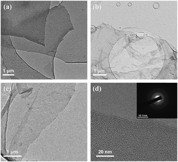
The morphology of t-FG nanosheets exfoliated by intercalation at different temperatures was examined using TEM. As shown in Fig. 2, t-FG exfoliated at 80 °C (Fig. 2a) has a thick structure, whereas the samples exfoliated at 90 °C (Fig. 2b) and 100 °C (Fig. 2c) exhibit a transparent, silky, and wrinkled nanosheet structure, with a lateral dimension of more than 5 μm. However, high temperatures cause the defluorination of t-FG, which leads to a decrease in the F/C ratio (Table S1, ESI†).26 The high-resolution image (Fig. 2d) shows the presence of well-defined edges on the t-FG nanosheets exfoliated by intercalation at 90 °C. Furthermore, the t-FG nanosheets present a disordered hexagonal structure (the inset in Fig. 2d) because of the presence of C–F bonds on the surface. Meanwhile, it can be clearly seen from the AFM image of Fig. S2 (ESI†) that the thickness of the prepared t-FG is about 1.36 nm, which indicates that it could be thought of as a single layer. These results demonstrate that t-FG nanosheets can be exfoliated by solvothermal intercalation using TFDB. The t-FG nanosheets with a high aspect ratio (≥5000) provide a potentially well-dispersed nanofiller, which is suitable to improve the dielectric and mechanical properties of polymer-based nanocomposites.
The structure of the t-FG nanosheets was analyzed using XRD (Fig. 3a). F-graphite and t-FG exhibit a peak at about 2θ = 13.5°, which can be assigned to the (001) reflection of a hexagonal crystal structure, particularly for compounds with very high F content.27,28 F-graphite exhibits a (002) reflection peak, which is broadened by the presence of stacking faults. This peak disappears after exfoliation.29 The XRD results indicate that the disorder of the t-FG nanosheets along the stacking direction increases after the TFDB treatment and the formation of H-bonds. Raman spectroscopy was used to further characterize the structure of the t-FG nanosheets. Two prominent peaks, corresponding to the D and G bands, were observed (Fig. 3b). The D band appears at approximately 1350 cm−1, and is characteristic of graphene with a certain degree of disorder. The G band, at approximately 1590 cm−1, is associated with the conjugated structure of the sp2 carbon domains. The intensity ratio of the D and G bands (ID/IG) can be used to estimate the amount of defects in graphene.30ID/IG increases in t-FG from 1.04 (F-graphite) to 1.31 after exfoliation. This is attributed to an increase in the concentration of defects in the structure of t-FG, caused by the interaction of FG and TFDB.21 The surface packing of TFDB is indicated by the presence of a peak at approximately 1000 cm−1, corresponding to the breathing vibration of the aromatic ring.12
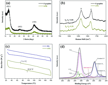 | ||
| Fig. 3 (a) The XRD patterns and (b) Raman spectra of F-graphite and t-FG, (c) DSC traces of FG and t-FG, and (d) C 1s XPS spectra of t-FG. | ||
The formation of the H-bonds between TFDB and FG is particularly important for the intercalation and dispersion of t-FG in the f-PI matrix. According to previous studies, diamine is likely to form H-bonds with electronegative atoms or anions.21,22,31 In this study, we use DSC to verify the presence of molecular H-bonds (Fig. 3c). FG shows no obvious peak during heating and cooling periods. Compared to FG, t-FG shows an endothermic heat flow during the heating period at 95.8 °C and an exothermic peak during the cooling period at 71.4 °C, which we attribute to the breakdown and formation of H-bonds, respectively.32,33
The elemental composition and chemical bonds of the t-FG nanosheets were studied using X-ray photoemission spectroscopy (XPS). As shown in Fig. 3d, the C 1s spectra can be deconvoluted into several symmetric component peaks. In the case of t-FG, the peaks at 284.9 eV and 284.5 eV are assigned to sp3 C–C bonds and sp2 C![[double bond, length as m-dash]](https://www.rsc.org/images/entities/char_e001.gif) C bonds, respectively. Besides, three peaks are observed at 290.25, 291.1, and 292.4 eV, which are ascribed to covalent C–F, C–F2, and C–F3 bonds, respectively.34,35 A further peak is observed at 289.95 eV, ascribed to the C–N bond of TFDB on t-FG. Interestingly, t-FG also exhibits a peak at 288.82 eV in the C 1s spectra, which indicates the presence of semi-ionic C–F bonds. The presence of these semi-ionic bonds is probably caused by the shift in the electron cloud of the covalent C–F bonds induced by the formation of H-bonds. The formation of different types of C–F bonds in consequence to the formation of H-bonds can be exploited to tune the dielectric constant of t-FG.26 Single-layer t-FG nanosheets treated with TFDB can be used to prepare low dielectric constant nanocomposites using f-PI as a well-dispersed nanofiller.
C bonds, respectively. Besides, three peaks are observed at 290.25, 291.1, and 292.4 eV, which are ascribed to covalent C–F, C–F2, and C–F3 bonds, respectively.34,35 A further peak is observed at 289.95 eV, ascribed to the C–N bond of TFDB on t-FG. Interestingly, t-FG also exhibits a peak at 288.82 eV in the C 1s spectra, which indicates the presence of semi-ionic C–F bonds. The presence of these semi-ionic bonds is probably caused by the shift in the electron cloud of the covalent C–F bonds induced by the formation of H-bonds. The formation of different types of C–F bonds in consequence to the formation of H-bonds can be exploited to tune the dielectric constant of t-FG.26 Single-layer t-FG nanosheets treated with TFDB can be used to prepare low dielectric constant nanocomposites using f-PI as a well-dispersed nanofiller.
Morphology and properties of f-PI and t-FG/f-PI composite films
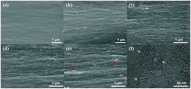
The dispersion of t-FG in the f-PI matrix was examined using SEM. Fig. 4a–e shows the fractured surface of the t-FG/PI composite films at various t-FG contents. The pure f-PI film exhibits a smooth and flat fractured surface (Fig. 4a). After the incorporation of t-FG, the composite film adopts a multi-layered structure with a rough fracture surface (Fig. 4b–e). This indicates that the fracture mode of the films changes from non-plastic to plastic after the t-FG addition. This effect may be attributed to the in-plane orientation of f-PI grafted by t-FG during the film preparation.18 Moreover, at a t-FG content of 0.75%, t-FG nanosheets appear to be well dispersed in the f-PI matrix with a good compatibility between the two materials, as shown in the TEM images (Fig. 4f, arrows). The homogeneous dispersion of t-FG in the f-PI matrix can be attributed to the strong interfacial interactions between t-FG and the PAA chains, and to the fact that t-FG maintains individual nanosheets and homogeneity during the thermal imidization of the grafted PAA chains in the t-FG layers. When the t-FG content increases to 1 wt%, some t-FG nanosheets aggregate in the PI matrix (arrow in Fig. 4e). These results indicate that the dispersibility of t-FG in the f-PI matrix can be controlled by optimizing the molecular interactions at the interface using an appropriate t-FG content.The transparency of the dielectric layer is important in the fabrication of transparent flexible displays. The dispersion and transparency of the individual fillers and of the polymer matrix determine the overall transparency of the composite film. For graphene/PI composites, intra- and intermolecular charge transfer interactions between PI and the nanosheet aggregates affect the transparency. As shown in Fig. S5 (ESI†), all t-FG/f-PI composite films (thickness: 3 ± 0.25 μm) show a high optical transparency, with transmittance values of >90% at 500–800 nm and ≥85% at 400 nm. Varying the t-FG content from 0.25 wt% to 0.75 wt% only results in a slight decrease in transparency. The transparency exhibited by t-FG/f-PI composite films is far superior to that reported in previous studies.17 The high transparency of t-FG/f-PI is attributed to the combined effect of the optical transparency of t-FG and f-PI with well-dispersed nanofillers. Strong polar trifluoromethyl groups in f-PI and polar C–F bonds in t-FG reduce intra- and intermolecular charge transfer interactions.12 Moreover, good dispersion reduces the diffuse reflection of light at the surface. The corresponding optical photographs of pure f-PI and t-FG/f-PI composite films are displayed in Fig. S6 (ESI†). All films show a good transparency. A reduction in transparency by almost 1% is observed when the t-FG content reaches 1%. It has been reported that a graphene layer significantly increases optical opacity, owing to repeated absorption and interfacial reflection.36 In the case of t-FG/f-PI films with 1% FG content, it is therefore likely that the agglomeration of t-FG (Fig. 4e) is responsible for the observed increase in optical opacity.
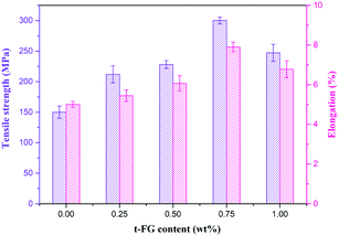
The strength and flexibility of a dielectric material are also important properties for its application in flexible displays. t-FG with a high aspect ratio (over 5000) can be used as a nanofiller to enhance the strength of the composite films. Fig. 5 shows the tensile strength and elongation at break as a function of the t-FG content. The introduction of well-dispersed t-FG increases the tensile strength and the elongation at break of f-PI. This effect is further enhanced by increasing the content of t-FG to 1 wt%. At 0.75 wt% content, the t-FG0.75/f-PI composite films exhibit the highest tensile strength (300.1 MPa), which is higher than that reported in previous studies (Table 1), and an elongation at break (7.9%) with a Young's modulus of 4.79 GPa (Fig. S7, ESI†). The tensile strength and elongation at break of this composition are therefore 100% and 58% higher, respectively, than those of f-PI (150.2 MPa and 5.01%). This enhancement in mechanical properties is caused by the strong interfacial adhesion (H-bonds and van der Waals attraction forces) and by the synergistic effects between t-FG and f-PI, which promote the efficient transfer of stress from the f-PI matrix to the t-FG filler at the interface.20,21 When the t-FG content is further increased to 1 wt%, the formation of t-FG aggregates leads to a decrease in tensile strength (247.2 MPa) and elongation at break (6.78%).
| Ref. | Nanofiller | Polymer matrix | Tensile strength (MPa) | Dielectric constant | |
|---|---|---|---|---|---|
| material | Content (wt%) | ||||
| Our work | t-FG | 0.75 | f-PI | 300.1 | 2.09 |
| 18 | FG | 0.50 | PI | 237 | 2.48 |
| 19 | FG | 1.00 | PI | N/A | 2.1 |
| 20 | Graphene fluoroxide | 1.00 | PI | 110 | 2.75 |
| 21 | Graphene fluoroxide | 0.30 | PI | 159 | 2.29 |
| 37 | Fluorine-containing graphene oxide | 0.60 | PI | 141 | 2.34 |
In materials for flexible displays, dielectric properties are particularly important. The ability to retain charge and to dissipate energy during the reorientation of the microscopic dipole moments in a dielectric is related to the dielectric constant and to the loss tangent (tan![[thin space (1/6-em)]](https://www.rsc.org/images/entities/char_2009.gif) δ). Fig. 6 shows the dependence of these quantities on the t-FG content in the t-FG/f-PI composite films. At 1 MHz, f-PI has a dielectric constant (2.82) and a loss tangent (0.0028) that are lower than other PI-based derivatives, owing to the presence of CF3 groups, which are characterized by low polarizability.13 The incorporation of t-FG in f-PI results in a decrease of both k and tan
δ). Fig. 6 shows the dependence of these quantities on the t-FG content in the t-FG/f-PI composite films. At 1 MHz, f-PI has a dielectric constant (2.82) and a loss tangent (0.0028) that are lower than other PI-based derivatives, owing to the presence of CF3 groups, which are characterized by low polarizability.13 The incorporation of t-FG in f-PI results in a decrease of both k and tan![[thin space (1/6-em)]](https://www.rsc.org/images/entities/char_2009.gif) δ as the t-FG content increases. Minimum values of both k (2.09) and tan
δ as the t-FG content increases. Minimum values of both k (2.09) and tan![[thin space (1/6-em)]](https://www.rsc.org/images/entities/char_2009.gif) δ (0.0019) are reached for the t-FG0.75/f-PI film, which are lower than those reported in previous studies as shown in Table 1.18–21
δ (0.0019) are reached for the t-FG0.75/f-PI film, which are lower than those reported in previous studies as shown in Table 1.18–21
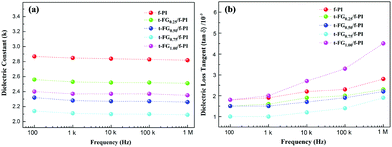 | ||
| Fig. 6 Dielectric constant (a) and dielectric loss tangent (b) of f-PI and t-FG/f-PI composite films at different frequencies. | ||
The low dielectric properties of t-FG/f-PI films can mainly be attributed to the low polarizability of the C–F bonds and to the presence of well-dispersed single-layer t-FG nanosheets with high aspect ratios. Single-layer t-FG nanosheets with large specific surface areas adsorb and interact with the f-PI chains, hindering the motion of the molecular dipoles of f-PI and constraining their relaxation. Furthermore, the strong electron-withdrawing nature of the F atoms reduces the energy of the discrete electronic levels of the composite film.19 As a result, the electronic polarization is reduced and the dielectric constant decreases further. This is confirmed by the fact that, in the t-FG1.00/f-PI film, both k and tan![[thin space (1/6-em)]](https://www.rsc.org/images/entities/char_2009.gif) δ increase (to 2.35 and 0.0045, respectively), owing to the agglomeration of t-FG in the PI matrix.21 The presence of t-FG nanosheet aggregates (Fig. 4e) leads to a less effective hindrance of the f-PI chain dipole mobility and to a phase separation. Furthermore, interfacial polarization appears at the interface between the aggregated t-FG and the f-PI matrix. These results are in agreement with previous studies.16–21
δ increase (to 2.35 and 0.0045, respectively), owing to the agglomeration of t-FG in the PI matrix.21 The presence of t-FG nanosheet aggregates (Fig. 4e) leads to a less effective hindrance of the f-PI chain dipole mobility and to a phase separation. Furthermore, interfacial polarization appears at the interface between the aggregated t-FG and the f-PI matrix. These results are in agreement with previous studies.16–21
Performance of OTFT devices
As demonstrated in the above results, for relatively large (0.75 wt%) amounts of well-dispersed single-layer t-FG nanosheets, highly transparent and flexible t-FG/f-PI composite films can be obtained, which combine low dielectric constant and loss tangent, high strength, low water absorption (0.1%, Fig. S8, ESI†), and good thermal stability (Fig. S9 and Table S2, ESI†). These films are suitable for the fabrication of OTFT devices. To test their efficiency as OTFT components, we fabricated an OTFT device using the t-FG0.75/f-PI film as a dielectric layer. AFM analysis indicates that the root-mean-square surface roughness of the t-FG0.75/f-PI film is 0.943 nm (Fig. S10, ESI†). Fig. 7a shows the output characteristics of this OTFT device, showing the drain current (IDS) as a function of the drain voltage (VDS) for different gate voltage (VGS) values. Typical transfer curves are shown in Fig. 7b for an operating voltage VDS = −20 V.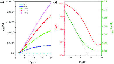 | ||
| Fig. 7 Output curves (a) and transfer curves (b) of an OTFT device using a t-FG0.75/f-PI composite film as a dielectric layer. | ||
The thin dielectric layer has a low gate current leakage, owing to its surface smoothness.8 The field effect transistor mobility (μ) and threshold voltage (VT) can be obtained in eqn (2):
 | (2) |
Conclusions
We have presented an efficient strategy to prepare uniform t-FG/f-PI composite films. Our approach is based on improving the interfacial interaction between the two materials. As a dispersed nanofiller, single-layer t-FG nanosheets with a lateral dimension of more than 5 μm were exfoliated by solvothermal intercalation with TFDB, which is linked to FG via H-bonds. The linkage of f-PI on t-FG promotes the interfacial interaction and results in a good dispersibility of t-FG in the f-PI matrix. When a t-FG content of 0.75 wt% is reached, t-FG shows good homogeneity within the f-PI matrix, owing to strong interfacial interactions. Highly transparent and flexible t-FG0.75/f-PI composite films combine low dielectric constant (2.09) and tangent loss (0.0019) with high tensile strength (300.1 MPa), low water absorption (0.1%), and good thermal stability. Furthermore, OTFT devices fabricated using t-FG0.75/f-PI composite films as a dielectric layer exhibit good transistor mobility (0.21 cm2 V−1 s−1) and ON/OFF ratio (4.2 × 10³). Transparent and flexible t-FG0.75/f-PI composite films with very low dielectric constants are therefore suitable for application in transparent flexible displays.Conflicts of interest
There are no conflicts to declare.Acknowledgements
This work was financially supported by the National Key R&D Program of China (No. 2016YFA0202302), the National Natural Science Funds for Distinguished Young Scholars (No. 51425306), the State Key Program of National Natural Science Foundation of China (No. 51633007), and National Natural Science Foundation of China (No. 51573125 and 51773147).References
- H. Sirringhaus, N. Tessler and R. H. Friend, Science, 1998, 280, 1741 CrossRef PubMed.
- A. Dodabalapur, Z. Bao, A. Makhija, J. G. Laquindanum, V. R. Raju, Y. Feng, H. E. Katz and J. Rogers, Appl. Phys. Lett., 1998, 73, 142 CrossRef.
- J. A. Spechler, T. Koh, J. T. Herb, B. P. Rand and C. B. Arnold, Adv. Funct. Mater., 2016, 25, 7428 CrossRef.
- H. Treichel, G. Ruhl, P. Ansmann, R. Wurl, C. Muller and M. Dietlmeier, Microelectron. Eng., 1998, 40, 1 CrossRef.
- G. Maier, Prog. Polym. Sci., 2001, 26, 3 CrossRef.
- R. Farrell, T. Goshal, U. Cvelbar, N. Petkov and M. A. Morris, Electrochem. Soc. Interface, 2001, 20, 39 CrossRef.
- A. P. Palov, E. N. Voronina, T. V. Rakhimova, D. V. Lopaev, S. M. Zyryanov, Y. A. Mankelevich, M. B. Krishtab and M. R. Baklanov, J. Vac. Sci. Technol., B, 2016, 34, 041205 Search PubMed.
- K. K. Min, W. K. Dong, S. H. Moon, D. W. Shin, T. S. Oh and J. B. Yoo, Mater. Sci. Eng., B, 2017, 217, 7 CrossRef.
- Z. P. Xu, M. Li, M. Xu, J. H. Zhou, H. Tao, L. Wang and J. B. Peng, Org. Electron., 2017, 44, 225 CrossRef.
- Y. W. Liu, C. Qian, L. G. Qu, Y. N. Wu, Y. Zhang, X. H. Wu, B. Zou, W. X. Chen, Z. Q. Chen, Z. G. Chi, S. W. Liu, X. D. Chen and J. R. Xu, Chem. Mater., 2016, 27, 6543 CrossRef.
- M. C. Jia, M. T. Zhou, Y. J. Li, G. L. Lu and X. Y. Huang, Polym. Chem., 2018, 9, 920 RSC.
- H. J. Ni, J. G. Liu, Z. H. Wang and S. Y. Yang, J. Ind. Eng. Chem., 2015, 28, 16 CrossRef.
- R. X. Bei, C. Qian, Y. Zhang, Z. G. Chi, S. W. Liu, X. D. Chen, J. R. Xu and M. P. Aldred, J. Mater. Chem. C, 2017, 5, 12807 RSC.
- C. K. Min, T. B. Wu, W. T. Yang and C. L. Chen, Compos. Sci. Technol., 2008, 68, 1570 CrossRef.
- H. Q. Guo, F. F. Liu, J. Y. Zhao, H. B. Yao, R. Z. Jin, C. Q. Kang, Z. Bian, X. P. Qiu and L. X. Gao, J. Mater. Chem. C, 2015, 3, 11531 RSC.
- J. Y. Wang, S. Y. Yang, Y. L. Huang, H. W. Tien, W. K. Chin and C. C. M. Ma, J. Mater. Chem., 2011, 21, 13569 RSC.
- X. Y. Ye, P. W. Gong, J. Q. Wang, H. G. Wang, S. L. Ren and S. R. Yang, Composites, Part A, 2015, 75, 96 CrossRef.
- P. P. Zhang, J. P. Zhao, K. Zhang, R. Bai, Y. M. Wang, C. X. Hua, Y. Y. Wu, X. X. Liu, H. B. Xu and Y. Li, Composites, Part A, 2016, 84, 428 CrossRef.
- X. Wang, Y. Y. Dai, W. M. Wang, M. M. Ren, B. Y. Li, C. Fan and X. Y. Liu, ACS Appl. Mater. Interfaces, 2014, 6, 16182 Search PubMed.
- X. Chen, H. H. Huang, X. Shu, S. M. Liu and J. Q. Zhao, RSC Adv., 2017, 7, 1956 RSC.
- Z. G. Chen, S. M. Liu, S. J. Yan, X. Shu, Y. C. Yuan, H. H. Huang and J. Q. Zhao, Mater. Des., 2017, 117, 150 CrossRef.
- W. Feng, P. Long, Y. Y. Feng and Y. Li, Adv. Sci., 2016, 3, 1500413 CrossRef PubMed.
- A. Allan, D. Edenfeld, W. H. Joyner, A. B. Kahng, M. Rodgers and Y. Zorian, Computer, 2002, 35, 42 CrossRef.
- S. D. Bergin, V. Nicolosi, P. V. Streich, S. Giordani, Z. Y. Sun and A. H. Windle, Adv. Mater., 2010, 20, 1876 CrossRef.
- Z. H. Tang, J. Zhuang and X. Wang, Langmuir, 2010, 26, 9045 CrossRef PubMed.
- C. B. Sun, Y. Y. Feng, Y. Li, C. Q. Qin, Q. Q. Zhang and W. Feng, Nanoscale, 2014, 6, 2634 RSC.
- A. Hamwi, J. Phys. Chem. Solids, 1993, 57, 677 CrossRef.
- P. W. Gong, Z. F. Wang, J. Q. Wang, H. G. Wang, Z. P. Li, Z. J. Fan, Y. Xu, X. X. Han and S. R. Yang, J. Mater. Chem., 2012, 22, 16950 RSC.
- K. Guerin, J. P. Pinheiro, M. Dubois, Z. Fawal, F. Masin, R. Yazami and A. Hamwi, Chem. Mater., 2004, 16, 1786 CrossRef.
- H. R. An, Y. Li, Y. Gao, C. Cao, J. K. Han, Y. Y. Feng and W. Feng, Carbon, 2017, 116, 338 CrossRef.
- K. K. Tadi, S. Pal and T. N. Narayanan, Sci. Rep., 2016, 6, 25221 CrossRef PubMed.
- Y. F. Li, F. Y. Li and Z. F. Chen, J. Am. Chem. Soc., 2012, 134, 11269 CrossRef PubMed.
- P. Long, Y. Y. Feng, Y. Li, C. Cao, S. W. Li, H. R. An, C. Q. Qin, J. K. Han and W. Feng, ACS Appl. Mater. Interfaces, 2017, 9, 37981 Search PubMed.
- J. T. Robinson, J. S. Burgess, C. E. Junkermeier, S. C. Badescu, T. L. Reinecke, F. K. Perkins, M. K. Zalalutdniov, J. W. Baldwin, J. C. Culbertson, P. E. Sheehan and E. S. Snow, Nano Lett., 2010, 10, 3001 CrossRef PubMed.
- R. R. Nair, W. Ren, R. Jalil, I. Riaz, V. G. Kravets, L. Britnell, P. Blake, F. Schedin, A. S. Mayorov, S. J. Yuan, M. I. Katsnelson, H. M. Cheng, W. Strupinski, L. G. Bulusheva, A. V. Okotrub, I. V. Grigorieva, A. N. Grigorenko, K. S. Novoselo and A. K. Geim, Small, 2010, 6, 2877 CrossRef PubMed.
- R. R. Nair, P. Blake, A. N. Grigorenko, K. S. Novoselov, T. J. Booth, T. Stauber, N. M. R. Peres and A. K. Geim, Science, 2008, 320, 1308 CrossRef PubMed.
- Z. G. Chen, H. H. Huang, S. J. Yan, Z. P. Zheng, S. M. Liu, Y. C. Yuan, J. Q. Zhao and Y. Fu, Ind. Eng. Chem. Res., 2017, 56, 9926 CrossRef.
Footnotes |
| † Electronic supplementary information (ESI) available: The structure of organic thin-film transistor; the chemical position of t-FG exfoliated by solvothermal intercalation; the AFM image and XPS survey spectra of t-FG nanosheets; FT-IR spectra, optical transmission spectra, Young's modulus, water absorption, glass transition temperature, TGA thermograms and coefficients of thermal expansion of f-PI and t-FG/f-PI composite films; AFM surface 3D image of the t-FG/f-PI composite film. See DOI: 10.1039/c8tc00998h |
| ‡ These authors contributed equally to this work. |
| This journal is © The Royal Society of Chemistry 2018 |

