
 Open Access Article
 This Open Access Article is licensed under a Creative Commons Attribution-Non Commercial 3.0 Unported Licence
Effect of halide ratio and Cs+ addition on the photochemical stability of lead halide perovskites†
Sebastian
Svanström
a,
T. Jesper
Jacobsson
 b,
Tamara
Sloboda
c,
Erika
Giangrisostomi
d,
Ruslan
Ovsyannikov
d,
Håkan
Rensmo
a and
Ute B.
Cappel
*c
b,
Tamara
Sloboda
c,
Erika
Giangrisostomi
d,
Ruslan
Ovsyannikov
d,
Håkan
Rensmo
a and
Ute B.
Cappel
*c
aDivision of Molecular and Condensed Matter Physics, Department of Physics and Astronomy, Uppsala University, Box 516, SE-751 20 Uppsala, Sweden
bDepartment of Chemistry, Ångström Laboratory, Uppsala University, Box 538, 75121 Uppsala, Sweden
cDivision of Applied Physical Chemistry, Department of Chemistry, KTH Royal Institute of Technology, SE-100 44 Stockholm, Sweden
dInstitute Methods and Instrumentation for Synchrotron Radiation Research, Helmholtz-Zentrum Berlin GmbH, Albert-Einstein-Straße 15, 12489 Berlin, Germany. E-mail: cappel@kth.se
First published on 26th July 2018
Abstract
Lead halide perovskite solar cells with multi-cation/mixed halide materials now give power conversion efficiencies of more than 20%. The stability of these mixed materials has been significantly improved through the addition of Cs+ compared to the original methylammonium lead iodide. However, it remains one of the most significant challenges for commercialisation. In this study, we use photoelectron spectroscopy (PES) in combination with visible laser illumination to study the photo-stability of perovskite films with different compositions. These include Br![[thin space (1/6-em)]](https://www.rsc.org/images/entities/char_2009.gif) :I ratios of 50:50 and 17:83 and compositions with and without Cs+. For the samples without Cs and the 50:50 samples, we found that the surface was enriched in Br and depleted in I during illumination and that some of the perovskite decomposed into Pb0, organic halide salts, and iodine. After illumination, both of these reactions were partially reversible. Furthermore, the surfaces of the films were enriched in organic halide salts indicating that the cations were not degraded into volatile products. With the addition of Cs+ to the samples, photo-induced changes were significantly suppressed for a 50:50 bromide to iodide ratio and completely suppressed for perovskites with a 17:83 ratio at light intensities exceeding 1 sun equivalent.
:I ratios of 50:50 and 17:83 and compositions with and without Cs+. For the samples without Cs and the 50:50 samples, we found that the surface was enriched in Br and depleted in I during illumination and that some of the perovskite decomposed into Pb0, organic halide salts, and iodine. After illumination, both of these reactions were partially reversible. Furthermore, the surfaces of the films were enriched in organic halide salts indicating that the cations were not degraded into volatile products. With the addition of Cs+ to the samples, photo-induced changes were significantly suppressed for a 50:50 bromide to iodide ratio and completely suppressed for perovskites with a 17:83 ratio at light intensities exceeding 1 sun equivalent.
Introduction
Lead halide perovskites were first applied in solar cells as a light absorber in dye-sensitized solar cells with a power conversion efficiency below 4% and poor stability.1 Since then they have evolved from simple methylammonium lead iodide (MAPbI3) to complex multi-cation/halide mixed materials with efficiencies over 22% and significantly improved long term stability.2–7 Most perovskite films are deposited directly from solutions, allowing short iteration times and fast optimisation.8 This is further enhanced by inherent excellent optoelectronic properties like: a direct band gap, strong absorption, high dielectric constant, and long charge carrier diffusion lengths, as well as benign defects.9 The perovskites also benefit from a broad flexibility in terms of compositional engineering where the halogens, the cations as well as the lead can be replaced, either fully or partially.10 By for example changing the Br:I ratio, the band gap is tuneable between 1.6 eV and 2.3 eV making perovskites interesting for both single junction and tandem architectures.11
However, a number of challenges remains before perovskites solar cells will be able to compete with traditional solar cells commercially. Stability is a key problem with perovskites being sensitive to oxygen,12 moisture,13,14 high temperatures15 and UV-radiation.16 For a material expected to last 25+ years in hot, humid, and oxygen rich conditions while exposed to rain and UV-radiation, this is a challenge that must be dealt with. Another potential issue is JV-hysteresis, where the perovskite solar cells exhibit different properties depending on scan rate and direction. JV-hysteresis is believed to be partially caused by the migration of ions, mainly I−, Br−, MA+, FA+, and Cs+, and is affected by the internal electric field.17–19 The stability and efficiency of the perovskites have improved significantly by tuning the bromide:iodide ratio, and through addition of Cs+ or more recently Rb+ and K+.3,20–23 The mechanism by which these modifications affect the stability are not completely understood but it has been suggested that the addition of Cs+ improves crystallinity, suppresses phase separation and decreases the defect density at the grain boundaries.3,22,24
In order to provide a deeper understanding of the working mechanisms and details of the processes influencing the perovskite stability, methods that can assess light-induced changes at an atomic level are needed. Such techniques are also of general interest for materials science to assess the interaction of materials and their surfaces with light. We have previously shown that photoelectron spectroscopy (PES) can be used to study the chemical changes of the perovskite surfaces during illumination.25 Those experiments were carried out on FA0.85MA0.15Pb(Br0.15I0.85)3 under illumination with a 515 nm laser and were conducted at the LowDosePES endstation26 at the synchrotron BESSY II. By using a low X-ray flux and a high efficiency spectrometer (Angular resolved Time-of-Flight, ArTOF), sample degradation by the X-ray photons on the sample was negligible.25 At other beamlines, also the X-rays themselves can cause sample degradation, which makes it difficult to distinguish visible light-induced from X-ray-induced effects. Our measurements at the LowDosePES endstation avoid this issue and we were able to investigate the effects of visible illumination in situ. We found that illumination influences the relative concentration of halides (Br, I) and lead at the perovskite surface, most likely as a consequence of halide migration and an accompanying phase separation, and also causes the formation of metallic lead (Pb0). Both processes were found to be partially reversible.
In this study, we expand our previous work by comparing the photo-induced effects for perovskite films with different compositions. In particular, we investigate the impact of the Br:I ratio and of the addition of Cs+. Two specific Br:I ratios were used, 17:83 and 50:50. The 17:83 ratio (in particular as FA0.83MA0.17Pb(Br0.17I0.83)3) is one of the compositions that during the last few years has delivered the highest device efficiencies and stabilities.3,5,27,28 The 50:50 compositions (e.g. as here FA0.83MA0.17Pb(Br0.5I0.5)3) have a higher band gap (1.87 eV compared to 1.63 eV) and are interesting for tandem application10,29,30 but phase separation under illumination has been a problem at these Br:I ratios.10,31–37 Addition of a small percentage of Cs ions at the A cation site has turned out to be an efficient way of stabilising the mixed perovskites and some of the best cells so far have used compositions with Cs+, e.g. Cs0.05FA0.79MA0.16Pb(Br0.17I0.83)3.3,22,27,38,39 To investigate the connections to phase separation and ion migration under illumination, as well the stabilisation mechanism, we included perovskites containing Cs+ with a Br:I ratio of both 17:83, and 50:50 (i.e. Cs0.05FA0.79MA0.16Pb(Br0.17I0.83)3 and Cs0.05FA0.79MA0.16Pb(Br0.5I0.5)3). Finally, we also investigated the behaviour of Cs0.17FA0.83Pb(Br0.17I0.83)3 where Cs+ has fully replaced the MA ions. This composition has been suggested as an efficient and potentially stable alternative in tandem devices.10,40
Experimental
Three perovskites with a Br:I ratio of 17:83 were investigated: a mixed perovskite with MA and FA (MA0.17FA0.83PbBr0.51I2.49), a mixed perovskite with three cations including caesium (Cs0.05MA0.16FA0.79PbBr0.51I2.49) and a MA free perovskite (Cs0.17FA0.83PbBr0.51I2.49). From here on these will be referred to as 17:83, 17:83 + Cs and CsFA, respectively. Furthermore, two perovskites with a Br:I ratio of 50:50 were also investigated: mixed 50:50 perovskite (MA0.17FA0.83PbBr1.5I1.5) and mixed 50:50 with caesium (Cs0.05MA0.15FA0.8PbBr1.5I1.5). These are referred to as 50:50 and 50:50 + Cs, respectively. All of the perovskites are deposited on mesoporous TiO2. The compositions and the short names are summarised in Table 1.
| Composition | Short name | a | b | c | d | e | f |
|---|---|---|---|---|---|---|---|
| MA0.17FA0.83PbBr0.51I2.49 | 17:83 |
83 | — | — | — | 17 | — |
| Cs0.05MA0.16FA0.79PbBr0.51I2.49 | 17:83 + Cs |
79 | — | — | — | 16 | 5 |
| Cs0.17FA0.83PbBr0.51I2.49 | CsFA | 83 | — | 17 | — | — | — |
| MA0.17FA0.83PbBr1.5I1.5 | 50:50 |
41.5 | 8.5 | — | 41.5 | 8.5 | — |
| Cs0.05MA0.16FA0.79PbBr1.5I1.5 | 50:50 + Cs |
39.5 | 8 | — | 39.5 | 8 | 5 |
Perovskite precursor solutions were prepared in a glovebox with a nitrogen atmosphere with a small excess of PbI2, which was previously found beneficial for device performance.41 Stock solutions of PbI2 and PbBr2 were prepared in advance whereas the final precursor solutions were prepared just before perovskite deposition. Anhydrous DMF:DMSO in the proportion 4:1 was used as solvent for the perovskite solutions. Six master solutions were prepared: (a) 1.25 M PbI2 and 1.14 M FAI, (b) 1.25 M PbI2 and 1.14 M MAI, (c) 1.25 M PbI2 and 1.14 M CsI, (d) 1.25 M PbBr2 and 1.14 M FABr, (e) 1.25 M PbBr2 and 1.14 M MABr, (f) 1.38 M CsI in DMSO. The final perovskite solutions were prepared by mixing the stock solutions according to Table 1. The MA and FA salts were bought from GreatCell solar, the lead salts from TCI, solvents from Fisher Scientific and the remaining chemicals from Sigma Aldrich. All chemicals were used as received without further treatment.
The perovskite deposition is described in detail in the ESI.† In short, perovskites were spin-coated on FTO substrates with a TiO2/mesoporous TiO2 blocking layer in a N2 filled glovebox using a one-step anti-solvent method with chlorobenzene as the anti-solvent. The deposited films were annealed at 100 °C in the glove box for 30–60 min and then stored in dry air. UV-vis absorption measurements of the perovskite films were performed using an Ocean Optics spectrophotometer HR-2000 c with a deuterium and a halogen lamp.
Steady state photoluminescence was measured with a Fluorolog, Horiba Jobon Yvon, FL-1065 spectrometer. A white tungsten lamp was used as luminous source. A monochromator was placed between the sample and the light source as well as between the sample and the detector. An excitation wavelength of 435 nm was used for all samples. Photoluminescence spectra were measured from 455 nm to 835 nm in steps of one nm. The excitation source and the detector were placed at 90° with respect to each other. The sample was orientated at 60° with respect to the excitation source in order to decrease interference from reflected light.
X-ray diffractograms were recorded with a Siemens D5000 Diffractometer using a parallel beam geometry with an X-ray mirror and a parallel plate collimator of 0.4°. The X-ray source was Cu Kα emission with a wavelength of 1.54 Å. The angle of incidence was 2° and 2θ scans were performed between 10° and 70° with a step size of 0.1°. SEM imaging was carried out on a Zeiss LEO 1550 scanning electron microscope.
Samples were stored and transported in darkness and low moisture atmosphere before introduction to sub-10−9 mbar pressures at the LowDosePES endstation at the PM4 beamline at the BESSY-II synchrotron for measurements.26 A detailed description of the endstation can be found in ref. 25 and 26. Monochromatization of the incoming X-ray radiation was performed with a plane grating monochromator with 360 lines per mm and the beam was focused to a sub-100 μm spot on the sample. Photoemission from the sample was measured using an ARTOF-2 spectrometer with an acceptance angle of 30°. To be able to use the ARTOF-2 spectrometer, the beamline was operated in pseudo-single bunch mode via a mechanical chopper.26,42 The ArTOF raw data was converted to intensity versus kinetic energy using the IGOR ArTOF loader and analysis package. The spectra were then energy calibrated by measuring the Fermi level or the Au4f level of a gold foil mounted on the manipulator and setting the binding energy of the Fermi level to 0 eV or the binding energy of Au4f7/2 to 84 eV. For the steady state characterisation, the peaks were energy calibrated against Pb5d5/2 at 19.8 eV (ref. 43) with the exception of spectra recorded with 540 eV photon energy, which were energy calibrated against Pb4f7/2 at 138.6 eV.44
The second harmonic (515 nm) of the laser system installed at the beamline (Tangerine model from Amplitude Systems) was used for visible illumination of the samples with a pulse length of about 350 fs and a repetition frequency of 208.33 kHz (i.e. 1/6 of the repetition rate of the synchrotron pulses). Spatial overlap between the X-ray and the laser pulses was achieved in the same way as described previously,25 and the overlap was checked on an Yttrium Aluminium Garnet (YAG) crystal mounted on the same manipulator as the sample on a regular basis. For the presented measurements, the full width at half maxima (FWHM) of the laser spot in the horizontal direction and vertical direction were estimated to be 0.42 mm and 0.30 mm on the YAG crystal. This gives a FWHM area of 0.098 mm2, meaning that 76% of the power falls within this area. Two laser powers were used (0.20 mW and 0.91 mW), which gives approximate power densities of 155 mW cm−2 and 706 mW cm−2, respectively.
Time evolution measurements of different core levels with the ArTOF spectrometer in fixed mode were carried out with the laser with the following sequence: 5 minute baseline measurement before the laser was switched on, 30 minutes measurement with the laser and 30 minutes without the laser to observe any post-illumination reactions. Each time evolution measurement was carried out on a fresh sample spot, which had not been exposed to laser illumination before. To ensure that the kinetic energy, and thus the probing depth, was kept constant, a photon energy of 90 eV was chosen for Pb5d, 120 eV for I4d, and 139 eV for Br3d. Due to the low kinetic energy (around 65 eV), the probing depth is estimated to be below 2 nm (ref. 45) and as such we are unable to directly measure the bulk during illumination. However, reactions in the bulk are likely to be reflected in the surface structure if ions from the perovskite migrate and the perovskite restructures itself.16,19,25,46 A combination of low cross-section, low photon flux, low concentrations and high background make the measurement of the core levels relating to N and Cs (i.e. elements included in the monovalent cations) during illumination challenging, and therefore those are not included in the analysis. After initial processing in IGOR Pro, the time evolution spectra were exported to MATLAB, where they were peak fitted with a series of Gaussian peaks to obtain changes in intensity and position of the core level peaks.
To characterise the surface composition of the perovskite, both before and after illumination, the Pb5d, I4d, and Br3d signals were measured using a photon energy of 120, 139, and 147 eV, and the Pb4f, I4d, Br3d, N1s signals were measured using a photon energy of 540 eV. The photoelectron peaks were then fitted with a Voigt function with the background fitted using a combination of polynomial, active Shirley background,47,48 and a Herrera-Gomez slope background.49 In the standard method of characterising chemical composition, the area of the photoelectron peak determined from such a fit is then divided by the theoretical photoionization cross section50,51 whereupon intensities of different elements in the sample can be directly compared. However, at photon energies close to the binding energy, the theoretical cross-section becomes unreliable and therefore a reference sample with known ratios is required. We therefore also carried out measurements on PbI2 and PbBr2 reference samples with the same photon energies, as these have known I/Pb and Br/Pb ratios. The results from the perovskite characterisation of I/Pb and Br/Pb ratios were then normalised against the PbI2 and PbBr2 reference samples by setting the I/Pb and Br/Pb ratio to 2:1 for the references. No such correction could be performed for signals from the N1s and Cs4d core levels and these were therefore not quantified.
Results and discussion
Absorption and emission spectra of the different perovskites are presented in Fig. 1, S1 and S2.† From these measurements, the band gaps of the perovskites were determined to be 1.63 eV for a halide ratio of 17:83, 1.84 eV for MA0.17FA0.83PbBr0.5I0.5 and 1.82 eV for Cs0.05MA0.15FA0.8PbBr0.5I0.5. The bandgaps of all perovskites are therefore smaller than the photon energy of the laser (515 nm, 2.41 eV) and the absorbance at this energy is greater than 1.4 for all samples. The laser light is therefore absorbed strongly by all samples. In the emission spectra of the 50:50 and 50:50 + Cs we observe an asymmetrical emission peak towards lower wavelengths indicating that we have emissions from different phases with the lower wavelength peak most likely originating from an iodide rich phase.
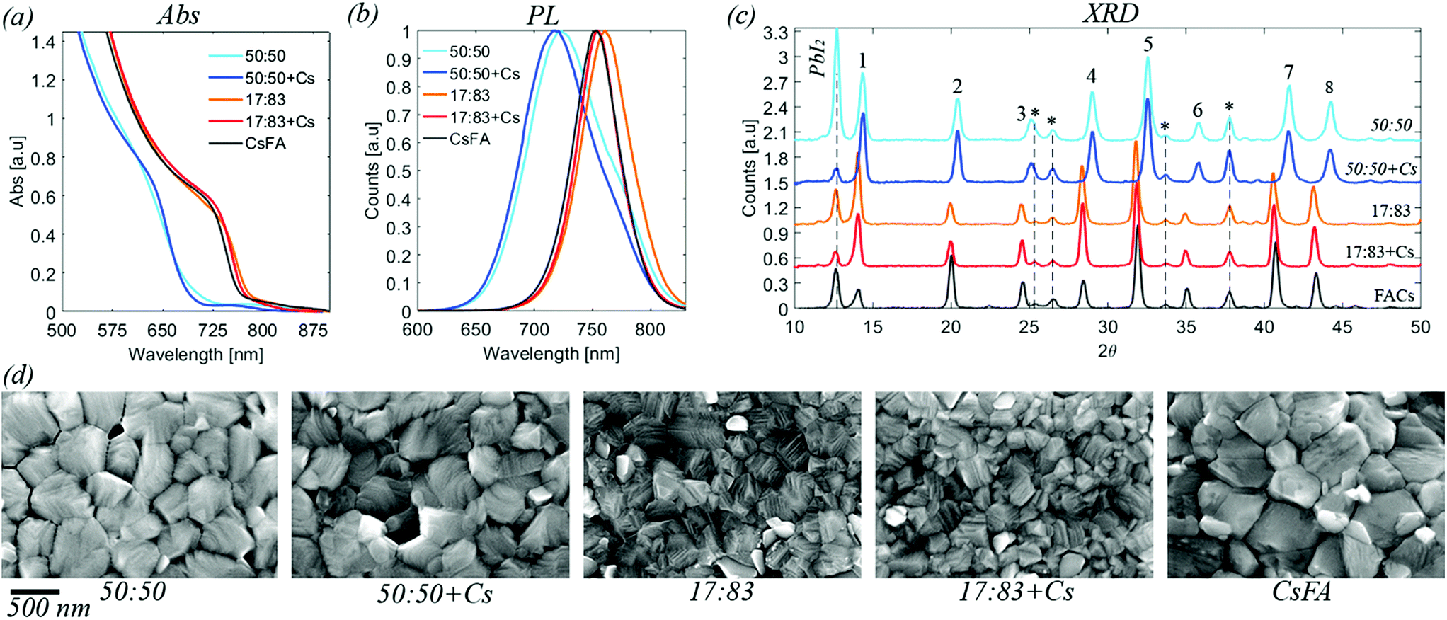 | ||
| Fig. 1 (a) UV-vis absorption for the five compositions investigated. Data is corrected for the background. Raw data is available in the ESI.† (b) Steady state photoluminescence. Normalised data. (c) X-ray diffraction data for perovskite films deposited on FTO/TiO2 substrates. The labelled peaks correspond to: 1 [001], 2 [011], 3 [111], 4 [002], 5 [012, 102], 6 [112], 7 [022], 8 [003, 112]. Peaks originating from the substrate are marked by * (d) top view SEM images for the five different compositions. Images at different resolution are available in the ESI.† | ||
The XRD diffractograms of the different perovskite compositions are presented in Fig. 1, S3 and S4.† For all samples, characteristic peaks of the perovskite structure are seen. Additionally, also some peaks of the FTO/TiO2 substrate are observed as well as the presence of PbI2. The presence of PbI2 is expected from the excess of PbI2 used in the sample preparation.41 The perovskite diffraction peak positions of the 17:83, 17:83 + Cs and CsFA samples are identical within the uncertainty suggesting that the cation only has a small effect on the unit cell of the perovskite. The diffraction peak positions of the 50:50 and 50:50 + Cs perovskites are shifted towards larger angles indicating that the unit cell is smaller than for 17:83, as would be expected with a higher bromide fraction. However, as for the 17:83 compositions, the difference in peak position between the 50:50 samples is negligible given the uncertainty.
SEM images of the different perovskite films are presented in Fig. 1 and S5 in the ESI.† The average crystal size of the 17:83, 17:83 + Cs is smaller than 50:50, 50:50 + Cs and the CsFA film. All the films are pinhole free. Devices were also manufactured and characterised, see Table S1 and Fig. S6,† using the studied compositions with top efficiencies of about 10% for the 50:50 compositions, 17% for the 17:83 compositions and 15% for the CsFA composition. All solar cells of the batch presented here showed hysteresis with the 50:50 compositions showing a larger hysteresis than the other compositions.
The results of the steady state PES characterisation of the different samples are presented in Fig. S7–S14 and Table S2 in the ESI.† Using intensity ratios corrected by the PbI2 and PbBr2 ratios, we found relatively similar I/Pb and Br/Pb intensity ratios with different photon energies and Table 2 presents these results as an average over the different photon energies. The ratios indicate that the surface is enriched in iodide in agreement with previous studies.41,52 The addition of Cs+ does not impact this with very similar Br:I intensity ratios found for the 83:17 and 83:17 + Cs and for the 50:50 and 50:50 + Cs sample surfaces. The CsFA sample shows a slightly lower I/Pb(II) ratio than the other two 83:17 samples and a significantly lower Br/Pb(II) ratio. However, all of the compositions show excess halides compared to what would be expected from a pure perovskite phase indicating that the surface is enriched in halides not associated with lead.
:I and MA:FA ratios compared with the theoretical ones. The MA:FA ratios are derived from the area of the fit of their respective N1s photoelectron signals with FA+ being weighted 1/2 of MA+ due to the presence of two nitrogen atoms in FA
| Sample | I/Pb(II) | Br/Pb(II) | Br:I ratio |
MA:FA ratio |
||||
|---|---|---|---|---|---|---|---|---|
| Experimental | Theoretical | Experimental | Theoretical | Experimental | Theoretical | Experimental | Theoretical | |
| 50:50 |
2.21 ± 0.07 | 1.50 | 1.63 ± 0.11 | 1.50 | 42:58 |
50:50 |
41:59 |
17:83 |
| 50:50 + Cs |
2.33 ± 0.11 | 1.50 | 1.65 ± 0.13 | 1.50 | 41:59 |
50:50 |
41:59 |
17:83 |
| 17:83 |
3.15 ± 0.20 | 2.49 | 0.42 ± 0.06 | 0.51 | 12:88 |
17:83 |
38:62 |
17:83 |
| 17:83 + Cs |
3.23 ± 0.17 | 2.49 | 0.43 ± 0.05 | 0.51 | 12:88 |
17:83 |
29:71 |
17:83 |
| CsFA | 3.00 ± 0.14 | 2.49 | 0.22 ± 0.05 | 0.51 | 7:93 |
17:83 |
— | — |
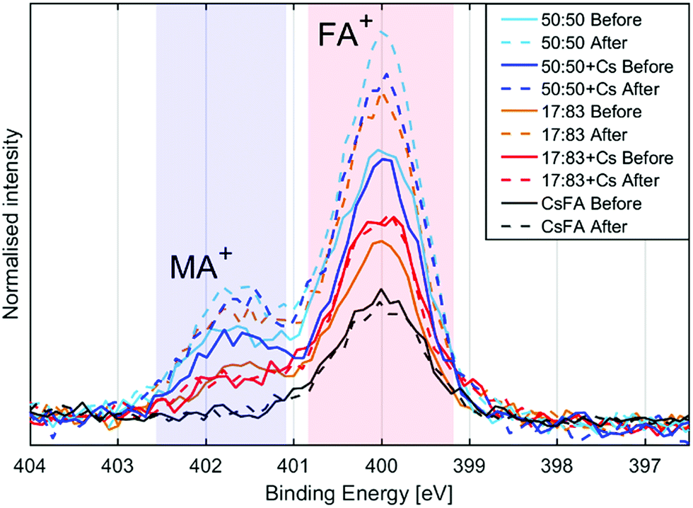
The presence of the organic cations can be investigated through the N1s spectra (Fig. 2a). While the absolute intensity ratios of the N1s in relation to Pb4f are difficult to assess due to their difference in kinetic energy (≈400 eV and ≈ 140 eV) and resulting difference in probing depth, we note that the 50:50 compositions show the highest N1s/Pb(II) intensity followed by the 17:83 compositions with CsFA showing a particularly low N1s/Pb(II) intensity (Fig. 2a). The N1s/Pb(II) intensity appears to correlate with excess halides indicating the presence of a surface layer of halides charge balanced by organic cations. The thickness and/or exact composition of this surface layer depends on the perovskite composition with a surface layer enriched in organic halide salts found for a 50:50 halide ratio. Fig. 2b shows a schematic representation of this result. Furthermore, the ratio of MA+ to FA+ can be assessed by comparing the ratios of the two different nitrogen peaks.41 We find that all samples show significantly more MA+ towards the surface than expected from stoichiometry. We also observe a signal of Cs4d in the 17:83 + Cs, 50:50 + Cs and CsFA samples (Fig. S10 and S12†) confirming the presence of Cs+ in the samples. However, due to the surface sensitivity of the measurement and the weakness of the signal, an accurate quantification of the Cs+ amounts was not possible in this case.
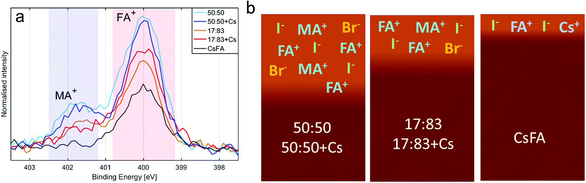 | ||
| Fig. 2 (a) The N1s spectra of the different compositions, normalised to Pb4f intensity and aligned to peak maximum at 400 eV. (b) Illustration of the surface structure of the different perovskite compositions. | ||
We now turn to the impact of laser illumination on the Pb5d, I4d and Br3d core levels. For all samples, the evolution of these levels was determined during illumination with a laser power of 0.20 mW, which approximately corresponds to a power density of 155 mW cm−2. The raw data of these measurements is presented as surface plots in the ESI (Fig. S15†). The general changes observed in the spectra are similar to our previous study:25 For all core levels, binding energy shifts to higher binding energies are observed during laser illumination. The main reason for these shifts is likely to be photo-induced charge separation between the perovskite films and the TiO2 substrate.25 Furthermore, during illumination of some of the samples we observe a change in intensity for the signal from Pb5d, I4d, and Br3d. For Pb5d, the formation of a new spin–orbit doublet associated with formation of metallic lead (Pb0) is observed in addition to intensity changes of the main peak. We therefore present the time evolution data through a comparison of the intensity changes in Pb5d, I4d and Br3d and the percentage of Pb0, which is formed in relation to the Pb(II) intensity (Fig. 3). For I4d and Br3d, the intensities are normalised to the initial I/Pb(II) and Br/Pb(II) ratios observed for each sample (from Table 2) in order to better indicate the absolute magnitudes of the changes. It is worth noting here again that none of the changes are induced by X-ray illumination but are due to the 515 nm laser illumination between t = 0 and t = 30 minutes.25
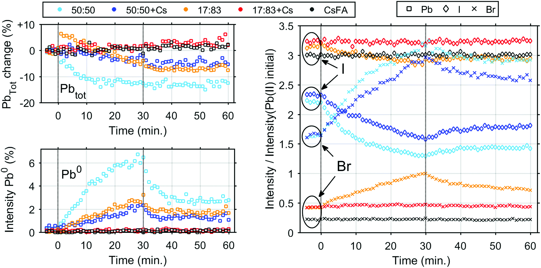 | ||
| Fig. 3 Intensity changes determined from core level spectroscopy of different perovskite samples before, during and after illumination with a 515 nm laser with an intensity of 0.20 mW. Vertical lines indicate when the laser was switched on and off at 0 and 30 minutes, respectively. Top left, evolution of total Pb concentration. Bottom left, fraction of Pb0. Right, evolution of I− (◊) and Br− (×). The initial value is set to their ratio towards Pb(II) as determined from steady-state characterisation. | ||
During illumination, we observed an increase in the surface (i.e. top 2 nm) concentration of Br− and a decrease in the concentration of I− for some of the samples, which is partially reversed after illumination. The magnitude of the change in I− and Br− concentration is highly dependent on their initial concentration in the sample. The largest final photo-induced changes are observed for the 50:50 sample followed by the 50:50 + Cs sample and finally the 17:83 sample. The 17:83 sample shows a step increase of total Pb intensity immediately after exposure to laser illumination. The origin of this step increase is unclear, as it was not observed in any of our other measurements.25 and could be an artefact from the measurement. Following this step increase, the total Pb intensity decreases as observed previously,25 however this decrease is not reversible. The 50:50 and 50:50 + Cs samples show a 13% and 5% irreversible decrease in total Pb intensity, respectively. In the 17:83 + Cs and CsFA samples, almost no light-induced changes are observed except for a small overall increase in the total Pb intensity. The Pb0 fraction follows a pattern similar to the one previously observed25 (except for the 17:83 + Cs and CsFA samples) with a continuous increase during illumination followed by a decrease after illumination to a constant value. Here, we observe that the 50:50 and 17:83 samples show a maximum Pb0 fraction of 6.1% and 2.7% and a post-illumination fraction of 3.3% and 1.7%, respectively. Interestingly, this is higher than for 50:50 + Cs which has a maximum Pb0 fraction of 2.2% and a post-illumination fraction of 1.3% suggesting that Cs could be more important for photostability than an optimal Br:I ratio, at least in regard to Pb0 formation. In case of the samples with a 17:83 ratio of Br to I and added Cs+, the Pb0 concentrations were below our detection limit (<0.3%) throughout the time evolution series.
In order to determine any differences in photostability between the 17:83 + Cs and CsFA samples, further measurements were carried out with a laser intensity of 0.91 mW (Fig. S16† and 4) which approximately corresponds to a power density of 706 mW cm−2. At this light intensity, both samples are still significantly more stable than the 17:83 sample. However, the formation of Pb0 is observed for the 17:83 + Cs sample (about 1% at the end of laser illumination), while the Pb0 intensity remains close to the detection limit for the CsFA sample. For both samples, the I− concentration remains constant while Br− increases slightly (more for the 17:83 + Cs sample).
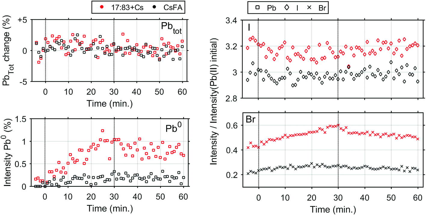 | ||
| Fig. 4 Intensity changes determined from core level spectroscopy of the 17:83 + Cs and CsFA perovskite samples before, during and after illumination with a 515 nm laser with an intensity of 0.91 mW. Vertical lines indicate when the laser was switched on and off at 0 and 30 minutes, respectively. Top left, evolution of total lead concentration. Bottom left, fraction of metallic lead. Right, evolution of I− (◊) and Br− (×). The initial value is set to their ratio towards Pb(II) as determined from steady-state characterisation. | ||
A further indication of the enhanced stability by the addition of Cs+ comes from the binding energy changes observed during and after laser illumination (Fig. 5 and S17†). In the initial stage of the laser illumination, similar binding energy shifts are observed for the different perovskites. However, after illumination the core levels of the changed perovskites (17:83, 50:50 and 50:50 + Cs) shift to lower binding energies than their original positions. This indicates either a change in the chemistry of the material or a shift in the Fermi level related to a change in the doping density. The formation of Pb0 could lead to an increased n-doping of the perovskite which should result in a Fermi level shift towards the conduction band and therefore a shift of core levels towards higher binding energies. This is not what we observe here and the shift of core levels to lower binding energies after illumination is instead consistent with an increased halide concentration at the surface after illumination due to ion migration. For the CsFA and 17:83 + Cs samples, core levels shift back to approximately their original binding energy with a laser intensity of 0.20 mW. For the CsFA sample, the core levels even shift back to values within 0.02 eV of their original positions after illumination with 0.91 mW, i.e. the shifts are reversible (Fig. S17†). This indicates that neither the Fermi level nor the chemistry of the CsFA sample has significantly been affected by illumination.
 | ||
| Fig. 5 The shifts in peak positions observed during illumination with 0.20 mW laser illumination relative to the original positions. From left to right, Pb5d, I4d and Br3d. Vertical lines indicate when the laser was switched on and off at 0 and 30 minutes, respectively. | ||
Steady state PES of sample spots illuminated with 0.20 mW was carried out after reaching equilibrium, i.e. when no more changes were observed. The results are compared to measurements on pristine sample spots (Table 3 and Fig. 6). The 50:50 samples show increases in the Br−/Pb(II) ratio and MA + FA/Pb(II) intensity while there is a decrease in the I/Pb(II) ratio. The magnitudes of the decrease of I/Pb(II) and the increase of MA + FA/Pb(II) intensity are similar for both 50:50 samples. The 17:83 sample shows an increase in I/Pb(II), Br/Pb(II) and MA + FA/Pb(II) intensity. An increase in I/Pb(II) ratio seems at first glance contradictory to the results presented in Fig. 3, where a decrease in absolute I4d intensity was observed during laser illumination. However, here a ratio to Pb(II) is shown and the decrease of Pb(II) intensity is not reversible while the decrease in I4d intensity is partially reversible (Fig. 3). The 17:83 + Cs and CsFA samples show no change in the I/Pb(II), Br/Pb(II) ratios and the MA + FA/Pb(+II) intensity. Finally, there appears to be a correlation between excess of halide, i.e. total halide/Pb(II) − 3, and the increase in organic cation to lead ratio (Fig. 6). This suggests that excess halides are charge balanced by MA + FA at the surface. The MA + FA and the halides most likely originate from the bulk of the perovskite. However, in all compositions the MA:FA ratio is unaffected by illumination indicating that MA and FA do not segregate during illumination. The relative increase in total halide and nitrogen intensities clearly demonstrate that the photo-induced changes observed here are not related to the degradation of the perovskites into PbI2 or PbBr2 and volatile degradation products of FA and MA. Such processes would occur, if the laser illumination caused a significant heating and heat-induced degradation of the samples.25 As discussed previously,25 our observed changes can instead be separated into two different types: a photo-induced electron transfer reaction, which results in the formation of Pb0, and ion migration, which results in concentration changes at the surface (Fig. 7). We have suggested that the formation of metallic lead occurs through the oxidation of iodide to iodine according to following the reaction
 :FA ratios are derived from the area of the fit of their respective N1s photoelectron signals with FA+ being weighted 1/2 of MA+
| Sample | I/Pb(II) | Br/Pb(II) | Excess Br + I/Pb(II) | Br:I ratio |
MA:FA ratio |
|
|---|---|---|---|---|---|---|
| 50:50 |
Before | 2.21 ± 0.07 | 1.63 ± 0.11 | 0.84 ± 0.13 | 42:58 |
41:59 |
| 50:50 |
After | 1.73 ± 0.03 | 2.71 ± 0.47 | 1.44 ± 0.47 | 61:39 |
41:59 |
| 50:50 + Cs |
Before | 2.33 ± 0.11 | 1.65 ± 0.13 | 0.97 ± 0.17 | 41:59 |
41:60 |
| 50:50 + Cs |
After | 2.01 ± 0.24 | 2.49 ± 0.43 | 1.51 ± 0.49 | 55:45 |
43:57 |
| 17:83 |
Before | 3.15 ± 0.20 | 0.42 ± 0.06 | 0.57 ± 0.21 | 12:88 |
38:62 |
| 17:83 |
After | 3.76 ± 0.05 | 0.81 ± 0.15 | 1.57 ± 0.16 | 18:82 |
41:59 |
| 17:83 + Cs |
Before | 3.23 ± 0.17 | 0.43 ± 0.04 | 0.66 ± 0.17 | 12:88 |
29:71 |
| 17:83 + Cs |
After | 3.25 ± 0.22 | 0.40 ± 0.05 | 0.65 ± 0.11 | 11:89 |
29:71 |
| CsFA | Before | 3.00 ± 0.14 | 0.22 ± 0.05 | 0.22 ± 0.15 | 7:93 |
— |
| CsFA | After | 3.01 ± 0.07 | 0.23 ± 0.02 | 0.24 ± 0.07 | 7:93 |
— |
 | ||
| Fig. 6 N1s spectra of the different compositions before and after illumination, normalised to Pb(+II) 4f intensity and aligned with peak maximum at 400 eV. | ||
 | ||
| Fig. 7 (a) Illustration of the degradation and ion migration during illumination: formation of Pb0 with some I2 products escaping to vacuum, migration of halides and organic cations adding to the surface layer. (b) Recovery processes after illumination: formation of perovskite from Pb0, exchange of halides between surface layer and perovskite. (c) The protective mechanism of Cs+ at optimum Br:I ratio: blocking the formation of Pb0 and I2 and blocking halide and organic cation migration. | ||
However, Pb0 formation itself cannot explain the changes in the Br:I ratio and the overall increase in halide concentration at the sample surfaces that we observe in some of our samples. Instead, as reported previously,25 the most likely explanation for the intensity change is related to ion movements and phase separation of the perovskite into a Br-rich and a I-rich phase with the Br-rich phase being preferential to the surface. Phase separation has been observed for mixed halide compositions containing more than 20% bromide for MA and FA cations.32,37 Photoluminescence studies point to the I-rich phase having a Br:I ratio about 20:80 in samples where phase separation occurs regardless of the original composition31,32,34,35,54 as well as indicating that the I-rich phase tends to accumulate in the grain boundaries.55 For our 17:83 samples, phase separation is not expected to occur, but we clearly observe ion migration and the formation of a bromide-rich phase at the surface in absence of Cs+. For the 50:50 samples, illumination also leads to a bromide-rich phase at the sample surface that is enriched with Br− and depleted in I− during illumination. This suggests that the surface might behave differently from the grain boundaries. The time scales observed here for the concentration changes at the surface are different to time scales observed in XRD studies of MA-based perovskites where phase separation took less than 1 minute, compared to changes occurring for 30 minutes in our results.31,34,35 This could suggest that we observe some slower changes at the surface of the films than XRD does for the bulk.
It is clear from our results that both the observation of ion movement/phase segregation and Pb0 formation at the sample surface are strongly affected by the addition of Cs+ ions to the perovskite composition (Fig. 7c). In the case of the samples with a 50:50 Br:I ratio, it is mostly the Pb0 formation which is diminished by the presence of Cs+, while ion migration clearly still occurs although at a reduced rate. For the 17:83 samples, the addition of Cs+ makes the sample surfaces significantly more stable both in terms of Pb0 formation and ion movement/phase separation. One potential explanation is improved crystallinity and a decrease in defect density by the addition of Cs+.24,56 Defects are expected to play an important role for ion migration in perovskites57 with the grain boundaries being particularly sensitive,58,59 as it is likely that the mobile halides are vacancies and interstitials. Fewer defects and a decreased mobility of halide ions can also explain a decrease in the amount of metallic lead formed: as discussed above formation of molecular iodine is likely to involve iodine interstitials and require mobile iodine. A reduction in the defect density could therefore be the reason for the reduced ion migration and also for the reduced formation of Pb0, we observe upon addition of Cs+ at an optimal Br:I ratio. Decreased phase separation with Cs+ and FA+ has also been explained by reduced lattice distortions caused by excited carriers, which should lead to a thermodynamic favouring of a uniform phase.32 Recently, Bischak et al. linked the formation and stabilisation of iodide-rich clusters in mixed-halide single crystal perovskites to strong electron-phonon coupling, which could be limited by substituting polar cations (MA) with non-polar cations (Cs+).60 Regardless of the mechanism it is generally agreed that Cs+ decreases the tendency for phase separation.29,30,56,61 Our results clearly show that addition of Cs+ can limit ion migration. It is therefore possible to significantly increase the intrinsic photo-stability of lead halides perovskites by optimising the A-site cation composition and the Br:I ratio.
Conclusions
In this study, we have used photoelectron spectroscopy to study photo-induced chemical changes in perovskites with 5 different compositions (FA0.83MA0.17Pb(Br0.17I0.83)3, Cs0.05FA0.79MA0.16Pb(Br0.17I0.83)3, FA0.83MA0.17Pb(Br0.5I0.5)3, Cs0.05FA0.79MA0.16Pb(Br0.5I0.5)3 and Cs0.17FA0.83Pb(Br0.17I0.83)3) during illumination with a 515 nm laser. Our measurements directly reflect on the photo-stability of the different perovskite compositions through monitoring chemical changes at the sample surface. During illumination, we observe the formation of metallic lead (Pb0), a decrease of the total Pb and I− concentration, and an increase of the Br− concentration for some of the samples. The formation of metallic lead can be related to a photo-induced electron transfer reaction in which iodide is the electron donor. This reaction can be reversible in the dark if iodine is not removed from the sample. The changes in bromide and iodide concentration reflect ion movement in the material and could be related to phase separation. The photostability was enhanced by a Br:I ratio of 17:83 compared to 50:50 in agreement with other studies. We found that the addition of Cs+ stabilised the 17:83 composition by preventing ion migration and the formation of metallic lead. At the 50:50 composition, ion migration is not prevented by the addition of Cs+ but Pb0 formation is significantly reduced. This indicates that optimising the A-site cation composition could be a viable way for stabilising the more bromide rich perovskites interesting for tandem applications. Furthermore, we are able to show that the replacement of MA+ with Cs+ appears to further increase the stability compared to the most common 17:83 perovskites with 5% added Cs+. We also observe that the total amount of halides and organic cations at the surface increases after illumination for the unstable 50:50, 50:50 + Cs and 17:83 samples. However, the MA:FA ratio is unaffected by illumination. Together with photochemical changes, we observed core level shifts to lower binding energies following illumination. This shows that degradation affects the electronic structure of the perovskites, either due to changes in the chemical composition of the material or a reduced n-doping at the surface leading to a Fermi level shift relative to the valence band. Our study therefore gives clear insight into changes occurring in lead halide perovskites under illumination. In the future, such studies can be extended to further perovskite compositions. Furthermore, different surface treatments of the perovskites films prior to illumination could be included. Finally, our methodology is also applicable for stability studies of other materials of relevance for optoelectronic applications.
Conflicts of interest
There are no conflicts of interest.Acknowledgements
We acknowledge research funding from the Swedish Research Council (project no. 2014-6019), the Åforsk foundation, the Swedish Foundation for Strategic Research (project no. RMA15-0130), the Swedish Energy Agency (project no. P43294-1) and the StandUP for Energy program. We thank HZB for the allocation of synchrotron radiation beamtime.References
- A. Kojima, K. Teshima, Y. Shirai and T. Miyasaka, J. Am. Chem. Soc., 2009, 131, 6050–6051 CrossRef PubMed.
- N. Arora, M. I. Dar, A. Hinderhofer, N. Pellet, F. Schreiber, S. M. Zakeeruddin and M. Grätzel, Science, 2017, eaam5655 Search PubMed.
- M. Saliba, T. Matsui, J.-Y. Seo, K. Domanski, J.-P. Correa-Baena, M. Khaja Nazeeruddin, S. M. Zakeeruddin, W. Tress, A. Abate, A. Hagfeldt and M. Grätzel, Energy Environ. Sci., 2016, 9, 1989–1997 RSC.
- X. Li, M. Tschumi, H. Han, S. S. Babkair, R. A. Alzubaydi, A. A. Ansari, S. S. Habib, M. K. Nazeeruddin, S. M. Zakeeruddin and M. Grätzel, Energy Technol., 2015, 3, 551–555 CrossRef.
- W. S. Yang, B.-W. Park, E. H. Jung, N. J. Jeon, Y. C. Kim, D. U. Lee, S. S. Shin, J. Seo, E. K. Kim and J. H. Noh, Science, 2017, 356, 1376–1379 CrossRef PubMed.
- J.-P. Correa-Baena, A. Abate, M. Saliba, W. Tress, T. Jesper Jacobsson, M. Grätzel and A. Hagfeldt, Energy Environ. Sci., 2017, 10, 710–727 RSC.
- NREL, Best Research-Cell Efficiencies, https://www.nrel.gov/pv/assets/images/efficiency-chart.png, accessed 4 May 2018.
- K. Sveinbjörnsson, N. K. Kyi Thein, Z. Saki, S. Svanström, W. Yang, U. B. Cappel, H. Rensmo, G. Boschloo, K. Aitola and E. M. J. Johansson, Sustainable Energy Fuels, 2018, 2, 606–615 RSC.
- W.-J. Yin, T. Shi and Y. Yan, Appl. Phys. Lett., 2014, 104, 063903 CrossRef.
- T. Jesper Jacobsson, J.-P. Correa-Baena, M. Pazoki, M. Saliba, K. Schenk, M. Grätzel and A. Hagfeldt, Energy Environ. Sci., 2016, 9, 1706–1724 RSC.
- B. Park, B. Philippe, S. M. Jain, X. Zhang, T. Edvinsson, H. Rensmo, B. Zietz and G. Boschloo, J. Mater. Chem. A, 2015, 3, 21760–21771 RSC.
- D. Bryant, N. Aristidou, S. Pont, I. Sanchez-Molina, T. Chotchunangatchaval, S. Wheeler, J. R. Durrant and S. A. Haque, Energy Environ. Sci., 2016, 9, 1655–1660 RSC.
- Y. Han, S. Meyer, Y. Dkhissi, K. Weber, J. M. Pringle, U. Bach, L. Spiccia and Y.-B. Cheng, J. Mater. Chem. A, 2015, 3, 8139–8147 RSC.
- C.-J. Tong, W. Geng, Z.-K. Tang, C.-Y. Yam, X.-L. Fan, J. Liu, W.-M. Lau and L.-M. Liu, J. Phys. Chem. Lett., 2015, 6, 3289–3295 CrossRef.
- G. Divitini, S. Cacovich, F. Matteocci, L. Cinà, A. D. Carlo and C. Ducati, Nat. Energy, 2016, 1, 15012 CrossRef.
- S.-W. Lee, S. Kim, S. Bae, K. Cho, T. Chung, L. E. Mundt, S. Lee, S. Park, H. Park, M. C. Schubert, S. W. Glunz, Y. Ko, Y. Jun, Y. Kang, H.-S. Lee and D. Kim, Sci. Rep., 2016, 6, 38150 CrossRef PubMed.
- B. Chen, M. Yang, S. Priya and K. Zhu, J. Phys. Chem. Lett., 2016, 7, 905–917 CrossRef PubMed.
- W. Tress, N. Marinova, T. Moehl, S. M. Zakeeruddin, M. K. Nazeeruddin and M. Grätzel, Energy Environ. Sci., 2015, 8, 995–1004 RSC.
- Y. Zhang, M. Liu, G. E. Eperon, T. C. Leijtens, D. McMeekin, M. Saliba, W. Zhang, M. de Bastiani, A. Petrozza, L. M. Herz, M. B. Johnston, H. Lin and H. J. Snaith, Mater. Horiz., 2015, 2, 315–322 RSC.
- R. E. Beal, D. J. Slotcavage, T. Leijtens, A. R. Bowring, R. A. Belisle, W. H. Nguyen, G. F. Burkhard, E. T. Hoke and M. D. McGehee, J. Phys. Chem. Lett., 2016, 7, 746–751 CrossRef PubMed.
- H. Choi, J. Jeong, H.-B. Kim, S. Kim, B. Walker, G.-H. Kim and J. Y. Kim, Nano Energy, 2014, 7, 80–85 CrossRef.
- T. Singh and T. Miyasaka, Adv. Energy Mater., 2018, 8, 1700677 CrossRef.
- Q. Fu, X. Tang, B. Huang, T. Hu, L. Tan, L. Chen and Y. Chen, Adv. Sci., 2018, 5, 1700387 CrossRef PubMed.
- Y. Hu, E. M. Hutter, P. Rieder, I. Grill, J. Hanisch, M. F. Aygüler, A. G. Hufnagel, M. Handloser, T. Bein, A. Hartschuh, K. Tvingstedt, V. Dyakonov, A. Baumann, T. J. Savenije, M. L. Petrus and P. Docampo, Adv. Energy Mater., 2018, 1703057 CrossRef.
- U. B. Cappel, S. Svanström, V. Lanzilotto, F. O. L. Johansson, K. Aitola, B. Philippe, E. Giangrisostomi, R. Ovsyannikov, T. Leitner, A. Föhlisch, S. Svensson, N. Mårtensson, G. Boschloo, A. Lindblad and H. Rensmo, ACS Appl. Mater. Interfaces, 2017, 9, 34970–34978 CrossRef PubMed.
- E. Giangrisostomi, R. Ovsyannikov, F. Sorgenfrei, T. Zhang, A. Lindblad, Y. Sassa, U. B. Cappel, T. Leitner, R. Mitzner, S. Svensson, N. Mårtensson and A. Föhlisch, J. Electron Spectrosc. Relat. Phenom., 2018, 224, 68–78 CrossRef.
- M. Saliba, T. Matsui, K. Domanski, J.-Y. Seo, A. Ummadisingu, S. M. Zakeeruddin, J.-P. Correa-Baena, W. R. Tress, A. Abate, A. Hagfeldt and M. Grätzel, Science, 2016, 354, 206–209 CrossRef PubMed.
- D. Bi, W. Tress, M. I. Dar, P. Gao, J. Luo, C. Renevier, K. Schenk, A. Abate, F. Giordano, J.-P. Correa Baena, J.-D. Decoppet, S. M. Zakeeruddin, M. K. Nazeeruddin, M. Gra tzel and A. Hagfeldt, Sci. Adv., 2016, 2, e1501170 Search PubMed.
- I. L. Braly, R. J. Stoddard, A. Rajagopal, A. R. Uhl, J. K. Katahara, A. K.-Y. Jen and H. W. Hillhouse, ACS Energy Lett., 2017, 2, 1841–1847 CrossRef.
- D. P. McMeekin, G. Sadoughi, W. Rehman, G. E. Eperon, M. Saliba, M. T. Hörantner, A. Haghighirad, N. Sakai, L. Korte and B. Rech, Science, 2016, 351, 151–155 CrossRef PubMed.
- E. T. Hoke, D. J. Slotcavage, E. R. Dohner, A. R. Bowring, H. I. Karunadasa and M. D. McGehee, Chem. Sci., 2015, 6, 613–617 RSC.
- D. J. Slotcavage, H. I. Karunadasa and M. D. McGehee, ACS Energy Lett., 2016, 1, 1199–1205 CrossRef.
- M. C. Brennan, S. Draguta, P. V. Kamat and M. Kuno, ACS Energy Lett., 2018, 3, 204–213 CrossRef.
- S. J. Yoon, S. Draguta, J. S. Manser, O. Sharia, W. F. Schneider, M. Kuno and P. V. Kamat, ACS Energy Lett., 2016, 1, 290–296 CrossRef.
- X. Yang, X. Yan, W. Wang, X. Zhu, H. Li, W. Ma and C. Sheng, Org. Electron., 2016, 34, 79–83 CrossRef.
- T. Duong, H. K. Mulmudi, Y. Wu, X. Fu, H. Shen, J. Peng, N. Wu, H. T. Nguyen, D. Macdonald, M. Lockrey, T. P. White, K. Weber and K. Catchpole, ACS Appl. Mater. Interfaces, 2017, 9, 26859–26866 CrossRef PubMed.
- E. L. Unger, L. Kegelmann, K. Suchan, D. Sörell, L. Korte and S. Albrecht, J. Mater. Chem. A, 2017, 5, 11401–11409 RSC.
- T. Singh, S. Öz, A. Sasinska, R. Frohnhoven, S. Mathur and T. Miyasaka, Adv. Funct. Mater., 2018, 28, 1706287 CrossRef.
- Y. Wang, J. Wu, P. Zhang, D. Liu, T. Zhang, L. Ji, X. Gu, Z. David Chen and S. Li, Nano Energy, 2017, 39, 616–625 CrossRef.
- K. A. Bush, A. F. Palmstrom, Z. J. Yu, M. Boccard, R. Cheacharoen, J. P. Mailoa, D. P. McMeekin, R. L. Z. Hoye, C. D. Bailie, T. Leijtens, I. M. Peters, M. C. Minichetti, N. Rolston, R. Prasanna, S. Sofia, D. Harwood, W. Ma, F. Moghadam, H. J. Snaith, T. Buonassisi, Z. C. Holman, S. F. Bent and M. D. McGehee, Nat. Energy, 2017, 2, 17009 CrossRef.
- T. J. Jacobsson, J.-P. Correa-Baena, E. Halvani Anaraki, B. Philippe, S. D. Stranks, M. E. F. Bouduban, W. Tress, K. Schenk, J. Teuscher, J.-E. Moser, H. Rensmo and A. Hagfeldt, J. Am. Chem. Soc., 2016, 138, 10331–10343 CrossRef PubMed.
- R. Ovsyannikov, P. Karlsson, M. Lundqvist, C. Lupulescu, W. Eberhardt, A. Föhlisch, S. Svensson and N. Mårtensson, J. Electron Spectrosc. Relat. Phenom., 2013, 191, 92–103 CrossRef.
- B. Philippe, T. J. Jacobsson, J.-P. Correa-Baena, N. K. Jena, A. Banerjee, S. Chakraborty, U. B. Cappel, R. Ahuja, A. Hagfeldt, M. Odelius and H. Rensmo, J. Phys. Chem. C, 2017, 121, 26655–26666 CrossRef.
- B. Philippe, B.-W. Park, R. Lindblad, J. Oscarsson, S. Ahmadi, E. M. J. Johansson and H. Rensmo, Chem. Mater., 2015, 27, 1720–1731 CrossRef.
- S. Tanuma, C. J. Powell and D. R. Penn, Surf. Interface Anal., 2003, 35, 268–275 CrossRef.
- Y. Yuan, Q. Wang, Y. Shao, H. Lu, T. Li, A. Gruverman and J. Huang, Adv. Energy Mater., 2016, 6, 1501803 CrossRef.
- D. A. Shirley, Phys. Rev. B, 1972, 5, 4709 CrossRef.
- A. Herrera-Gomez, M. Bravo-Sanchez, O. Ceballos-Sanchez and M. O. Vazquez-Lepe, Surf. Interface Anal., 2014, 46, 897–905 CrossRef.
- A. Herrera-Gomez, M. Bravo-Sanchez, F. S. Aguirre-Tostado and M. O. Vazquez-Lepe, J. Electron Spectrosc. Relat. Phenom., 2013, 189, 76–80 CrossRef.
- J. H. Shofield, Theoretical photoionization cross sections from 1 to 1500 keV, Lawrence Livermore Lab, California University, Livermore, 1973, vol. no. UCRL–51326 Search PubMed.
- J. J. Yeh and I. Lindau, At. Data Nucl. Data Tables, 1985, 32, 1–155 CrossRef.
- B. Philippe, M. Saliba, J.-P. Correa-Baena, U. B. Cappel, S.-H. Turren-Cruz, M. Grätzel, A. Hagfeldt and H. Rensmo, Chem. Mater., 2017, 29, 3589–3596 CrossRef.
- G. Y. Kim, A. Senocrate, T.-Y. Yang, G. Gregori, M. Grätzel and J. Maier, Nat. Mater., 2018, 17, 445–449 CrossRef PubMed.
- G. F. Samu, C. Janáky and P. V. Kamat, ACS Energy Lett., 2017, 2, 1860–1861 CrossRef.
- C. G. Bischak, C. L. Hetherington, H. Wu, S. Aloni, D. F. Ogletree, D. T. Limmer and N. S. Ginsberg, Nano Lett., 2017, 17, 1028–1033 CrossRef PubMed.
- W. Rehman, D. P. McMeekin, J. B. Patel, R. L. Milot, M. B. Johnston, H. J. Snaith and L. M. Herz, Energy Environ. Sci., 2017, 10, 361–369 RSC.
- J. M. Azpiroz, E. Mosconi, J. Bisquert and F. De Angelis, Energy Environ. Sci., 2015, 8, 2118–2127 RSC.
- Y. Shao, Y. Fang, T. Li, Q. Wang, Q. Dong, Y. Deng, Y. Yuan, H. Wei, M. Wang, A. Gruverman, J. Shield and J. Huang, Energy Environ. Sci., 2016, 9, 1752–1759 RSC.
- J. Xing, Q. Wang, Q. Dong, Y. Yuan, Y. Fang and J. Huang, Phys. Chem. Chem. Phys., 2016, 18, 30484–30490 RSC.
- C. G. Bischak, A. B. Wong, E. Lin, D. T. Limmer, P. Yang and N. S. Ginsberg, J. Phys. Chem. Lett., 2018, 3998–4005 CrossRef PubMed.
- R. J. Stoddard, F. T. Eickemeyer, J. K. Katahara and H. W. Hillhouse, J. Phys. Chem. Lett., 2017, 8, 3289–3298 CrossRef PubMed.
Footnote |
| † Electronic supplementary information (ESI) available: Detailed sample preparation and device fabrication. UV-vis and photoluminescence (PL) measurement of films compositions. XRD measurements of film compositions and the FTO/TiO2 substrate. SEM images of film compositions at different magnifications. Device characterisation of devices fabricated using the different film compositions. Steady state photoelectron spectra of the N1s, Pb4f, Br3d, I4d and Pb5d of PbI2, PbBr2 and film compositions. Characterisation derived from said spectra. Surface plots of Br3d, I4d and Pb5d core levels during illumination as well as shift in these core levels. See DOI: 10.1039/c8ta05795h |
| This journal is © The Royal Society of Chemistry 2018 |