 Open Access Article
Creative Commons Attribution 3.0 Unported Licence
NASICON LiM2(PO4)3 electrolyte (M = Zr) and electrode (M = Ti) materials for all solid-state Li-ion batteries with high total conductivity and low interfacial resistance†
Hany
El-Shinawi
 a,
Anna
Regoutz
 b,
David J.
Payne
 b,
Edmund J.
Cussen
 *c and
Serena A.
Corr
 *a
*a
aSchool of Chemistry, WestCHEM, University of Glasgow, Glasgow G12 8QQ, UK. E-mail: serena.corr@glasgow.ac.uk
bDepartment of Materials, Imperial College London, Exhibition Road, London SW7 2AZ, UK
cDepartment of Pure and Applied Chemistry, WestCHEM, The University of Strathclyde, Glasgow, G1 1XL, UK. E-mail: edmund.cussen@strath.ac.uk
First published on 23rd January 2018
Abstract
All solid-state batteries based on NASICON-type LiM2(PO4)3 electrolyte phases are highly promising owing to their high ionic conductivities and chemical stabilities. Unlike Ti-based phases, extensively studied as Li+ solid electrolyte membranes, LiZr2(PO4)3 (LZP) is expected to form a stable interface with a metallic lithium anode, a challenge which has posed a serious roadblock to realising safe all solid-state batteries. However, prohibitively large grain boundary resistances are often observed in this material and this issue, combined with processing difficulties in fabricating LZP in dense forms, has impinged on the application of LZP as a solid electrolyte for all solid-state batteries. To overcome these shortcomings and demonstrate the excellent potential of LZP as a solid electrolyte, we have developed a simple approach, based on sol–gel chemistry, to effectively improve the densification of the material leading to higher total conductivity than previously reported (1.0 × 10⁻⁴ S cm−1 at 80 °C) and enabling the investigation of the material as a Li+ solid electrolyte without the need for elaborate post-processing steps. The interfacial resistance decreases dramatically on using thin layers of Au buffer to improve the contact between Li and the LZP surface. The Li/LZP interface shows constant resistance upon Li+ cycling (at 40 μA cm−2), despite the formation of a passivation layer of Li3P/Li8ZrO6 on the LZP surface. This is consistent with the prediction that this surface layer serves as a Li+ conductive, solid electrolyte interface between Li and LZP. Finally, an analogue material, LiTi2(PO4)3, is also introduced and demonstrated as an electrode material for proposed LZP-based all-solid-state batteries.
Introduction
Ti and Ge-based NASICON-type phases such as Li1.3Ti1.7Al0.3(PO4)3 (LATP) and Li1.5Ge1.5Al0.5(PO4)3 (LAGP) possess high Li+ conductivities at room temperature (up to 1 × 10⁻³ S cm−1)1,2 and are widely investigated as Li+ solid electrolyte membranes. Unlike lithium stuffed garnets (e.g. Li7La3Zr2O12), these phases are stable in air and in water.3 LATP and LAGP are, however, unstable in contact with Li metal due to reduction of Ti4+ and Ge4+, hindering their use in battery configurations which require direct contact with lithium anodes.4 The switch to the “predictably” more stable LiZr2(PO4)3 (LZP) is, however, impeded by the complex polymorphism of the material and its low affinity toward doping.5–11 Unlike LAGP and LATP, it is also (to date) not possible to prepare LZP by conventional melt-quenching methods that yield the kind of dense ceramics required for use in applications which demand high ionic conductivities. This significantly precludes the application of LZP as a Li+ solid electrolyte since, apart from recently reported spark plasma sintering methods,12 the material is not sufficiently sintered using conventional methodologies. A compelling first step toward investigating LZP as a potential Li+ solid electrolyte would be to fabricate suitably dense phases using a consistent procedure. In this paper, we describe a simple approach to achieve this based on sol–gel chemistry. We also demonstrate the use of this sintered electrolyte in combination with a Li metal anode and also a preliminary investigation of an all NASICON-phase all solid-state battery comprising Li/LZP/LTP, where LTP is a LiTi2(PO4)3 cathode.Two main polymorphs of LZP can be accessed depending on the synthesis temperature; namely, β and α-type phases. β-type phases, prepared at ∼900 °C, are orthorhombic above 300 °C and monoclinic with a β-Fe2(SO4)3-type structure below this temperature.6 α-type phases, prepared at higher calcination temperatures (∼1200 °C), on the other hand, are rhombohedral above a transition temperature varying in the range of 20 °C to 60 °C.5,7–9 Despite the complex polymorphism of LZP, it is generally found that the material has a bulk conductivity greater than 1 × 10⁻⁴ S cm−1 when the rhombohedral α-phase is stabilized.9,12 The challenge is therefore to stabilize the rhombohedral α-phase in a suitably dense form to obtain relatively high total conductivities. Very recently Li et al. have used spark plasma sintering to obtain dense ceramics.12 Here, we describe a simple synthetic procedure which can be easily reproduced and replicated that results in relatively dense ceramics with total conductivities comparable to those of the spark plasma sintered phases. We have also examined the Li/LZP and LTP/LZP interfaces for all-solid-state battery applications, showing excellent compatibility between LTP and LZP and confirming the formation of a low-resistive solid electrolyte interface (SEI) layer between Li and LZP upon Li+ cycling.
Experimental
Synthesis
LZP and Ca-doped LZP (LZP-Ca) phases are prepared by a modified sol–gel approach.9 Typically, solid citric acid and EDTA (dissolved in NH3 solution) were added to a solution containing stoichiometric amounts of lithium acetate (99.95%) and zirconium oxynitrate hydrate (99%) in dilute nitric acid. The molar ratio of total metal ions to EDTA and to citrate was 1![[thin space (1/6-em)]](https://www.rsc.org/images/entities/char_2009.gif) :
:![[thin space (1/6-em)]](https://www.rsc.org/images/entities/char_2009.gif) 1
1![[thin space (1/6-em)]](https://www.rsc.org/images/entities/char_2009.gif) :
:![[thin space (1/6-em)]](https://www.rsc.org/images/entities/char_2009.gif) 2. Dilute NH3 solution was used to adjust the pH value of the solution to a value >7, then few drops of H2O2 and a stoichiometric amount of NH4H2PO4 (≥98.0%) were added to the mixture. The resulting clear solution was evaporated at ∼110 °C to form a transparent gel, which was dried and burnt in air at 550 °C for 12 h. The resulting solid precursor is pressed into pellets and calcined for 50 min at 1100 °C, followed by quenching to room temperature. LTP is synthesized by the procedure described in ref. 13.
2. Dilute NH3 solution was used to adjust the pH value of the solution to a value >7, then few drops of H2O2 and a stoichiometric amount of NH4H2PO4 (≥98.0%) were added to the mixture. The resulting clear solution was evaporated at ∼110 °C to form a transparent gel, which was dried and burnt in air at 550 °C for 12 h. The resulting solid precursor is pressed into pellets and calcined for 50 min at 1100 °C, followed by quenching to room temperature. LTP is synthesized by the procedure described in ref. 13.
Characterization
X-ray diffraction (XRD) analysis was performed using a PANalytical X'Pert PRO diffractometer in reflection mode using Cu-Kα radiation. Scanning electron microscopy (SEM) studies were performed using Carl Zeiss Sigma variable pressure analytical electron microscope. The machine is equipped with an angle selective backscattered electron detector (AsB), to obtain a materials contrast image. X-ray photoelectron spectroscopy (XPS) analysis was performed using a Thermo Scientific K-Alpha + X-ray Photoelectron Spectrometer system operating at a base pressure of 2 × 10⁻⁹ mbar. This system incorporates a monochromated, microfocused Al Kα X-ray source (hν = 1486.6 eV), which was operated a 6 mA emission current and 12 kV anode bias. The system includes a 180° double focusing hemispherical analyser coupled with a 2D detector. Data were collected at 200 eV pass energy for survey and 20 eV pass energy for core level spectra using an X-ray spot size of 400 μm. A flood gun was used to minimize sample charging. Spectra were aligned assuming the C 1s core line to be at a binding energy of 285.0 eV. All data were analysed using the Avantage software package.AC impedance measurements were recorded using a Solartron 1260 impedance analyser and a BioLogic VSP potentiostat in the frequency range of 1 MHz to 1 Hz with an electrical perturbation of 50 mV. As-prepared pellets were polished by SiC sandpaper up to 1200 grit to ensure flat surfaces before use. The thickness of the pellets was 1.4–1.5 mm, and the area of the electrodes was 0.5 or 0.636 cm2. For measurements with Au electrodes, Au was gas-phase deposited onto both sides of the pellet by thermal evaporation. For measurements with lithium electrodes, cells were prepared in an Ar-filled glovebox where pellets were sandwiched between two lithium foils (Sigma Aldrich, 0.38 mm) in Swagelok cells using stainless steel current collectors. The surfaces of the used lithium foils were scratched using a stainless steel blade to obtain fresh surfaces before use. Prior to each measurement, the cell was equilibrated at the desired temperature (50 or 80 °C) for 2 hours. No prior heat treatments were performed, e.g. to improve the contact between LZP and Li. For samples with Au buffer layers, thin layers of Au were sputtered onto both sides of the pellets by using a sputter coater (Polaron SC7640). The sputtering time was 20 s, using 20 mA sputtering current and an Ar pressure of ∼0.02 mbar. The constant current galvanostatic cycling was performed using a BioLogic VSP potentiostat by applying a constant current for 2 h, followed by a 10 min OCV before switching to the opposing current direction.
Li/LZP/LTP solid-state cell
A slurry containing LTP and PVDF binder (80![[thin space (1/6-em)]](https://www.rsc.org/images/entities/char_2009.gif) :
:![[thin space (1/6-em)]](https://www.rsc.org/images/entities/char_2009.gif) 20 wt%) in NMP is used to prepare the LTP electrode. The LTP slurry is coated on one side of the LZP pellet, dried at 50 °C, and the pellet is heated slowly to 350 °C (∼2 °C min−1), and then fired to 1100 °C at 10 °C min−1. After 10 minutes sintering the sample is quenched to room temperature. An Au layer is then gas-phase deposited on top of LTP to collect the current from the cathode. A thin Au buffer layer is then deposited on the bare side of the pellet followed by attaching Li to this side as the negative electrode in an Ar-filled glovebox. A Swagelok cell with stainless steel current collectors is used to contain the battery.
20 wt%) in NMP is used to prepare the LTP electrode. The LTP slurry is coated on one side of the LZP pellet, dried at 50 °C, and the pellet is heated slowly to 350 °C (∼2 °C min−1), and then fired to 1100 °C at 10 °C min−1. After 10 minutes sintering the sample is quenched to room temperature. An Au layer is then gas-phase deposited on top of LTP to collect the current from the cathode. A thin Au buffer layer is then deposited on the bare side of the pellet followed by attaching Li to this side as the negative electrode in an Ar-filled glovebox. A Swagelok cell with stainless steel current collectors is used to contain the battery.
Results and discussion
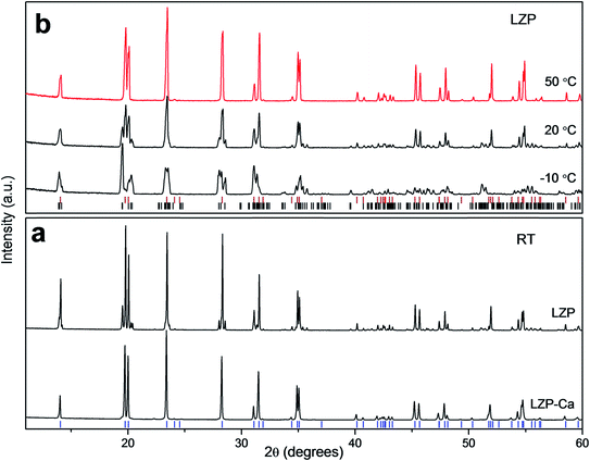
Previous work has shown that a sol–gel synthesis can yield rhombohedral LZP at 1200 °C.9 In the current work, we have adapted this kind of approach and quenched the material from 1100 °C, after a short sintering time (50 min, sample LZP-1100). Interestingly and rather unexpectedly, relatively dense ceramics were obtained using this simple procedure. A powder XRD study of the material obtained revealed a mixture of triclinic and rhombohedral LZP, with the rhombohedral phase predominating (Fig. 1a). Importantly, the material displayed a reversible phase change to pure rhombohedral LZP at ∼50 °C, with no apparent effect on the material hardness or sinterability. Fig. 1b shows the XRD patterns of LZP-1100 at selected temperatures and indicates that a pure rhombohedral LZP is formed at 50 °C. Repeated impedance spectroscopy measurements at temperatures ≥50 °C (Fig. S1†), obtained by cooling to room temperature and storing in air, showed a small change in the impedance which indicates an effective retention of the sinterability. We attribute the preservation of the sinterability upon heating and cooling to the predominance of the rhombohedral phase (∼83 wt%, as indicated by XRD data refinement; Fig. S2†). For the sake of comparison, we employed the same synthetic procedure to prepare Ca-doped LZP (LZP-Ca-1100). The synthesis was successful and we could stabilize the rhombohedral LZP phase at room temperature by incorporation of 0.1 mole Ca per formula unit (Fig. 1a). However, LZP-Ca-1100 exhibited lower sinterability. Fig. 2 shows SEM images of as prepared LZP-1100 and LZP-Ca-1100 pellets, in comparison with LZP prepared by conventional high temperature sintering at 1200 °C (LZP-1200).9 SEM images reveal that LZP-1100 displays the best sinterability of the three samples, with a highly compact material observed. It is important to note that quenching the material from a temperature ranging between 1100 and 1200 °C bore no effect on the sinterability and the phase composition of the material (the relative ratios of rhombohedral and triclinic phases may slightly vary). However, quenching the material from lower temperature (e.g. 1000 °C, see Fig. S3†) or insufficient quenching/slow cooling resulted in the formation of orthorhombic LZP as a third phase in the mixture. The latter phase persists on heating and prohibits the formation of pure rhombohedral LZP at temperatures ≥50 °C.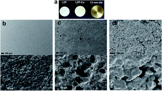 | ||
| Fig. 2 (a) LZP-1100 and LZP-Ca-1100 pellets obtained by sol–gel after sintering, compared to the die used to prepare the pellets before sintering. SEM images showing the microstructure of (b) as-prepared LZP-1100, (c) LZP-Ca-1100 and (d) LZP-1200,9 respectively. | ||
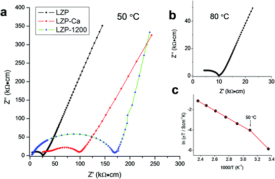
Impedance spectroscopy was used to characterize the Li+ transport properties of the LZP materials. Fig. 3a shows the typical impedance spectra of LZP-1100 and LZP-Ca-1100, compared with LZP-1200, at 50 °C.9 Although LZP-Ca-1100 and LZP-1200 possess a rhombohedral modification at room temperature, these phases showed higher total resistances compared with LZP-1100 due to significant contributions from grain boundary resistances. The total conductivity of LZP-1100 reaches 1.0 × 10⁻⁴ S cm−1 at 80 °C, which is significantly higher than the conductivities of previously reported LZP phases5–9 and close to the conductivity recently reported for spark plasma sintered phases (1.8 × 10⁻⁴ S cm−1 at 80 °C).12 Analysis of the impedance spectra of LZP-1100 is shown in Fig. S4.† The variable temperature impedance spectroscopy studies (Fig. 3c) reveal a Li+ transport activation energy of 0.34 eV in the temperature range of 50 °C to 150 °C. Unlike garnet-type solid-electrolytes,14 preliminary XPS studies indicate no accumulation of Li2CO3 on the pellet surface after exposure to air for several days, which indicates good stability of the material in air (Fig. S5†). These results suggest the suitability of the as-prepared LZP (LZP-1100) as a solid-electrolyte material for an all-solid-state battery.
In order to study the electrochemical compatibility of as-prepared LZP and Li metal anodes, a symmetric cell in which an LZP-1100 pellet is sandwiched between two Li electrodes (Li/LZP/Li) was studied. The impedance collected from a fresh symmetric cell at 50 °C (Fig. 4) showed a single semicircle representing the total resistance of the system12 and indicated a very high resistance. The observed high resistance, compared with the resistance obtained using Au electrodes, suggests that the interfacial resistance between LZP and Li is very high. To investigate the origin of this high interfacial resistance, thin layers of an Au buffer are used to improve the contact between the LZP-1100 and Li electrodes. This was motivated by previous observations which demonstrated that using thin layers of Au buffer greatly improved the contact between lithium anodes and solid electrolytes such as in the case of Ta-doped Li7La3Zr2O12.15 The observed impedance spectrum in our case (Fig. 4) consisted of a large semicircle corresponding to the total resistance of the cell and a small low-frequency semicircle likely corresponding to the interaction of the Li electrode with Au.15 The total resistance of the cell dramatically decreased upon application of the Au buffer, indicating that the high interfacial resistance is related to the inhomogeneous contact between the pellet and the Li electrode. We attribute this effect to the roughness of the surface of the pellets after polishing (Fig. 5a), and to the rough surface of the Li foil. The impedance spectra collected from different pellets at 80 °C are shown in the inset in Fig. 4. At 80 °C, and using an Au buffer, an area specific resistance (ASR) of ∼750 Ω cm2 can be estimated for the Li/LZP interface, where the approach employed in ref. 16–18 is used to calculate the ASR. This value is comparable to the ASR values observed for Al-substituted Li7La3Zr2O12 using pellets of similar thickness;14,16 however, studies on garnet-type solid electrolytes indicate that the ASR varies greatly depending upon the surface microstructure.14,16–18
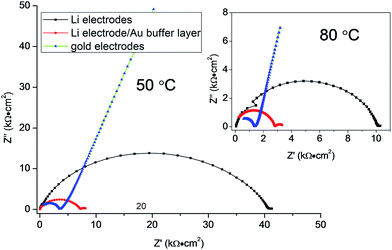 | ||
| Fig. 4 Impedance plots of LZP-1100 using different electrodes at 50 °C (pellet thickness = 1.5 mm). The inset shows the spectra collected at 80 °C. | ||
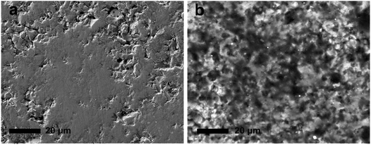 | ||
| Fig. 5 SEM images of the surface of LZP-1100 pellet before (a) and after (b) galvanostatic cycling at 80 °C for 100 h (40 μA cm−2). | ||
The interface between LZP and Li was further studied by time-dependent impedance and galvanostatic cycling. Time-dependent impedance studies showed a slow increase in resistance with time (Fig. S6†), which indicates instability of the solid-electrolyte in contact with lithium.19–21 This is consistent with recent density functional theory (DFT) studies on the electrochemical window of LZP.22 The stability of the Li/LZP interface upon lithium dissolution/deposition was tested by cycling fresh symmetric Li/LZP/Li cells at different current densities. At low current densities (40 μA cm−2; 80 °C), the Li/LZP interface is found to be relatively stable upon cycling up to 100 h, as evidenced by an insignificant increase of the cell voltage upon cycling (Fig. 6a). The starting voltage of the cell (∼0.4 V) suggests a direct-current (dc) resistance consistent with the alternating-current (ac) resistance observed by impedance spectroscopy. The starting voltage dramatically decreased to ∼0.18 V on using the Au buffer. However, the stability of the interface upon cycling is significantly reduced, as indicated by the increase voltage observed upon cycling (Fig. 6b). Cycling Li/LZP/Li cells at higher current densities (e.g. 100 μA cm−2) resulted in a significant increase in the voltage of the cell (Fig. S7†).
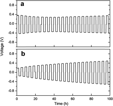 | ||
| Fig. 6 Galvanostatic cycling of (a) the Li/LZP/Li symmetric cell, (b) the Li/LZP/Li symmetric cell using Au buffer, at 80 °C and 40 μA cm−2 current density. | ||
We observed no instant colour change of LZP-1100 after contact with lithium metal at room temperature. However, when a symmetric Li/LZP/Li cell was cycled at 80 °C for 100 h, a black layer was formed on the surface of the pellet (Fig. S8†). No evidence of phase decomposition could be observed by XRD, indicating that this black layer coating the surface particles is most likely amorphous. SEM examination revealed this layer as a glassy phase covering the surface (Fig. 5b). Since, upon cycling, the symmetric Li/LZP/Li cell maintains constant resistance, in agreement with the initial resistance derived from impedance spectroscopy (Fig. 6a), the surface layer is assumed to be Li+ conductive and serves as a solid-electrolyte interphase between Li and LZP. The increase in resistance upon cycling observed in cells containing the Au buffer is most likely a result of an interfacial reaction involving Au upon Li+ cycling. This reaction appears to be accelerated by increasing temperature, since the increase of the cell resistance was less pronounced when the cell was cycled at a lower temperature of 50 °C (Fig. S7†).
Compared to spark plasma sintered LZP,12 we generally observe a more resistive Li/LZP interface upon cycling, which points to the importance of surface microstructure. Inhomogeneous, less compact surfaces possess higher interfacial resistances due to insufficient contact between Li and the solid electrolyte, making it more difficult to produce a dense SEI layer which effectively wets both the LZP and Li electrodes. The formation of a stable Li+ conductive passivation layer due to a reaction between the solid electrolyte and Li is observed, for example, in thiophosphate materials whose mechanical properties allow better physical contact with electrodes.19,23 The formation of a dense SEI that wets both the solid electrolyte and the Li electrode in robust ceramic systems is expected to be greatly dependent on the surface microstructure.
Li et al. suggested the formation of a solid electrolyte interface layer of Li3P and Li8ZrO6 on LZP upon Li+ cycling, based on the analysis of a similar black surface layer obtained by heating LZP with Li at 350 °C.12 To explore this in detail for our LZP-1100 material, we have examined the black surface layer produced by cycling a Li/LZP/Li cell at 80 °C for 100 h using XPS (Fig. 7). A clear enrichment of Li in the black surface layer region can be seen from the Li 1s core line spectra. Quantitative analysis of the increase in Li based on the Li 1s core line is not possible due to the overlap with the Zr 4s line and the small cross section. The Zr 3d core level (Fig. 7b) shows that in the black area a lower binding energy (BE) contribution at 181.6 eV increases dramatically compared to the main LZP peak at 184.0 eV. This feature is consistent with Zr–O environments like the one found in Li8ZrO6. In addition, there are two phosphorous environments observed in the P 2p core level at 134.2 eV for LZP and a lower BE contribution at 133.4 eV which is associated with the formation of Li3P. Finally, the O 1s core level also exhibits an increase of a lower BE component related to the formation of Li8ZrO6. These results point strongly towards the formation of a Li3P/Li8ZrO6 layer on the surface, further supporting the proposed decomposition of LZP reported by Li et al. Li3P displays an ionic conductivity of greater than 10−4 S cm−1 at ambient temperature, minimal electronic conductivity and good electrochemical stability,24 all of which support the case for the Li3P/Li8ZrO6 layer acting as an SEI.
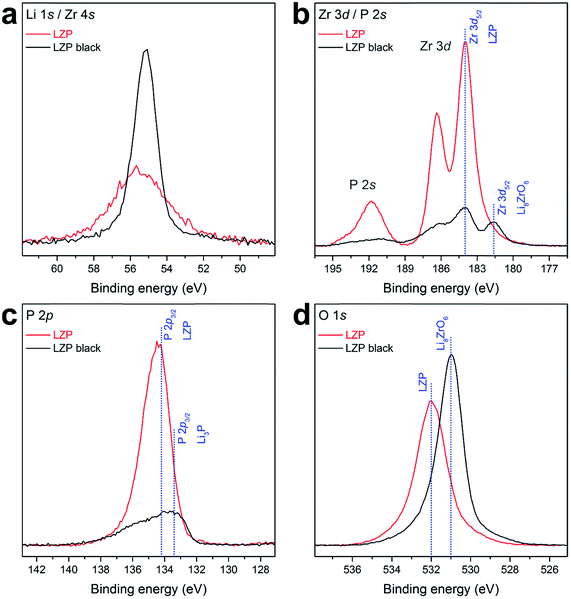 | ||
| Fig. 7 XPS core levels of LZP-1100 and the black surface layer (LZP black) formed after cycling a Li/LZP/Li cell at 80 °C for 100 h, including (a) Li 1s/Zr 4s, (b) Zr 3d/P 2s, (c) P 2p, and (d) O 1s. | ||
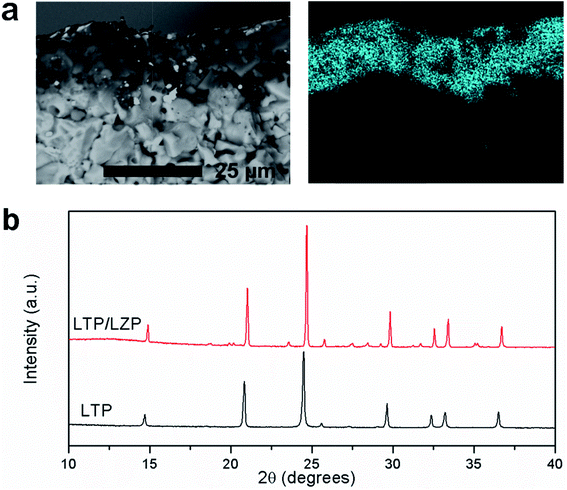
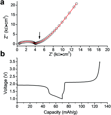
Finally, we have studied LiTi2(PO4)3 (LTP) as a potential electrode material for a proposed LZP-based all-solid-state battery. An approximately 10 μm thick LTP layer was successfully deposited on LZP. Fig. 8a shows a longitudinal section of the LZP pellet after depositing LTP and the Ti distribution in the sample as determined by EDX elemental mapping. The XRD pattern collected from the surface of the pellet (Fig. 8b) confirms that the LTP structure and crystallinity are retained, with no indication of phase decomposition or reaction with the substrate (i.e. LZP). In order to investigate the electrochemical compatibility of LTP and the LZP solid-electrolyte, we constructed an all-solid-state battery prototype in which a Li electrode is attached to the bare surface of the LZP pellet, while an Au layer deposited on LTP is used to collect current from the LTP electrode. A thin Au buffer layer was employed at the Li side in order to reduce the interfacial resistance. Fig. 9a shows the impedance spectrum collected from the battery at 50 °C. The spectrum consisted of a high-frequency distorted semicircle, an intermediate-frequency semicircle, and a low frequency Warburg impedance. This was successfully fitted using the equivalent circuit R[RQ][RQ][RQ]W, where the high frequency part of the spectrum required two RQ elements for a reasonable fit. To assign the modelled RQ elements, we measured the impedance from a similar cell which contained no LTP layer, i.e. a Li/LZP/Au cell, as a control experiment (Fig. S9†). The impedance in this case consisted of one distorted semicircle, fitted by two RQ elements, corresponding to the total resistance of the solid electrolyte and Li/solid-electrolyte interface (Fig. S9†). The disappearance of the intermediate-frequency semicircle clearly suggests that this contribution corresponds to the LTP layer in the solid-state cell. The refined capacitance of this semicircle is 1.6 × 10⁻⁷ F, which is highly consistent with a surface layer contribution to the impedance.25,26 This interfacial resistance is ∼1150 Ω cm2 under the applied conditions (50 °C; a pellet thickness of ∼0.9 mm). Fig. 9b and S10† show the discharge/charge profiles of the Li/LZP/LTP solid-state battery at 50 °C and 80 °C, yielding specific discharge capacities of 70 and 115 mA h g−1 respectively. However, the battery displayed poor cycle performance as indicated by a rapid capacity loss with repeated cycling (Fig. S10†). Interestingly, SEM images taken of the post-cycled materials showed no significant degradation of the LZP/LTP interface after cycling (Fig. S11†), suggesting good stability against volume changes associated with Li insertion/extraction in LTP. We therefore attribute the poor cycling performance observed to the poor electronic conductivity of the cathode layer. Conductive carbon additives, typically applied to improve electronic conductivity, could not be applied here due to incompatibility with the co-sintering synthetic procedure employed. However, these proof-of-concept results indicate excellent chemical compatibility between LTP and LZP up to 1100 °C, relatively low interfacial resistance and retention of the solid–solid interface upon cycling. Our results demonstrate the promising suitability of these materials for solid-state battery applications, e.g. in thin-film battery configurations. For bulk battery configurations, a suitable manipulation of the LTP architecture is required in order to allow good electronic contact with the current collector (e.g. preparation of porous surface structures that could be wetted by conductive additives).
Conclusions
We have prepared dense LZP phases by quenching sol–gel processed solid precursors from 1100 °C for the first time. Due to reduction of grain boundary resistances, the as-prepared phases (LZP-1100) possess higher total conductivity than previously reported LZP phases and conductivity values close to spark plasma sintered phases. We demonstrate that the use of thin layers of Au buffer improves the contact between LZP and Li metal and effectively reduces the interfacial resistance. Upon Li+ cycling, a surface layer of Li3P/Li8ZrO6 is formed on LZP. The interface is Li+ conductive and has a stable resistance upon Li+ cycling at relatively low current densities. It is proposed that the surface microstructure plays a critical role in determining the interfacial resistance and the stability of the interface upon cycling. Homogeneous, highly dense surfaces are required to achieve less resistive and more stable interphases upon Li+ cycling. This highlights the importance of engineering of the surface microstructure to obtain stable SEI with Li in case of robust ceramic solid-electrolytes. LTP shows excellent chemical and electrochemical compatibility with LZP and is suggested as a potential electrode material in proposed LZP-based all-solid-state batteries.Conflicts of interest
There are no conflicts to declare.Acknowledgements
This work was supported by funding from the EPSRC (EP/N001982/1) and we thank the School of Chemistry at the University of Glasgow for support. The authors gratefully acknowledge the help and technical support of Mr Michael Beglan and Mr Peter Chung. D. J. P. acknowledges the support of EPSRC (EP/M028291/1), and the Royal Society (UF100105 & UF150693).References
- H. Aono, E. Sugimoto, Y. Sadaoka, N. Imanaka and G.-Y. Adachi, J. Electrochem. Soc., 1990, 137, 1023 CrossRef CAS
.
- J. S. Thokchom and B. Kumar, J. Power Sources, 2010, 195(9), 2870 CrossRef CAS
.
- S. Hasegawa, N. Imanishi, T. Zhang, J. Xie, A. Hirano, Y. Takeda and O. Yamamoto, J. Power Sources, 2009, 189, 371 CrossRef CAS
.
- P. Hartmann, T. Leichtweiss, M. R. Busche, M. Schneider, M. Reich, J. Sann, P. Adelhelm and J. Janek, J. Phys. Chem. C, 2013, 117, 21064 CAS
.
- D. Petit, P. Colomban, G. Collin and J. P. Boilot, Mater. Res. Bull., 1986, 21, 365 CrossRef CAS
.
- M. Casciola, U. Costantino, L. Merlini, I. G. K. Andersen and E. K. Andersen, Solid State Ionics, 1988, 26, 229 CrossRef CAS
.
- F. Sudreau, D. Petit and J. P. Boilot, J. Solid State Chem., 1989, 83, 78 CrossRef CAS
.
- J. E. Iglesias and C. Pecharromán, Solid State Ionics, 1998, 112, 309 CrossRef CAS
.
- H. El-Shinawi, C. Greaves and J. Janek, RSC Adv., 2015, 5, 17054 RSC
.
- H. Xie, J. B. Goodenough and Y. Li, J. Power Sources, 2011, 196, 7760 CrossRef CAS
.
- Y. Li, M. Liu, K. Liu and C.-A. Wang, J. Power Sources, 2013, 240, 50 CrossRef CAS
.
- Y. T. Li, W. D. Zhou, X. Chen, X. J. Lu, Z. M. Cui, S. Xin, L. G. Xue, Q. X. Jia and J. B. Goodenough, Proc. Natl. Acad. Sci. U. S. A., 2016, 113, 13313 CrossRef CAS PubMed
.
- H. El-Shinawi and J. Janek, RSC Adv., 2015, 5, 14887 RSC
.
- L. Cheng, E. J. Crumlin, W. Chen, R. Qiao, H. Hou, S. Franz Lux, V. Zorba, R. Russo, R. Kostecki, Z. Liu, K. Persson, W. Yang, J. Cabana, T. Richardson, G. Chen and M. Doeff, Phys. Chem. Chem. Phys., 2014, 16, 18294 RSC
.
- C. L. Tsai, V. Roddatis, C. V. Chandran, Q. L. Ma, S. Uhlenbruck, M. Bram, P. Heitjans and O. Guillon, ACS Appl. Mater. Interfaces, 2016, 8(16), 10617 CAS
.
- L. Cheng, J. S. Park, H. Hou, V. Zorba, G. Chen, T. Richardson, J. Cabana, R. Russo and M. Doeff, J. Mater. Chem. A, 2014, 2, 172 CAS
.
- L. Cheng, W. Chen, M. Kunz, K. A. Persson, N. Tamura, G. Chen and M. Doeff, ACS Appl. Mater. Interfaces, 2015, 7, 2073 CAS
.
- L. Cheng, C. H. Wu, A. Jarry, W. Chen, Y. F. Ye, J. F. Zhu, R. Kostecki, K. Persson, J. H. Guo, M. Salmeron, G. Y. Chen and M. Doeff, ACS Appl. Mater. Interfaces, 2015, 7, 17649 CAS
.
- S. Wenzel, D. A. Weber, T. Leichtweiss, M. R. Busche, J. Sann and J. Janek, Solid State Ionics, 2016, 286, 24 CrossRef CAS
.
- S. Wenzel, S. Randau, T. Leichtweiß, D. A. Weber, J. Sann, W. G. Zeier and J. Janek, Chem. Mater., 2016, 28(7), 2400 CrossRef CAS
.
- P. Bron, B. Roling and S. Dehnen, J. Power Sources, 2017, 352, 127 CrossRef CAS
.
- Y. Noda, K. Nakano, H. Takeda, M. Kotobuki, L. Lu and M. Nakayama, Chem. Mater., 2017, 29, 8983 CrossRef CAS
.
- W. D. Richards, L. J. Miara, Y. Wang, J. C. Kim and G. Ceder, Chem. Mater., 2016, 28, 266 CrossRef CAS
.
- G. Nazri, Solid State Ionics, 1989, 34, 97 CrossRef CAS
.
- J. T. S. Irvine, D. C. Sinclair and A. R. West, Adv. Mater., 1990, 2, 132 CrossRef CAS
.
- W. B. Reid and A. R. West, Solid State Ionics, 1988, 28–30, 681 CrossRef
.
Footnote |
| † Electronic supplementary information (ESI) available. See DOI: 10.1039/c7ta08715b |
| This journal is © The Royal Society of Chemistry 2018 |

