DOI:
10.1039/C8SM00114F
(Paper)
Soft Matter, 2018,
14, 7671-7679
Controlled cavity collapse: scaling laws of drop formation†
Received
15th January 2018
, Accepted 29th July 2018
First published on 3rd September 2018
Abstract
The formation of transient cavities at liquid interfaces occurs in an immense variety of natural processes, among which the bursting of surface bubbles and the impact of a drop on a liquid pool are salient. The collapse of a surface liquid cavity is a well documented natural process that leads to the ejection of a thin and fast jet. Droplets generated through this process can be one order of magnitude smaller than the cavity's aperture, and they are consequently of interest in drop on demand inkjet applications. In this work, the controlled formation and collapse of a liquid cavity is analyzed, and the conditions for minimizing the resulting size and number of ejected drops are determined. The experimental and numerical models are simple and consist of a liquid reservoir, a nozzle plate with the discharge orifice, and a moving piston actuated by single half-sine-shaped pull-mode pulses. The size of the jetted droplet is described by a physical model resulting in a scaling law that is numerically and experimentally validated.
1 Introduction
The controllable generation of small droplets and aerosols is of great importance in a large variety of technologies, ranging from drug delivery to microfluidics, crop spraying and inkjet printing. In particular, inkjet has been a key driver in the recent interest in droplet generation techniques as it is directly relevant to a variety of modern digital non-contact manufacturing processes, such as graphic printing,1 fabrication of transistors,2 biochip arraying,3 bioprinting4 and 3D printing.5,6 Drop on Demand generators (DoD) are attracting interest due to their ability to controllably deliver minuscule volumes of materials onto a variety of surfaces in a digital non-contact process.7–10
DoD technologies based on piezoelectric elements were initially proposed by Zoltan11 in 1972, and they were later improved to the most common configuration by Kyser and Sears12 in 1976. The simplest design consists of a glass capillary bonded to a piezoelectric element, with a small nozzle at one of its ends.13 By carefully selecting a suitable voltage pulse, the capillary is squeezed and/or relaxed, and a droplet similar in size to that of the nozzle is ejected. The overarching challenge faced by the piezo-DoD method is finding the appropriate shape, amplitude and duration of the voltage pulse (the so-called ‘waveform’ in the inkjet jargon) that will actuate the piezo-element and ultimately produce one droplet per pulse. Great care is taken (with fine tuning carried out empirically by trial-and-error methods) to produce one single droplet without the generation of undesirable so-called satellite droplets.
The ability to control the droplet volume is of fundamental importance, especially if one wants to define or increase the printing resolution while also reducing fluid consumption. In particular, minimizing the droplet size in a controllable fashion has therefore become a major driver, and challenge, for the scientific community. One immediate solution is to reduce the nozzle size.14–19 However, this leads to many problems as smaller nozzles are prone to clogging and are difficult to manufacture, clean and maintain. Methods to reduce the droplet size without necessarily reducing the size of the nozzle have then become desirable. Chen and Basaran20,21 in 2001 developed a new technique to produce droplets that are 50% smaller than the nozzle radius by controlling and exploiting the capillary, viscous and inertial time scales in a piezo-driven squeeze-mode glass nozzle. This was achieved by replacing the traditional pull–push pulse by a pull–push–pull waveform to suppress the formation of a primary ‘large’ droplet while simultaneously inducing the detachment of a tongue of fluid which led to the formation of a tiny droplet, smaller than the diameter of the nozzle. A few years later, the same group devised another method,22 for the ejection of even smaller droplets from such nozzles. The method works by finding and exploiting resonances between capillary waves at the surface of the meniscus and an oscillatory inflow, driven by consecutive sinusoidal waveforms. The hydrodynamic interaction between these surface capillary waves and oscillatory inflows led to the generation of a short-lived high-pressure region in the centre of the capillary just under the surface of the interface/meniscus. If these pressures were high-enough to overcome surface tension, ultra-small droplets were ejected from the center of the meniscus. In a different work,23 a modulation of the size of the ejected droplets in a DoD printhead was achieved by stimulating multiple piezoelectric elements with different spectral distributions, each exciting a different resonance mode at the fluid interface. By tailoring waveforms in this way, they were capable of stimulating the fluid interface to oscillate with one single mode while at the same time quenching others. If the amplitude of the perturbation and hence the oscillation was large enough, a droplet, with a size comparable to that of the center excursion of the oscillating meniscus, was ejected. Since the size of such a zone for high-order oscillation modes was much smaller than the orifice, the generated inkjet droplets were significantly smaller than the nozzle.
On the other hand, researchers have reported the generation of thin and fast jets after the collapse of liquid surface cavities. This phenomenon is a common source of fine aerosols of mechanical origin from quasi-static liquid surfaces, and examples of these are bubbling24–27 and droplet or solid impact28 onto liquid pools. In most of these examples, a drop, or a series of drops, is generated as the result of the cavity collapse, raising the potential of using such a violent event to produce drops on demand. Based on the phenomenon of cavity collapse, Castrejón-Pita et al.29 devised an alternative design to produce diminutive droplets by carefully controlling the pressure inside a simple liquid-filled reservoir in order to induce the formation and sudden collapse of a small liquid cavity at the interface of an open orifice – the nozzle. Central to the performance of this system is the application of a negative pressure pulse that creates a cavity at the nozzle (inverted meniscus) followed by its subsequent rapid collapse, leading to the formation of a thin and fast jet, as shown in Fig. 1. Under the right conditions, a single, small and fast droplet breaks up from the jet's tip, with the rest of the ejected liquid recoiling back into the reservoir. A major advantage of this system is its clogging-proof nature, as it can handle heavily loaded liquids (e.g. pigment-based inks and colloids) while still being able to produce very small droplets. Also, depending on the actuation and timescales of the piston, this system produces a wider droplet-size spectrum compared to conventional methods. In this sense, this system is analogous to the flow focusing method30 for steady jet emission. In this work, we present scaling arguments to predict droplet generation from the collapse of liquid cavities. Compared to the problem of jet ejection from bubble bursting,25,36–39 the number of degrees of freedom and operating parameters makes this problem much more complex, but yet we show its main features are similar to the much simpler former natural process. In this regard, we show that the new degrees of freedom bring out their associated non-dimensional parameters without compromising the basic physical principles shared with bubble bursting, but adding new possibilities of fine-tuning for various practical applications. The approach is also practical as it aims to control the size of droplets making the system useful in inkjet applications.7,9
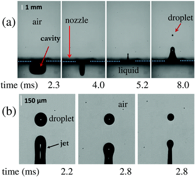 |
| | Fig. 1 (a) Single droplet ejection from a controlled cavity collapse using silicone oil (10 cSt) and a 2 mm (diameter) nozzle. (b) Zoom into the pinch-off region, showing the change in the size of the ejected droplet for three different piston speeds at approximately the same time. All the images were obtained using a shadowgraphy system, in which drastic changes in refractive indices result in high intensity contrasts. Therefore, both the cavity and droplet appear as dark regions. In this case, without losing the generality or applicability of the system, the system was arranged in such a way that the droplets were traveling upwards. | |
2 Experimental setup
The systematic parametric study carried out for this investigation included both experiments and numerical simulations. We used a setup based on29 jet liquid droplets from collapsing cavities. The schematic view of the experimental setup is shown in both Fig. 2 and 3.
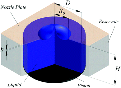 |
| | Fig. 2 Sketch of the droplet generator system highlighting the main dimensions (not in scale). | |
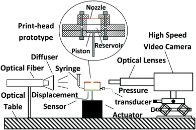 |
| | Fig. 3 Experimental setup comprising the droplet generator and the imaging system assembled on a vibration-reduction optical table. | |
In brief, the experiment comprises a reservoir with the internal shape of that of a circular cylinder, machined out of polymethyl methacrylate, with diameter D = 30.0 mm and height H = 20.0 mm. Similar to the original design in ref. 29, a thin brass sheet of thickness h = 0.25 mm with a circular nozzle with radius R0 = 1 mm in its center is fixed to the top of this reservoir, as shown in Fig. 2. The bottom end consists of a circular piston that moves by the action of an electro-mechanical actuator (YMC MS-20), which is in turn driven by a simple pull-mode (half-cycle) sine waveform. The input signal for the piston that produces the cavity is plotted in Fig. 4. The properties of the sine-shaped pulse, such as amplitude and width, are designed within a LabView code. The waveform is therefore generated by a National Instrument acquisition card (USB X Series) and amplified by an integrated amplifier (ROTEL RA-921). A fibre optic displacement sensor (D6-C1H1) and a pressure transducer (Honeywell 40PC001B) are utilized to measure the displacement of the piston and the pressure inside the reservoir, respectively. When the negative pulse is applied, and since the fluid is pinned to the circular nozzle, the meniscus is pulled back into the reservoir forming a liquid cavity. Then, the piston moves towards the nozzle, producing the positive pressure that drives the collapse of the cavity, subsequently ejecting a thin liquid jet. Finally, the tip of the jet breaks up, delivering a fast droplet with a size comparable to that of the jet. After breakup, the meniscus relaxes to its original position at the nozzle. For the experiments described in the following text, the input pulse width is set to tpw = 4.2 ms.
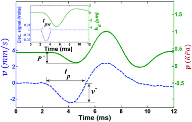 |
| | Fig. 4 Driving electrical waveform pulse and its corresponding piston displacement hd (top left figure), piston velocity v and the pressure inside the reservoir p (main figure). tpw and tp are the pulse widths in terms of the electrical signal and velocity, respectively. Our results show that the driving pulse width and the time for cavity collapse occur at the same order of magnitude, typically a few milliseconds. Dataset available in the ESI.†![[thin space (1/6-em)]](https://www.rsc.org/images/entities/char_2009.gif) 40 40 | |
Images were typically captured at 50![[thin space (1/6-em)]](https://www.rsc.org/images/entities/char_2009.gif) 000 frames per second by a high speed camera (Phantom V12.1) coupled to a macro lens (90 mm Tamron) or a microscope lens (12× Navitar lens). A cool-white light source (PhotoFluor II) coupled to a micro-structured optical diffuser (Thorlabs) provided uniform lighting to back-illuminate the system. The camera field of view was 5.1 × 8.0 mm2 in which the pixel size is equal to 0.24 μm. The cavity collapse, the jetting and the droplet position were recorded by high-speed imaging at all times during the jetting process. The diameter of the droplet was obtained by image analysis software (ImageJ) after calibration. The working fluid was introduced into the reservoir through a tube connected to a syringe opened to the atmosphere. The syringe is mounted on a micrometre stage to fill and level off the reservoir and to control the interface formed at the orifice (the meniscus).
000 frames per second by a high speed camera (Phantom V12.1) coupled to a macro lens (90 mm Tamron) or a microscope lens (12× Navitar lens). A cool-white light source (PhotoFluor II) coupled to a micro-structured optical diffuser (Thorlabs) provided uniform lighting to back-illuminate the system. The camera field of view was 5.1 × 8.0 mm2 in which the pixel size is equal to 0.24 μm. The cavity collapse, the jetting and the droplet position were recorded by high-speed imaging at all times during the jetting process. The diameter of the droplet was obtained by image analysis software (ImageJ) after calibration. The working fluid was introduced into the reservoir through a tube connected to a syringe opened to the atmosphere. The syringe is mounted on a micrometre stage to fill and level off the reservoir and to control the interface formed at the orifice (the meniscus).
3 Numerical simulations
Numerical simulations were based on mass continuity, momentum conservation, and liquid volume fraction equations for the incompressible flow regime and were resolved by the VoF scheme, implemented in the commercial solver FLUENT14.0. The axisymmetric configuration of the numerical simulations is illustrated in Fig. 5(a). A uniform velocity distribution at the inlet was assumed, which corresponded to the velocity of the piston v(t). Additionally, a uniform pressure distribution was prescribed over the outlet section, which was located H/2 away from the nozzle. The initial conditions for the pressure and velocity fields are considered to be zero in both the liquid and gas phases. Finally, nonslip boundary conditions were imposed at the solid walls. A mesh consisting of 286![[thin space (1/6-em)]](https://www.rsc.org/images/entities/char_2009.gif) 792 rectangular cells was used to spatially discretise the equations. In these simulations, two mesh sizes (5 and 500 μm per mesh length unit) were used to speed up the computational time, i.e. a finer mesh was used in the area covered by the movement of the meniscus/cavity. In our experiments and simulations, our droplet diameter ranged between 58 and 800 μm. Hence, the mesh size is about 12 times smaller than the smallest droplet, which is enough to avoid numerical diffusion at the droplet interface. Fig. 5(b) shows the mesh distribution; in green, the fine mesh and in light-blue, the coarse mesh. Our stability analysis shows that our results are not affected by this mesh selection. The interface between the two phases was tracked by solving the continuity equation for the volume fraction of the liquid phase. This calculation was performed by using an explicit time-marching scheme, while the rest of the equations were solved implicitly. The time step Δt was around 0.5 μs to ensure that the global Courant number Co = vmΔt/Δy (where vm is the mean velocity in the cell and Δy is the cell size) was less than unity.
792 rectangular cells was used to spatially discretise the equations. In these simulations, two mesh sizes (5 and 500 μm per mesh length unit) were used to speed up the computational time, i.e. a finer mesh was used in the area covered by the movement of the meniscus/cavity. In our experiments and simulations, our droplet diameter ranged between 58 and 800 μm. Hence, the mesh size is about 12 times smaller than the smallest droplet, which is enough to avoid numerical diffusion at the droplet interface. Fig. 5(b) shows the mesh distribution; in green, the fine mesh and in light-blue, the coarse mesh. Our stability analysis shows that our results are not affected by this mesh selection. The interface between the two phases was tracked by solving the continuity equation for the volume fraction of the liquid phase. This calculation was performed by using an explicit time-marching scheme, while the rest of the equations were solved implicitly. The time step Δt was around 0.5 μs to ensure that the global Courant number Co = vmΔt/Δy (where vm is the mean velocity in the cell and Δy is the cell size) was less than unity.
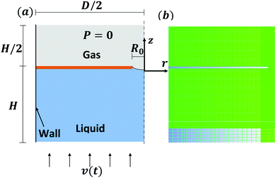 |
| | Fig. 5 (a) Simulation domain and (b) numerical mesh; in green, the fine mesh and in light-blue, the coarse mesh. | |
For the spatial discretisation of the equations, the third-order modified MUSCL scheme41 was used to obtain the face fluxes whenever a cell was completely immersed in a single phase. When the cell was near the interface, the GEO-RECONSTRUCTION algorithm was applied. The pressure corrections were computed with the bodyforce-weighted scheme, and the pressure-velocity coupling was treated with the PISO method42 in a segregated solver. All the simulations were conducted with D = 30 mm and H = 20 mm.
Further considerations
In order to compare numerical and experimental results, a number of practical considerations were required. First, the reservoir in the numerical model contains only one aperture, i.e. the nozzle. In contrast, the experimental setup has an additional liquid inlet used to adjust the position of the meniscus. Secondly, in the numerics, the nozzle plate was modelled as a solid rigid body but the thin brass plate on the prototype could suffer small deformations under the applied pressure. Consequently, during the pull phase in the experiment, the cavity volume (Vcavity) is equal to the displaced liquid volume by the action of the piston (Vpiston) minus the volume displaced inside the syringe and the volume displaced by the plate deformation (see the difference in Fig. 6). In order to take these effects into account, the velocity of the piston was adjusted to produce the same cavity volume as in the experiment at the peak backward piston displacement. Vcavity was measured by extracting the volume of the cavity using image analysis. Vpiston was in turn calculated by multiplying the displacement of the piston by the area of the reservoir. Within the studied experimental range, a cavity to piston displacement volume ratio of Vcavity/Vpiston ≃ 0.67 was determined. Simulations neither include the plate deformation nor the feeding system. Consequently, the piston velocity amplitude v−, in terms of the piston displacement hp, is calculated to give the same cavity volume as in the experiment:| |  | (1) |
| |  | (2) |
where A is the reservoir cross sectional area.
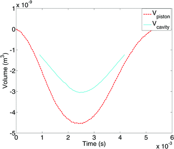 |
| | Fig. 6 Comparison between (Vpiston) and (Vcavity). | |
Influence of initial shape of the meniscus
Experiments revealed that the initial shape of the unperturbed meniscus also played a role during the jetting process and therefore had an effect on the droplet size in a more pronounced way than in bubble bursting.38 This was confirmed by numerical simulations, as shown in Fig. 7, where the evolution of the liquid interface is plotted for both a flat and a concave initial meniscus. Simulations demonstrated that a concave meniscus with an initial maximum vertical distance of l0 = 0.5 mm (i.e., l0/R0 = 0.5, see Fig. 7(b)) increased the droplet size by 70% compared to the droplet produced by an initially flat meniscus. To further reduce the parametrical complexity of this study, the meniscus profile in the simulations will mimic those observed in the experiments.
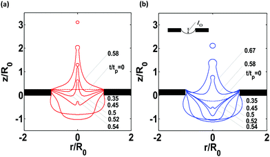 |
| | Fig. 7 Jetting simulation of silicone oil 10 cSt from the 2 mm diameter nozzle with a fixed piston velocity amplitude of 1.97 mm s−1 to show the influence of the initial meniscus form. (a) Plane meniscus and (b) concave meniscus. | |
The break up dynamics is complex and the correctness of numerical simulations is usually tested against well-known scaling laws of pinch off.43–47Fig. 8 shows, from simulations, the diameter of the minimum jet's neck as a function of time for a 5 cSt jetting event. This shows the inviscid45 regime and some indication of a transition towards the universal Inertial-Viscous regime.43,46 The axes have been made dimensionless using the nozzle radius R0 = 2 mm and capillary time  .
.
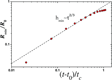 |
| | Fig. 8 Dimensionless neck radius as a function of dimensionless time to breakup for the case producing a droplet of d = 800 μm. | |
4 Experimental and numerical results
Our studies were focused on determining which characteristics of the system and liquid properties were relevant to the jetting and droplet breakup. Experiments were carried out using silicone oils with viscosities of 5 and 10 cSt as the working fluids; these are well-characterised Newtonian liquids with negligible dependance on the ambient temperature or humidity. The physical properties of these liquids are listed in Table 1. The largest liquid cavity formed in our experiments was 6 mm3 and we found that the cavity size is directly proportional to the piston velocity. Fig. 1(a) shows the jetting process using silicone oil (10 cSt).
Table 1 Physical properties of the liquids used in the experiments
| Liquid |
ρ (kg m−3) |
μ (cSt) |
γ (mN m−1) |
| Silicone oil (5 cSt) |
912 |
5 |
21.9 |
| Silicone oil (10 cSt) |
936 |
10 |
23.1 |
Experimental results show that the size of the droplet is determined by a plethora of parameters, including the piston velocity amplitude v− and the pulse width tp, as seen in Fig. 1(b). Increasing the piston velocity causes a larger kinetic energy transfer to the fluid around the nozzle. As a consequence, a thinner jet and a smaller droplet are produced. In fact, the jet speed increases with a faster collapse (shorter pulse). The kinetic energy introduced not only affects the droplet size and its speed, but it also determines the liquid ejection mode (single or multiple droplets). In particular, our interest is focused on the situation where a single droplet is ejected, as this is what most applications require, such as in inkjet. In addition to v− and tp, other important parameters are the liquid properties (viscosity μ, density ρ and surface tension σ), and the nozzle geometry (orifice radius R0 and thickness h).
The cases explored in the simulations are shown in Table 2. Fig. 9 shows the numerical simulation of the jetting process of silicone oil (10 cSt) at a velocity amplitude v− of 2 mm s−1 and pulse width of 4 ms. These numerical results along with the experiments provided sufficient evidence to allow us to propose a universal scaling argument, which is used to ultimately describe the dynamics across the explored parametric space.
Table 2 Cases considered in the numerical simulation
| Case |
R
0 (mm) |
h (mm) |
l
0 (mm) |
t
p (ms) |
ρ (kg m−3) |
μ (cSt) |
γ (mN m−1) |
| A |
0.5 |
0.25 |
0.38 |
4.2 |
936 |
10.0 |
23.1 |
| B |
0.75 |
0.25 |
0.38 |
4.2 |
936 |
10.0 |
23.1 |
| C |
1.0 |
0.5 |
0.38 |
4.2 |
936 |
10.0 |
23.1 |
| D |
1.0 |
0.75 |
0.38 |
4.2 |
936 |
10.0 |
23.1 |
| E |
1.0 |
0.25 |
0.38 |
3.0–4.2 |
936 |
1.0 |
23.1 |
| F |
1.0 |
0.25 |
0.38 |
4.2–5.0 |
936 |
2.0 |
23.1 |
| G |
1.0 |
0.25 |
0.38 |
4.2 |
912 |
5.0 |
21.9 |
| H |
1.0 |
0.25 |
0.38 |
4.2 |
936 |
6.0 |
23.1 |
| I |
1.0 |
0.25 |
0.38 |
4.2 |
936 |
7.5 |
23.1 |
| J |
1.0 |
0.25 |
0.38 |
4.2–6.0 |
936 |
10.0 |
23.1 |
| K |
1.0 |
0.25 |
0.38 |
4.2–5.0 |
936 |
10.0 |
60.0 |
| L |
1.0 |
0.25 |
0.38 |
4.2 |
1300 |
10.0 |
23.1 |
| M |
1.0 |
0.25 |
0.38 |
4.2 |
1800 |
10.0 |
23.1 |
| N |
1.0 |
0.25 |
0–0.5 |
4.2 |
936 |
10.0 |
23.1 |
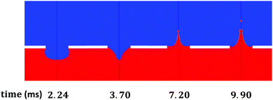 |
| | Fig. 9 Simulation of jetting out of cavity collapse from nozzle of 1 mm radius. | |
In the range explored in this work (please see Table 2), we found that diminutive droplets are produced for low surface tensions: a single droplet of silicon oil (5 cSt) with a radius of 27 μm can be produced when the surface tension equals σ = 21.9 mN m−1. The droplet sizes obtained from experiments and simulations, and their comparison are presented in Fig. 10. These results show that under the conditions used in this work, numerical simulations are able to appropriately capture the experimental findings.
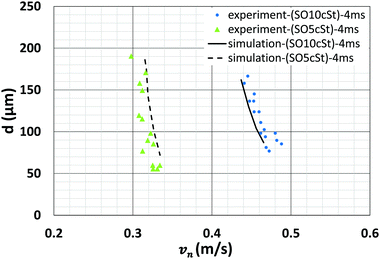 |
| | Fig. 10 Comparison between the droplet size in the numerical simulation and the experiments. | |
5 Scaling arguments
Studies on bubble bursting24–26,36,37 have identified a singularity involving the axial collapse of a wave front caused by the burst of a bubble film. The Ohnesorge number Oh = μ/(ρσR0)1/2 governs the phenomenon, where R0 is the equivalent radius of the parent bubble in these studies. That collapse is physically similar to the one observed in the controlled cavity collapse here reported. The origin of the singularity can be found in the competition between the capillary speed and the viscous damping as the wave front advances in the meridional direction when we increase piston velocity. When the wave reaches the axis, the radially collapsing momentum shoots the liquid ligament and ejects a droplet (i.e., creating a net surface). In that instant, the local competition among the surface tension forces, inertia and viscous forces at the point of surface curvature reversal38 leads to a scaling law where viscosity plays a counterintuitive role, producing a decrease in the size of the ejected ligament. This fact has been loosely interpreted as a focusing effect of viscosity37 that produces very small droplets from bubble bursting. This can be understood in terms of the amount of initially available mechanical energy that viscosity dissipates just before the wave collapses at the axis: within a certain parametrical window, viscosity reduces the momentum of that wave, which consequently yields a smaller size scale of the ejection, but not necessarily a smaller scale of the velocity of ejection.38 Therefore, there should be a limiting value of the viscosity above which no sufficient momentum is available at collapse to produce the ejection of a droplet. The existence of a critical Ohnesorge number Oh* ≃ 0.04,36 above which no droplets are ejected, supported this view. Experiment and simulations indicate that there is a minimum jet velocity in which a droplet breaks up and separates from the jet. Below this value, the kinetic energy is not high enough to overcome the surface tension – the energy is enough to form a jet but it is then pulled back into the reservoir without breaking up. Any excess of kinetic energy above this limit forms a droplet. In summary, an excess of energy drives the jet velocity in all cases of cavity collapse, and it controls the subsequent droplet ejection. In fact, in other phenomena, this energy surplus may come from several sources, e.g. the film's surface energy in bubble bursting,24 the surface electrical charge in the onset of electrospray,31–35 or the kinetic energy in drops impacting a liquid pool.28 In our system, this energy is introduced by the piston.
The analysis of the flow singularity at the collapse point can be made in terms of the local scales (geometrical and velocity scales) arising when the curvature of the surface at the axis undergoes a sudden change (the instants of curvature reversal). First, the amplitude and velocity of the wave that reaches the axis set a characteristic length L normal to the surface (i.e. in the axial direction) and a velocity scale V′ in the radial direction, respectively (see Fig. 11). Second, the size of the initiated jet front and its shooting speed set the droplet size d (i.e. the characteristic radial scale of the emission) and the scale of the axial velocity Vj, respectively. Using these four scales and the conservation equations of mass and momentum, Gañán-Calvo38 obtained the scaling relations of d, L, and V′ as functions of Vj that hold for this problem as well. The balance of all components of the momentum equation ρ(vt + v·∇v) + σ∇(∇s·n) − μ∇2v ≃ 0 in the radial direction, assuming O(vt) ∼ O(v·∇v), leads to:
| |  | (3) |
A third condition comes from mass continuity:
| | | V′Ld ∼ Vjd2 ⇒ Vj/V′ ∼ L/d. | (4) |
These three conditions lead to:
where
lμ =
μ2/(
ρσ) and
Vμ =
σ/
μ are the capillary-viscous length and velocity, respectively.
38 This scaling highlights the dependence of the ejected droplet size on the initial (or maximum) jet speed
Vj. The results of this universal scaling are shown for both bubble bursting and the present system in
Fig. 12, which shows that
d/
lμ =
Ad(
Vj/
Vμ)
−5/3, with
Ad ≃ 150.
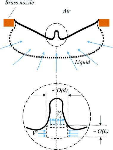 |
| | Fig. 11 Sketch of local spatial and velocity scales at the onset of jet ejection (surface curvature reversal at the axis). | |
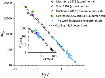 |
| | Fig. 12 Plots of the ejected droplet diameter dimensional vs. the maximum ejection speed for both numerical and physical experiments of bubble bursting and in the present system. Main plot: non dimensional values. Inset: Dimensional values (d in μm, Vj in m s−1). | |
In practical applications, the scaling in eqn (5) does not provide the general scaling of d as a function of the operation parameters as Vj is unknown. While simple energy considerations permit the calculation of this scaling for Vj in bubble bursting,38 the argument for cavity collapse and its additional degrees of freedom demands further considerations.
According to our experiments and simulations, the dynamics of droplet jetting from cavity collapse is determined by a set of nine dimensional parameters {ρ, σ, μ, R0, tp, vn, h, l0, g}, where l0 is the initial meniscus deformation from a flat surface (seen in Fig. 7), g is the acceleration of gravity, and  . According to the Buckingham-Pi method, these can be reduced to 6 non-dimensional parameters as: {Oh, tp/tc, vn/vc, l0/R0, h/R0, Bo}, where tc = (ρR03/σ)1/2 and vc = (σ/(ρR0))1/2 are the capillary time and velocity. Gravity effects36 are considered negligible in our experiments, i.e. Bo = ρgR02/σ ≪ 1, which effectively reduces the number of dimensionless parameters to five.
As previously discussed, a critical velocity vcritical defines the energy required to form a jet, but that is just short of producing a droplet. Under this notation, the effective mechanical energy excess ε ≃ Δ(ρvn2/2) ≃ ρvnΔv should be proportional to Δv = vn − vcritical assuming that Δv ≪ vn. In fact, we found that Δv/vn is below 0.20 for all the conditions producing droplets in our experiments. Consequently, Δv is used here as a convenient parameter that reflects the energy excess that should be fundamentally determined by the capillary velocity vc = (σ/(ρR0))1/2. Thus, the dependency of vcritical on the set of seven parameters {ρ, σ, μ, R0, tpw, l0, h} can be reduced to vcritical/vc = f(Oh,τ,λ1,λ2), where τ = tpw/tc, λ1 = l0/R0, and λ2 = h/R0.
Following the rationale found in a previous work,38 the conditions under which vcritical is met should correspond to that in which the total energy critically balances the kinetic energy of the ejected liquid column and the viscous dissipation. Thus, we introduce a critical Oh* controlling the droplet generation above which no droplet ejection occurs. Given the number of operational parameters of our system, Oh* cannot show the simple form exhibited in the bubble bursting problem. Following a systematic exploration of functional dependencies, and inspired by the work on bubble bursting36,38 where a critical Ohnesorge number was also used, we propose the following relationship:
| |  | (8) |
where

is defined for simplification. Here,
![[R with combining circumflex]](https://www.rsc.org/images/entities/i_char_0052_0302.gif)
is the characteristic length of the system that should depend on the rest of the parameters, {
τ,
λ1,
λ2}. A mathematical exploration of the simplest (polynomial) functional dependencies results in the following definitions:
| | ![[R with combining circumflex]](https://www.rsc.org/images/entities/i_char_0052_0302.gif) 0 = R0(λ1 + 5λ2 + 2λ22)2(τ2 + 0.05τ + 0.06)−2, 0 = R0(λ1 + 5λ2 + 2λ22)2(τ2 + 0.05τ + 0.06)−2, | (9) |
and
| | | f(Oh,τ,λ1,λ2) = exp[(4.20τ + 1.47 − 44.10/τ)Oh + λ1 − 2λ2 − λ22]. | (10) |
The numerical coefficients of eqn (9) and (10) were obtained using the experimental and simulation data, and they yield a Pearson regression coefficient of R2 > 0.93 for α = −0.093 and a critical value of  . This value is consistent with Oh* ≃ 0.040 obtained for bubble bursting36,38 (assuming
 ![[R with combining circumflex]](https://www.rsc.org/images/entities/i_char_0052_0302.gif) 0 as the equivalent parent bubble radius).
0 as the equivalent parent bubble radius).
Finally, an analysis of the dominant parametrical dependence of Vj on the rest of the parameters indicates that Vjtp/R0 ≈ 1. Again, among the infinite possible functional relationships, we propose an exponential form as:
| |  | (11) |
where
φ =
ϕβΨ1 +
Ψ2,
β,
A0 and
k are fitting parameters, with
ϕ = Δ
vρR02/(
tpσ) representing the last non-dimensional parameter to produce a rational expression for the role of the energy excess, and
| | | Ψ1,2 = Ψ1,2(Oh,τ,λ1,λ2). | (12) |
Our guide here is getting the maximum data collapse using the simplest possible functional dependencies. Linear programming optimisation yields
β = 0.33 ± 0.01,
A0 = 20.2, and
k = 0.8, with
| | | Ψ1 = 1 + 0.8Oh + 5Oh2 − 350Oh3 + 0.12τ + 0.055/τ + 0.25λ1 + 0.07λ12 + 0.7λ2 − 0.15λ22 | (13) |
and
| | | Ψ2 = −0.2Oh − 3Oh2 + 0.025/τ − 0.06λ1 + 0.09λ12 − 2.4λ2. | (14) |
In summary, we have six fitting parameters {Oh*,
Ad,
A0,
α,
β,
k} and four polynomic adjustable functional forms
(9), (10), (13) and (14).
Experiments and simulations were performed in the range of 3 < Re < 60 and the predicted speed. These are shown in Fig. 13. As discussed, droplet speed and droplet size are connected through the scaling argument presented in eqn (5); i.e., a potential law with a −5/3 exponent. By applying this scaling to eqn (11), one can obtain the droplet size shown in Fig. 14. These jetting parameters cover the known range in which single pinch-off droplets are known to exist.48
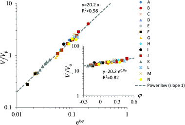 |
| | Fig. 13 Jet velocity Vj made dimensionless with either V0 = R0/tp (inset) or Vμ, showing the agreement of the scaling proposed. The open symbols represent experimental data while the closed symbols represent numerical data. | |
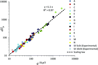 |
| | Fig. 14 Dimensionless droplet size  as a function of the scaling variable exp(−5kφ/3). as a function of the scaling variable exp(−5kφ/3). | |
6 Conclusions
In this work, we have presented experimental and numerical results aimed at gaining a better understanding of a novel method to produce droplets significantly smaller than the nozzles from which they emerge. Moreover, we have proposed a physical model and scaling law to predict the size of the generated droplet based on the liquid properties, the nozzle geometry, and the driving waveform. The resulting system can operate on a drop-on-demand mode, where the droplet generation is controlled by the piston velocity and the pulse width. This approach would also greatly benefit, for instance, grey-scale printing applications.
Conflicts of interest
There are no conflicts to declare.
Acknowledgements
This work was supported by the Royal Society (UF120319, URF\R\180016, and RGF\EA\180061), the John Fell Oxford University Press Research Fund (0005176), the EPSRC – UK (EP/P024173/1), and the Ministerio de Economía y Competitividad, Plan Estatal 2013–2016 Retos, project DPI2013-46485-C3-1-R.
References
- M. Doring, Ink-jet Printing, Philips Tech. Rev., 1982, 40, 192–198 Search PubMed.
- B. A. Ridley, B. Nivi and J. M. Jacobson, All-Inorganic Field Effect Transistors Fabricated by Printing, Science, 1999, 286, 746–749 CrossRef PubMed.
- M. Schena, R. A. Heller, T. P. Theriault, K. Konrad, E. Lachenmeier and R. W. Davis, Microarrays: biotechnology's discovery platform for functional genomics, Trends Biotechnol., 1998, 16, 301–306 CrossRef PubMed.
- A. D. Graham, S. N. Olof, M. J. Burke, J. P. K. Armstrong, E. A. Mikhailova, J. G. Nicholson, S. J. Box, F. G. Szele, A. W. Perriman and H. Bayley, High-Resolution Patterned Cellular Constructs by Droplet-Based 3D Printing, Sci. Rep., 2017, 7, 7004 CrossRef PubMed.
- Y. Guo, H. S. Patanwala, B. Bognet and A. W. K. Ma, Inkjet and inkjet-based 3D printing: connecting fluid properties and printing performance, Rapid Prototyping Journal, 2002, 33, 562–576 Search PubMed.
- L. E. Murr and W. L. Johnson, 3D metal droplet printing development and advanced materials additive manufacturing, J. Mater. Res. Technol., 2017, 6, 77–89 CrossRef.
- O. A. Basaran, Small-Scale Free Surface Flows with Breakup: Drop Formation and Emerging Applications, AIChE J., 2002, 48, 1842–1848 CrossRef.
- O. A. Basaran, H. Gao and P. P. Bhat, Nonstandard Inkjets, Annu. Rev. Fluid Mech., 2013, 45, 85–113 CrossRef.
- J. R. Castrejón-Pita, W. R. S. Baxter, J. Morgan, S. Temple, G. D. Martin and I. M. Hutchings, Future, Opportunities and Challenges of Inkjet Technologies, Atomization Sprays, 2013, 23, 541 Search PubMed.
-
Fundamentals of Inkjet Printing: The Science of Inkjet and Droplets, ed. Hoath, S. D., Wiley-VCH Verlag GmbH & Co., Weinheim, Germany, 2016 Search PubMed.
-
S. I. Zoltan, Pulsed droplet ejecting system, US Pat., 3683212, 1972 Search PubMed.
-
E. L. Kyser and S. B. Sears, Method and Apparatus for Recording with Writing Fluids and Drop Projection Means Therefor, US Pat., 3946398, 1976 Search PubMed.
- J. M. Montanero, A. M. Gañán-Calvo, A. J. Acero and E. J. Vega, Micrometer glass nozzles for flow focusing, J. Micromech. Microeng., 2010, 20, 075035 CrossRef.
- J. Kimura, Y. Kawana and T. Kuriyama, An Immobilized Enzyme Membrane Fabrication Method Using an Ink Jet Nozzle, Biosensors, 1988, 4, 41–52 CrossRef.
- W. J. Lloyd and H. H. Taub, Ink jet printing, Output Hardcopy Devices, 1988, 13, 311–370 Search PubMed.
- G. L. Bernardini, B. A. Rampy, G. A. Howell, D. J. Hayes and C. J. Frederickson, Applications of piezoelectric fluid jetting devices to neuroscience research, J. Neurosci. Methods, 1991, 38, 81–88 CrossRef PubMed.
-
T. M. Brennan, Method and apparatus for conducting an array of chemical reactions on a support surface, US Pat., 5474796, 1995 Search PubMed.
- H. P. Le, Progress and Trends in Ink-jet Printing Technology, J. Imaging Sci. Technol., 1998, 42, 49–62 Search PubMed.
- G. Perçin, A. Atalar, F. L. Degertekin and B. T. Khuri-Yakub, Micromachined two-dimensional array piezoelectrically actuated transducers, Appl. Phys., 1998, 72, 1397 Search PubMed.
- A. U. Chen and O. A. Basaran, A new method for significantly reducing drop radius without reducing nozzle radius in drop-on-demand drop production, Phys. Fluids, 2002, 14, L1–L4 CrossRef.
-
A. U. Chen and O. Basaran, Method and apparatus for producing drops using a drop-on-demand dispenser, US Pat., 6513894, 2003 Search PubMed.
-
X. Xu and O. A. Basaran, Method for producing ultra-small drops, US Pat., 8186790, 2012 Search PubMed.
-
R. F. Burr, D. A. Tence, H. P. Le, R. L. Adams and J. C. Mutton, Method for
producing ultra-small drops, US Pat. 5495270, 1996 Search PubMed.
- F. MacIntyre, Flow Patterns in Breaking bubbles, J. Geophys. Res., 1972, 77, 5211–5228 CrossRef.
- L. Duchemin, S. Popinet, C. Josserand and S. Zaleski, Jet formation in bubbles bursting at a free surface, Phys. Fluids, 2002, 14, 3000–3008 CrossRef.
- D. E. Spiel, On the births of jet drops from bubbles bursting on water surfaces, J. Geophys. Res., 1995, 100, 4995–5006 CrossRef.
- E. Ghabache, G. Liger-Belair, A. Antkowiak and T. Séon, Evaporation of droplets in a Champagne wine aerosol, Sci. Rep., 2016, 6, 25–48 CrossRef PubMed.
- A. L. Yarin, Drop impact dynamics: Splashing, spreading, receding, bouncing, Annu. Rev. Fluid Mech., 2006, 38, 159–192 CrossRef.
- A. A. Castrejón-Pita, J. R. Castrejón-Pita and G. D. Martin, A novel method to produce small droplets from large nozzles, Rev. Sci. Instrum., 2012, 83, 115105 CrossRef PubMed.
- A. M. Gañán-Calvo, Generation of Steady Liquid Microthreads and Micron-Sized Monodisperse Sprays in Gas Streams, Phys. Rev. Lett., 1998, 80, 285 CrossRef.
- R. T. Collins, M. T. Harris and O. A. Basaran, Breakup of electrified jets, J. Fluid Mech., 2007, 588, 75–129 Search PubMed.
- F. J. Higuera, Flow rate and electric current emitted by a Taylor cone, J. Fluid Mech., 2003, 484, 303–327 CrossRef.
- R. T. Collins, K. Sambath, M. T. Harris and O. A. Basaran, Universal scaling laws for the disintegration of electrified drops, Proc. Natl. Acad. Sci. U. S. A., 2013, 110, 4905–4910 CrossRef PubMed.
- F. J. Higuera, S. E. Ibáñez, A. J. Hijano and I. G. Loscertales, Pulsating emission of droplets from an electrified meniscus, J. Aerosol Sci., 2013, 66, 193–208 CrossRef.
- A. M. Gañán-Calvo, J. M. López-Herrera, N. Rebollo-Muñoz and J. M. Montanero, The onset of electrospray: the universal scaling laws of the first ejection, Sci. Rep., 2016, 6, 32357–32359 CrossRef PubMed.
- P. L. L. Walls, L. Henaux and J. C. Bird, Jet drops from bursting bubbles: How gravity and viscosity couple to inhibit droplet production, Phys. Rev. E: Stat., Nonlinear, Soft Matter Phys., 2015, 92, 021002(R) CrossRef PubMed.
- E. Ghabache and T. Séon, Size of the top jet drop produced by bubble bursting, Phys. Rev. Fluids, 2016, 1, 051901(R) CrossRef.
- A. M. Gañán-Calvo, Revision of Bubble Bursting: Universal Scaling Laws of Top Jet Drop Size and Speed, Phys. Rev. Lett., 2017, 119, 204502 CrossRef PubMed.
- L. Deike, E. Ghabache, G. Liger-Belair, A. K. Das, S. Zaleski, S. Popinet and T. Séon, Dynamics of jet produced by bursting bubbles, Phys. Rev. Fluids, 2018, 3, 013603 CrossRef.
- Dataset for the graphs in Fig. S3 are available as ESI†.
- R. I. Issa, Solution of the implicitly discretised fluid flow equations by operator-splitting, J. Comput. Phys., 1986, 62, 40–65 CrossRef.
- B. V. Leer, Towards the ultimate conservative difference scheme. V - A second-order sequel to Godunov's method, J. Comput. Phys., 1979, 32, 101–136 CrossRef.
- J. Eggers, Universal Pinching of 3D Axisymmetric Free-Surface Flow, Phys. Rev. Lett., 1993, 71, 3458 CrossRef PubMed.
- J. Eggers, Theory of drop formation, Phys. Fluids, 1995, 7, 941 CrossRef.
- R. F. Day, E. J. Hinch and J. R. Lister, Self-similar capillary pinchoff of an inviscid fluid, Phys. Rev. Lett., 1998, 80, 704 CrossRef.
- A. U. Chen, P. K. Notz and O. A. Basaran, Computational and experimental analysis of pinch-off and scaling, Phys. Rev. Lett., 2002, 88, 174501 CrossRef PubMed.
- J. R. Castrejón-Pita, A. A. Castrejón-Pita, S. S. Thete, K. Sambath, I. M. Hutchings, J. Hinch, J. R. Lister and O. A. Basaran, Plethora
of transitions during breakup of liquid filaments, Proc. Natl. Acad. Sci. U. S. A., 2015, 112, 4582–4587 CrossRef PubMed.
- B. Derby, Inkjet Printing of Functional and Structural Materials: Fluid Property Requirements, Feature Stability, and Resolution, Annu. Rev. Mater. Res., 2010, 40, 395–414 CrossRef.
Footnote |
| † Electronic supplementary information (ESI) available. See DOI: 10.1039/c8sm00114f |
|
| This journal is © The Royal Society of Chemistry 2018 |
Click here to see how this site uses Cookies. View our privacy policy here.  Open Access Article
 a,
Alfonso M.
Gañán-Calvo
b,
J. Rafael
Castrejón-Pita
 c,
Miguel A.
Herrada
b and
Alfonso A.
Castrejón-Pita
 *a
*a


![[thin space (1/6-em)]](https://www.rsc.org/images/entities/char_2009.gif) 40
40![[thin space (1/6-em)]](https://www.rsc.org/images/entities/char_2009.gif) 000 frames per second by a high speed camera (Phantom V12.1) coupled to a macro lens (90 mm Tamron) or a microscope lens (12× Navitar lens). A cool-white light source (PhotoFluor II) coupled to a micro-structured optical diffuser (Thorlabs) provided uniform lighting to back-illuminate the system. The camera field of view was 5.1 × 8.0 mm2 in which the pixel size is equal to 0.24 μm. The cavity collapse, the jetting and the droplet position were recorded by high-speed imaging at all times during the jetting process. The diameter of the droplet was obtained by image analysis software (ImageJ) after calibration. The working fluid was introduced into the reservoir through a tube connected to a syringe opened to the atmosphere. The syringe is mounted on a micrometre stage to fill and level off the reservoir and to control the interface formed at the orifice (the meniscus).
000 frames per second by a high speed camera (Phantom V12.1) coupled to a macro lens (90 mm Tamron) or a microscope lens (12× Navitar lens). A cool-white light source (PhotoFluor II) coupled to a micro-structured optical diffuser (Thorlabs) provided uniform lighting to back-illuminate the system. The camera field of view was 5.1 × 8.0 mm2 in which the pixel size is equal to 0.24 μm. The cavity collapse, the jetting and the droplet position were recorded by high-speed imaging at all times during the jetting process. The diameter of the droplet was obtained by image analysis software (ImageJ) after calibration. The working fluid was introduced into the reservoir through a tube connected to a syringe opened to the atmosphere. The syringe is mounted on a micrometre stage to fill and level off the reservoir and to control the interface formed at the orifice (the meniscus).![[thin space (1/6-em)]](https://www.rsc.org/images/entities/char_2009.gif) 792 rectangular cells was used to spatially discretise the equations. In these simulations, two mesh sizes (5 and 500 μm per mesh length unit) were used to speed up the computational time, i.e. a finer mesh was used in the area covered by the movement of the meniscus/cavity. In our experiments and simulations, our droplet diameter ranged between 58 and 800 μm. Hence, the mesh size is about 12 times smaller than the smallest droplet, which is enough to avoid numerical diffusion at the droplet interface. Fig. 5(b) shows the mesh distribution; in green, the fine mesh and in light-blue, the coarse mesh. Our stability analysis shows that our results are not affected by this mesh selection. The interface between the two phases was tracked by solving the continuity equation for the volume fraction of the liquid phase. This calculation was performed by using an explicit time-marching scheme, while the rest of the equations were solved implicitly. The time step Δt was around 0.5 μs to ensure that the global Courant number Co = vmΔt/Δy (where vm is the mean velocity in the cell and Δy is the cell size) was less than unity.
792 rectangular cells was used to spatially discretise the equations. In these simulations, two mesh sizes (5 and 500 μm per mesh length unit) were used to speed up the computational time, i.e. a finer mesh was used in the area covered by the movement of the meniscus/cavity. In our experiments and simulations, our droplet diameter ranged between 58 and 800 μm. Hence, the mesh size is about 12 times smaller than the smallest droplet, which is enough to avoid numerical diffusion at the droplet interface. Fig. 5(b) shows the mesh distribution; in green, the fine mesh and in light-blue, the coarse mesh. Our stability analysis shows that our results are not affected by this mesh selection. The interface between the two phases was tracked by solving the continuity equation for the volume fraction of the liquid phase. This calculation was performed by using an explicit time-marching scheme, while the rest of the equations were solved implicitly. The time step Δt was around 0.5 μs to ensure that the global Courant number Co = vmΔt/Δy (where vm is the mean velocity in the cell and Δy is the cell size) was less than unity.


 .
.


 . According to the Buckingham-Pi method, these can be reduced to 6 non-dimensional parameters as: {Oh, tp/tc, vn/vc, l0/R0, h/R0, Bo}, where tc = (ρR03/σ)1/2 and vc = (σ/(ρR0))1/2 are the capillary time and velocity. Gravity effects36 are considered negligible in our experiments, i.e. Bo = ρgR02/σ ≪ 1, which effectively reduces the number of dimensionless parameters to five.
 is defined for simplification. Here,
 ![[R with combining circumflex]](https://www.rsc.org/images/entities/i_char_0052_0302.gif) is the characteristic length of the system that should depend on the rest of the parameters, {τ,λ1,λ2}. A mathematical exploration of the simplest (polynomial) functional dependencies results in the following definitions:
is the characteristic length of the system that should depend on the rest of the parameters, {τ,λ1,λ2}. A mathematical exploration of the simplest (polynomial) functional dependencies results in the following definitions:![[R with combining circumflex]](https://www.rsc.org/images/entities/i_char_0052_0302.gif) 0 = R0(λ1 + 5λ2 + 2λ22)2(τ2 + 0.05τ + 0.06)−2,
0 = R0(λ1 + 5λ2 + 2λ22)2(τ2 + 0.05τ + 0.06)−2, . This value is consistent with Oh* ≃ 0.040 obtained for bubble bursting36,38 (assuming
 ![[R with combining circumflex]](https://www.rsc.org/images/entities/i_char_0052_0302.gif) 0 as the equivalent parent bubble radius).
0 as the equivalent parent bubble radius).


