Binary Ni2FeOx anchored on modified graphite for efficient and durable oxygen evolution electrocatalysis†
Lu
Bai
and
Jingqi
Guan
 *
*
College of Chemistry, Jilin University, Changchun 130023, PR China. E-mail: guanjq@jlu.edu.cn
First published on 24th July 2018
Abstract
Development of earth-abundant electrocatalysts for the oxygen-evolution reaction is highly desirable. Herein, a binary nickel-iron-oxide is supported on the surface of sulfonated-graphite (Ni2FeOx@G-Ph-SN), and it demonstrates superior electrochemical water oxidation activity (only 265 mV overpotential at 10 mA cm−2) and outstanding stability in 1.0 M KOH.
Introduction
Development of renewable and clean energy is urgent for relieving the environmental and energy crisis.1,2 Electrochemical water splitting is an efficient way to produce clean hydrogen energy.3 The oxygen evolution reaction (OER) and hydrogen evolution reaction (HER) are two pivotal reactions in the electrocatalytic water splitting process.4 However, the OER is kinetically sluggish, and needs to overcome a large overpotential to proceed.5 Although IrO2 and RuO2 exhibit conspicuous catalytic activity for the OER, the scarcity and high cost of the precious metals severely restrain the large-scale commercialization of clean electrochemical water splitting technologies.6Recently, transition metal oxides have been paid tremendous attention due to their cost-effective and storage properties.7–19 The intrinsic catalytic behavior of the metal oxides is significantly influenced by the surface geometric construction and electronic regulation.20 Therefore, the electrocatalytic behavior can be appropriately enhanced by increasing the surface area, improving surface edge sites with low coordination, controlling the structures, and optimizing the composition of the catalysts.21–24 Bimetallic or trimetallic nanocomposites are proven to be promising candidates due to their better OER activity than related monometallic ones.25–29 Previous studies have indicated that binary Ni–Fe layered double hydroxides (LDHs) show high OER activity.30 The increase in active site density and conductivity leads to the enhanced OER activity.31 For the Ni–Fe-based electrocatalysts, there is still debate over which element is the water oxidation center. Some in situ results indicate that Ni is the water oxidation active site since nanostructured alpha-nickel-hydroxide shows better electrochemical activity than ruthenium oxide.32 In addition, Stahl et al. inferred by Mössbauer spectroscopy that Fe4+ species are not kinetically competent to serve as the active site in water oxidation, but they considered that the presence of Fe has a positive role in enhancing the OER activity.33 Moreover, Boettcher et al. used in situ electrical measurements to demonstrate that FeOOH is an insulator at high overpotentials <400 mV.34 However, some results showed that Fe4+ should be the water oxidation active site.35 Bell et al. employed operando X-ray absorption spectroscopy (XAS) and computational methods to demonstrate that the OER takes place at Fe sites with low overpotential, while Ni sites in Ni1−xFexOOH are not active.36
Since Fe and Ni are two of the most abundant elements on the Earth and are cost-efficient for the OER and less harmful to the environment, they are suitable for large-scale commercial applications. In this work, we used phenylsulfonic acid-functionalized graphite (denoted as G-Ph-SO3H) as a host for NiFeOx nanoparticles, aiming to combine the merits of these two materials to fabricate cost-effective non-precious metal based electrocatalysts. For comparison, single NiOx and FeOx loaded G-Ph-SO3H samples were also synthesized, showing the influence of the metals on the OER. Meanwhile, G-Ph-SO3H decorated with nanoparticles having different Ni/Fe atomic ratios was also fabricated to verify the effect of Fe ions on the OER. The experimental results show that the G-Ph-SO3H anchored Ni2FeOx sample, Ni2FeOx@G-Ph-SN, demonstrates the highest OER activity among the synthesized catalysts. Remarkably, the OER performance of Ni2FeOx@G-Ph-SN is better than that of IrO2 nanoparticles in alkaline electrolyte. Moreover, Ni2FeOx@G-Ph-SN is much more stable than IrO2, indicating that it is a promising catalyst for use in renewable energy technologies.
Results and discussion
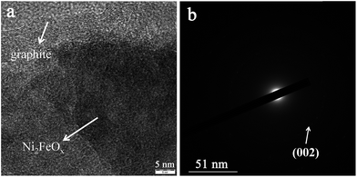
The synthesized samples were characterized by transmission electron microscopy (TEM). For the G-Ph-SO3H support, a clean surface can be observed in the SEM (Fig. S1†) and TEM images (Fig. S2†). For the FeOx@G-Ph-SN sample (Fig. 1a), the FeOx nanoparticles are homogeneously dispersed on the phenylsulfonic acid-functionalized graphite. The histogram in Fig. S3† shows that the majority of the loaded FeOx nanoparticles are around 1.8 nm in diameter. For the NiOx@G-Ph-SN sample (Fig. 1b), the dispersion of NiOx is worse than that of FeOx in FeOx@G-Ph-SN and the particle size increases to ca. 5.7 nm. However, for the Fe and Ni-codoped sample Ni2FeOx@G-Ph-SN (Fig. 1c and d), an amorphous dispersion is typically observed, implying that the FeOx has been alloyed with NiOx. The existence state of NiFeOx in Ni2FeOx@G-Ph-SN was further investigated using the high-resolution TEM image and the SAED pattern. As shown in Fig. 2, no obvious lattice fringes can be observed for the NiFeOx indicating its amorphous form. The ring-shaped diffraction pattern with dispersed bright spots in the SAED pattern can be attributed to the (002) plane of the graphite support. No ring-shaped diffraction pattern due to any crystalline oxides can be observed, further confirming the amorphous structure of NiFeOx.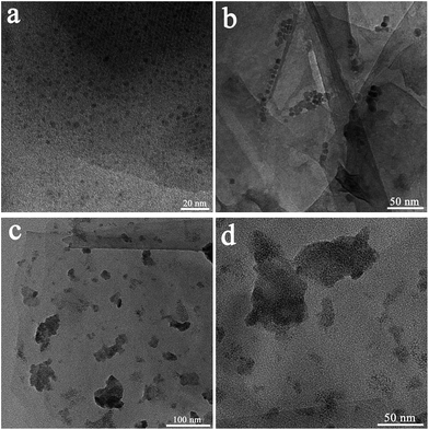 | ||
| Fig. 1 TEM images of the prepared samples: (a) FeOx@G-Ph-SN, (b) NiOx@G-Ph-SN and (c and d) Ni2FeOx@G-Ph-SN. | ||
In addition, no obvious peaks due to FeOx, NiOx, or NiFeOx can be observed in the X-ray powder diffraction (XRD) patterns (Fig. S4†) and Raman spectra (Fig. S5†). The Ni2FeOx@G-Ph-SN possesses a specific BET surface area of 5.8 cm2 g−1, slightly larger than that of graphite (2.3 cm2 g−1) (Fig. S6†). The amorphous NiFeOx in Ni2FeOx@G-Ph-SN can be further evidenced from the SEM image (Fig. 3a). The corresponding energy-dispersive X-ray spectroscopy (EDS) elemental-mapping images of Ni2FeOx@G-Ph-SN in Fig. 3b–f show the distributions of C, Fe, Ni, O, and S, which further verify that Fe and Ni are present in the form of a NiFeOx alloy in Ni2FeOx@G-Ph-SN, since the mapping images of Fe and Ni match very well in the relevant areas.
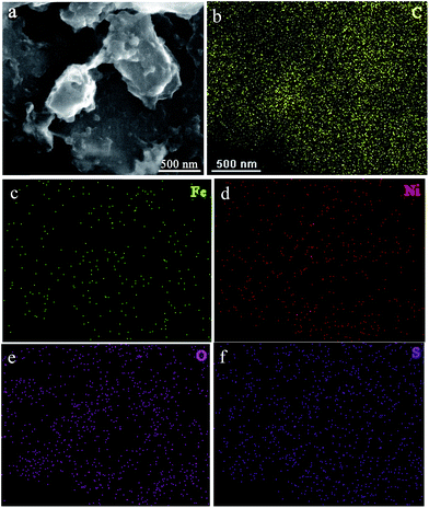 | ||
| Fig. 3 SEM image of Ni2FeOx@G-Ph-SN used in the EDS mapping test (a), and the corresponding EDS mapping of C (b), Fe (c), Ni (d), O (e), and S (f). | ||
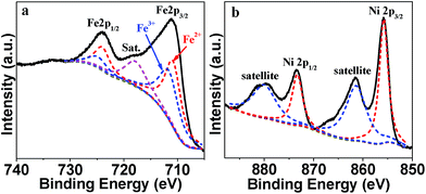
XPS characterization was applied to confirm the chemical valence state of Fe and Ni in Ni2FeOx@G-Ph-SN (Fig. 4). The high-resolution Fe 2p spectrum (Fig. 4a) displays two obvious signals at 711.0 eV for Fe 2p3/2 and 724.1 eV for Fe 2p1/2 along with a satellite peak at 717.8 eV. The Fe 2p3/2 and Fe 2p1/2 spectrum can be fitted into two peaks, respectively. The fitted Fe 2p3/2 at 710.8 eV and Fe 2p1/2 at 724 eV can be attributed to Fe2+,37,38 while the Fe 2p3/2 at 711.6 eV and Fe 2p1/2 at 724.8 eV can be ascribed to Fe3+.39 For the Ni 2p XPS spectrum, the two main peaks observed at 855.85 eV and 873.35 eV with a spin–orbit splitting of ∼17.5 eV are ascribed to Ni2+ 2p1/2 and Ni2+ 2p3/2, respectively (Fig. 4b). Additionally, there are two shakeup satellite peaks at 861.5 and 880.4 eV, implying that Ni exists in the form of Ni2+.37
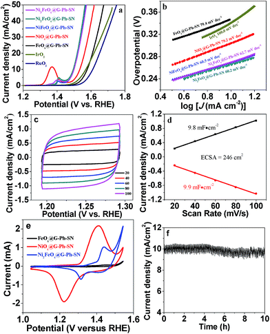
The OER performance of the prepared samples as well as that of IrO2 nanoparticles (Fig. S7,† particle size: 20–30 nm) were evaluated in 1.0 M KOH solution. It can be seen from linear sweep voltammetry (LSV) curves that the potential required to drive a 10 mA cm−2 OER current density on the FeOx@G-Ph-SN catalyst is 1.577 V versus RHE (Fig. 5a), which is slightly higher than that of the IrO2 nanoparticles (1.569 V) and much lower than that of the RuO2 nanoparticles (1.61 V). It has been reported that the OER activity of FeOOH is limited by its low conductivity, and it does not conduct at overpotentials <400 mV.34 However, we found that when the particle size of FeOx is small enough (e.g. ∼1.8 nm), it shows good OER activity at overpotentials <400 mV. Interestingly, the OER activity significantly decreases when increasing the Fe loading content from 4% to 20% (Fig. S8†). The onset potential on 20% FeOx@G-Ph-SN is ca. 1.63 V vs. RHE, which is similar to that observed by Burke et al.34 Therefore, the OER can take place on the extrafine FeOx (e.g. <2 nm), which should be more conductive than larger FeOx particles or sheets.
Meanwhile, the NiOx@G-Ph-SN catalyst exhibits a smaller potential (1.534 V) at a current density of 10 mA cm−2 than FeOx@G-Ph-SN. It is interesting to note that the NiFeOx@G-Ph-SN hybrid presents a lower applied potential (ca. 1.499 V) at an OER current density of 10 mA cm−2 than the individual metal oxide composite. In addition, Ni2FeOx@G-Ph-SN shows the lowest potential at 10 mA cm−2 (1.495 V), which is comparable to those of excellent Fe-/Co-/Ni-based OER electrocatalysts (Table S1†). Besides, it exhibits a lower Tafel slope (60.2 mV dec−1) than that of FeOx@G-Ph-SN (79.4 mV dec−1), NiOx@G-Ph-SN (79.2 mV dec−1), NiFeOx@G-Ph-SN (60.5 mV dec−1), Ni3FeOx@G-Ph-SN (62.7 mV dec−1), and the nanoscale IrO2 catalyst (100 mV dec−1), indicating the excellent OER kinetics of this novel catalyst (Fig. 5b). The Tafel slope of Ni2FeOx@G-Ph-SN is close to 60 mV dec−1, which is associated with a rate-limiting chemical step following the first electron transfer.34,40,41
The electrochemically active surface area (ECSA) of each electrode determined from cyclic voltammetry (CV) curves was compared. The linear slope was obtained by plotting the Δj (|jcharge − joff charge|) in the faradaic silence potential range against the scan rates, and it has a positive correlation with the double-layer capacitance (Cdl), and can be used to represent the corresponding ECSA.42 The NiFe-series samples have higher ECSA compared with the individual metal component samples (Fig. 5c and d and S9†), demonstrating the collaborative contribution from Fe and Ni ions. In addition, among the test samples, Ni2FeOx@G-Ph-SN shows the highest ECSA, which can reach 246 cm2.
The electrochemical impedance spectroscopy (EIS) spectra of FeOx@G-Ph-SN, NiOx@G-Ph-SN and Ni2FeOx@G-Ph-SN were investigated. As shown in Fig. S10,† a semicircle in the high-to-medium frequency region in the Nyquist plots indicates charge transport resistance (Rct), while a straight line in the low frequency range reflects the diffusion resistance (e.g. oxygen desorption on the electrode).13,43 It can be found that FeOx@G-Ph-SN, NiOx@G-Ph-SN and Ni2FeOx@G-Ph-SN have similar Rct, which is due to the good electrical conductivity of the graphite support. However, the slope value of Ni2FeOx@G-Ph-SN in the low frequency range is obviously higher than that of FeOx@G-Ph-SN, indicating faster oxygen desorption on the surface of Ni2FeOx.
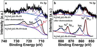
The cyclic voltammogram (CV) of FeOx@G-Ph-SN in 1.0 M KOH at a scan rate of 50 mV s−1 (Fig. 5e) reveals one weak reversible reduction wave at E1/2 = 1.387 versus RHE, ascribed to the one-electron redox reaction of the FeII/FeIII couple.9 Moreover, NiOx@G-Ph-SN shows one strong reversible reduction wave at E1/2 = 1.316 versus RHE, due to the one-electron redox reaction of the NiII/NiIII couple.25,28,44 Interestingly, Ni2FeOx@G-Ph-SN shows one medium reversible reduction wave at E1/2 = 1.377 versus RHE, which falls in between those of FeII/FeIII and NiII/NiIII couples. This indicates that there exists some interaction between Fe and Ni ions in Ni2FeOx@G-Ph-SN, which results in better oxygen evolution behaviour. Although both Ni and Fe are key for OER activity in NiFe-based electrocatalysts, to date no fully consistent view has been reached on which one is the water oxidation active site.31 Our CV results indicate that Ni and Fe interact and co-catalyze water oxidation. In addition to its good electrochemical water oxidation activity, the Ni2FeOx@G-Ph-SN catalyst exhibits high electrochemical stability in alkaline electrolyte (Fig. 5f). After 10 h of continuous operation at a constant anode voltage of 1.5 V vs. RHE in 1.0 M KOH, the current remained almost constant. In addition, the current density of Ni2FeOx@G-Ph-SN at 1.5 V vs. RHE after CV for 200 cycles and 2000 cycles is almost the same, further demonstrating its good electrochemical OER stability (Fig. S11†). The chemical valence state of Fe and Ni in Ni2FeOx@G-Ph-SN after the stability test was analysed by XPS. As shown in Fig. 6, the Fe 2p3/2 at 711.6 eV and Fe 2p1/2 at 724.8 eV may be due to Fe3+ in Ni2FeOx@G-Ph-SN after the stability test, while the Ni 2p XPS peak positions in Ni2FeOx@G-Ph-SN after the stability test are almost the same as those in fresh Ni2FeOx@G-Ph-SN, indicating the same valence state of Ni2+.
Conclusions
In summary, we have demonstrated the fabrication of mixed Ni2FeOx on the surface of sulfonated-graphite by a simple hydrothermal process. The synergistic action of Ni and Fe not only modifies the morphology of the particles, but also enhances the OER activity. The practical application of Ni2FeOx@G-Ph-SN has been demonstrated by its use as a high-efficiency and stable electrocatalyst toward the OER. Our study demonstrates a simple hydrothermal approach for the development of multicomponent metal oxide OER catalysts.Conflicts of interest
There are no conflicts to declare.Acknowledgements
This work was supported by the National Natural Science Foundation of China (21303069) and Natural Science Foundation of Jilin Province (20150520013JH and 20180101291JC).Notes and references
- V. Vij, S. Sultan, A. M. Harzandi, A. Meena, J. N. Tiwari, W. G. Lee, T. Yoon and K. S. Kim, ACS Catal., 2017, 7, 7196 CrossRef
.
- X. Li, J. Yu, S. Wageh, A. A. Al-Ghamdi and J. Xie, Small, 2016, 12, 6640 CrossRef PubMed
.
- C. Spoeri, J. T. H. Kwan, A. Bonakdarpour, D. P. Wilkinson and P. Strasser, Angew. Chem., Int. Ed., 2017, 56, 5994 CrossRef PubMed
.
- B. M. Hunter, H. B. Gray and A. M. Muller, Chem. Rev., 2016, 116, 14120 CrossRef PubMed
.
- J. Ramon Galan-Mascaros, ChemElectroChem, 2015, 2, 37 CrossRef
.
- K. Liu, H. Zhong, F. Meng, X. Zhang, J. Yan and Q. Jiang, Mater. Chem. Front., 2017, 1, 2155 RSC
.
- D. B. Rice, A. A. Massie and T. A. Jackson, Acc. Chem. Res., 2017, 50, 2706 CrossRef PubMed
.
- B. Zhang, X. L. Zheng, O. Voznyy, R. Comin, M. Bajdich, M. Garcia-Melchor, L. L. Han, J. X. Xu, M. Liu, L. R. Zheng, F. P. G. de Arquer, C. T. Dinh, F. J. Fan, M. J. Yuan, E. Yassitepe, N. Chen, T. Regier, P. F. Liu, Y. H. Li, P. De Luna, A. Janmohamed, H. L. L. Xin, H. G. Yang, A. Vojvodic and E. H. Sargent, Science, 2016, 352, 333 CrossRef PubMed
.
- M. Okamura, M. Kondo, R. Kuga, Y. Kurashige, T. Yanai, S. Hayami, V. K. K. Praneeth, M. Yoshida, K. Yoneda, S. Kawata and S. Masaoka, Nature, 2016, 530, 465 CrossRef PubMed
.
- G. Liu, P. Li, G. Zhao, X. Wang, J. Kong, H. Liu, H. Zhang, K. Chang, X. Meng, T. Kako and J. Ye, J. Am. Chem. Soc., 2016, 138, 9128 CrossRef PubMed
.
- C. Huang, T. Ouyang, Y. Zou, N. Li and Z.-Q. Liu, J. Mater. Chem. A, 2018, 6, 7420 RSC
.
- G.-F. Chen, T. Y. Ma, Z.-Q. Liu, N. Li, Y.-Z. Su, K. Davey and S.-Z. Qiao, Adv. Funct. Mater., 2016, 26, 3314 CrossRef
.
- L. Tian, X. Yan, X. Chen, L. Liu and X. Chen, J. Mater. Chem. A, 2016, 4, 13011 RSC
.
- X. Yan, L. Tian, J. Murowchick and X. Chen, J. Mater. Chem. A, 2016, 4, 3683 RSC
.
- L. Tian, J. Murowchick and X. Chen, Sustainable Energy Fuels, 2017, 1, 62 RSC
.
- T. Liu, L. Xie, J. Yang, R. Kong, G. Du, A. M. Asiri, X. Sun and L. Chen, ChemElectroChem, 2017, 4, 1840 CrossRef
.
- Q. Liu, L. Xie, Z. Liu, G. Du, A. M. Asiri and X. Sun, Chem. Commun., 2017, 53, 12446 RSC
.
- M. Xie, X. Xiong, L. Yang, X. Shi, A. M. Asiri and X. Sun, Chem. Commun., 2018, 54, 2300 RSC
.
- X. Ji, R. Zhang, X. Shi, A. M. Asiri, B. Zheng and X. Sun, Nanoscale, 2018, 10, 7941 RSC
.
- M. Bajdich, M. Garcia-Mota, A. Vojvodic, J. K. Norskov and A. T. Bell, J. Am. Chem. Soc., 2013, 135, 13521 CrossRef PubMed
.
- Y. Yang, H. Fei, G. Ruan and J. M. Tour, Adv. Mater., 2015, 27, 3175 CrossRef PubMed
.
- X. Gao, H. Zhang, Q. Li, X. Yu, Z. Hong, X. Zhang, C. Liang and Z. Lin, Angew. Chem., Int. Ed., 2016, 55, 6290 CrossRef PubMed
.
- R. D. L. Smith, M. S. Prevot, R. D. Fagan, S. Trudel and C. P. Berlinguette, J. Am. Chem. Soc., 2013, 135, 11580 CrossRef PubMed
.
- J. Xie, H. Zhang, S. Li, R. Wang, X. Sun, M. Zhou, J. Zhou, X. W. Lou and Y. Xie, Adv. Mater., 2013, 25, 5807 CrossRef PubMed
.
- L. Trotochaud, S. L. Young, J. K. Ranney and S. W. Boettcher, J. Am. Chem. Soc., 2014, 136, 6744 CrossRef PubMed
.
- G. Liu, R. Yao, Y. Zhao, M. Wang, N. Li, Y. Li, X. Bo, J. Li and C. Zhao, Nanoscale, 2018, 10, 3997 RSC
.
- X. Chen, P. Gao, H. Liu, J. Xu, B. Zhang, Y. Zhang, Y. Tang and C. Xiao, Electrochim. Acta, 2018, 267, 8 CrossRef
.
- P. Zhang, L. Li, D. Nordlund, H. Chen, L. Fan, B. Zhang, X. Sheng, Q. Daniel and L. Sun, Nat. Commun., 2018, 9, 381 CrossRef PubMed
.
- J. Zhao, X. Li, G. Cui and X. Sun, Chem. Commun., 2018, 54, 5462 RSC
.
- F. Song and X. L. Hu, Nat. Commun., 2014, 5, 4477 CrossRef PubMed
.
- W. Yang, K. Zhu and X. Zhu, Angew. Chem., Int. Ed., 2018 DOI:10.1002/anie.201802923
.
- M. Gao, W. Sheng, Z. Zhuang, Q. Fang, S. Gu, J. Jiang and Y. Yan, J. Am. Chem. Soc., 2014, 136, 7077 CrossRef PubMed
.
- J. Y. C. Chen, L. Dang, H. Liang, W. Bi, J. B. Gerken, S. Jin, E. E. Alp and S. S. Stahl, J. Am. Chem. Soc., 2015, 137, 15090 CrossRef PubMed
.
- M. S. Burke, M. G. Kast, L. Trotochaud, A. M. Smith and S. W. Boettcher, J. Am. Chem. Soc., 2015, 137, 3638 CrossRef PubMed
.
- K. Zhu, H. Liu, M. Li, X. Li, J. Wang, X. Zhu and W. Yang, J. Mater. Chem. A, 2017, 5, 7753 RSC
.
- D. Friebel, M. W. Louie, M. Bajdich, K. E. Sanwald, Y. Cai, A. M. Wise, M. J. Cheng, D. Sokaras, T. C. Weng, R. Alonso-Mori, R. C. Davis, J. R. Bargar, J. K. Norskov, A. Nilsson and A. T. Bell, J. Am. Chem. Soc., 2015, 137, 1305 CrossRef PubMed
.
- Y. Liu, Y. Bai, Y. Han, Z. Yu, S. Zhang, G. Wang, J. Wei, Q. Wu and K. Sun, ACS Appl. Mater. Interfaces, 2017, 9, 36917 CrossRef PubMed
.
- J. Yang, X. Wang, B. Li, L. Ma, L. Shi, Y. Xiong and H. Xu, Adv. Funct. Mater., 2017, 27, 1606497 CrossRef
.
- Z. Wu, X. Wang, J. Huang and F. Gao, J. Mater. Chem. A, 2018, 6, 167 RSC
.
- D. K. Bediako, C. Costentin, E. C. Jones, D. G. Nocera and J.-M. Saveant, J. Am. Chem. Soc., 2013, 135, 10492 CrossRef PubMed
.
- Y. Surendranath, M. W. Kanan and D. G. Nocera, J. Am. Chem. Soc., 2010, 132, 16501 CrossRef PubMed
.
- H. Fei, J. Dong, M. J. Arellano-Jimenez, G. Ye, N. D. Kim, E. L. G. Samuel, Z. Peng, Z. Zhu, F. Qin, J. Bao, M. J. Yacaman, P. M. Ajayan, D. Chen and J. M. Tour, Nat. Commun., 2015, 6, 8668 CrossRef PubMed
.
- S. Ci, Z. Wen, J. Chen and Z. He, Electrochem. Commun., 2012, 14, 71 CrossRef
.
- J. R. Swierk, S. Klaus, L. Trotochaud, A. T. Bell and T. D. Tilley, J. Phys. Chem. C, 2015, 119, 19022 CrossRef
.
Footnote |
| † Electronic supplementary information (ESI) available. See DOI: 10.1039/c8se00307f |
| This journal is © The Royal Society of Chemistry 2018 |

