
Contribution of electrolyte in nanoscale electrolysis of pure and buffered water by particulate photocatalysis†
Muhammad
Qureshi
 a,
Angel T.
Garcia-Esparza‡
b,
Tatsuya
Shinagawa§
a,
Philippe
Sautet
cd,
Tangui
Le Bahers
b and
Kazuhiro
Takanabe
*a
a,
Angel T.
Garcia-Esparza‡
b,
Tatsuya
Shinagawa§
a,
Philippe
Sautet
cd,
Tangui
Le Bahers
b and
Kazuhiro
Takanabe
*a
aKing Abdullah University of Science and Technology (KAUST), KAUST Catalysis Center (KCC), Physical Sciences and Engineering Division, 4700 KAUST, Thuwal, 23955-6900, Saudi Arabia
bUniv Lyon, ENS de Lyon, CNRS, Université Claude Bernard Lyon 1, Laboratoire de Chimie UMR 5182, F-69342 Lyon, France
cDepartment of Chemical and Biomolecular Engineering, University of California Los Angeles (UCLA), Los Angeles, CA 90095, USA
dDepartment of Chemistry and Biochemistry, University of California Los Angeles, Los Angeles, CA 90095, USA
First published on 29th June 2018
Abstract
Photocatalysis using semiconductor powders in suspension performs reduction and oxidation reactions at nanometer-scale distances. Such short distances between the reduction (cathode) and the oxidation (anode) sites enable photocatalytic water splitting to generate H2 and O2 from pure water without a supporting electrolyte, which is otherwise impossible in conventional electrode systems due to the high solution resistance. A CrOx/Pt/SrTiO3 model photocatalyst achieves high efficiency under UV irradiation in ultra-pure water splitting at rates (>1 μmol-H2 per cm2 per h) corresponding to electrocatalysis on the order of mA cm−2. The introduction of an unbuffered supporting electrolyte did not improve the photocatalytic rates, consistent with the negligible ohmic losses (<1 mV) numerically calculated using the Poisson–Nernst–Planck equations. The Nernstian potential loss resulting from pH gradients became apparent at high photocatalytic rates (>100 mV when rate >1 μmol-H2 per cm2 per h) even when the distance between redox sites was below 10 nm. Substantial improvements in photocatalytic rates were observed when buffer ions were introduced into near-neutral pH media by not only circumventing pH gradients but introducing kinetically facile H+ reduction to H2 instead of the kinetically sluggish direct reduction of H2O to H2. Herein, the quantitative descriptions of the electric potential, concentration gradients, and catalytic performance in nanoscale water electrolysis are presented with emphasis on (1) the advantages of performing redox reactions at the nanoscale, (2) the use of electrolyte engineering at near-neutral pH as a universal and effective strategy, and (3) the effectiveness of transferring knowledge from electrocatalysis to photocatalysis, where the potential is quantitatively defined regarding the former and poorly quantified regarding the latter.
Introduction
Photocatalysis using semiconductor powders, particularly when decorated with metal particles, enables both reduction and oxidation reactions utilizing the local charge separation of photo-excited carriers. In its most basic form, the particulate photocatalytic system is classically described as an assembly of microphotoelectrochemical cells.1–3 Such photocatalytic materials are applicable to the overall water-splitting reaction, which has been examined since the 1970s.4 High apparent quantum efficiencies (AQEs) have been achieved using UV-responsive photon absorbers, including Al-doped SrTiO3.5–7 Generally, successful photocatalytic overall water splitting is realized with hydrogen-evolving electrocatalysts, the surfaces of which are often decorated by thin films with a membrane-like function, e.g., CrOx, that avoid the water-forming back reaction.8,9 The powders achieving overall water splitting are herein considered water electrolyzers at the nanoscale (<100 nm). Such nanosystems are substantially different from conventional electrode redox systems in terms of the local electric field, the ohmic loss, and the role of supporting ions in steady-state catalysis; thus, the overall picture of the reactions differs considerably from conventional electrochemistry where the electrodes are comparatively far apart (>μm).Comprehensive studies dedicated to the fundamental understanding of the photocatalytic system are essential to identify the factors limiting the performance for the following complex physicochemical processes: (1) photon absorption, (2) exciton separation, (3) charge diffusion, (4) charge transfer, (5) surface catalysis, and (6) mass transport of reactants.10,11 Successful photocatalysis requires all these processes to function simultaneously and harmoniously for both cathodic and anodic reactions, which makes the realization of such a system challenging. A promising approach is the decoupling of the physicochemical processes to study each involved step separately. In particular, when multielectron processes with sufficiently long timescales are involved in the surface catalysis, such as H2 and O2 evolution, it is effective to utilize electrochemical measurements to separately elucidate the surface redox reactions. While an electrochemical configuration can be effectively utilized to pin down the potential of photon absorber and its contact with electrode,12,13 the potential of powder photocatalysts in a suspension form is difficult to quantify because some surfaces must be charged up negatively and/or positively to achieve steady-state redox reactions.14,15 In this way, the knowledge obtained from the quantitative study of electrocatalysis can be transferred to photocatalysis, which provides key insights for the photocatalytic systems.
Recently, theoretical multiphysics models were used to quantitatively drive the design and optimization of macroscale water-splitting devices on the order of the micro- to centimeter scale,16–23 which indicated the following as limiting factors: ohmic losses, potential losses from pH gradients, mass transport, and product crossover.18,19,23–25 These findings led to the proposal of new concepts for improving system efficiency, for example, the optimization of the reactor's geometry18 and the design of dynamic flow systems for on-site gas separation.26 In contrast, nanoscale electrolysis is expected not to suffer from the aforementioned macroscale limitations.27 Theoretical models for such illuminated semiconductor particles impregnated with electrocatalysts are scarce but crucial to drive the research in the field.28–32
In this context, we consider photocatalytic water splitting as nanoscale water electrolysis driven by photocatalyst particulates. Photo- and electrocatalytic measurements combined with theoretical simulations are performed to quantify the extent to which nanoscale electrolysis is advantageous over conventional macroscale electrolysis. More specifically, potential losses associated with surface kinetics, diffusion, and migration phenomena in nanometer-sized domains are quantitatively described. The nanoelectrochemistry disclosed in this study is correlated with the development of applications in fields ranging from energy to bioanalysis.33–37
Methods
Electrocatalysis
All electrochemical measurements were recorded using a research-grade BioLogic VMP3 potentiostat. A conventional single-compartment three-electrode system was used for the electrochemical protocols, where a Pt wire and an Ag/AgCl (saturated with KCl) were used as a counter and a reference electrode, respectively. Before and during the measurements, Ar (99.9999%), H2 (99.9999%), or O2 (99.9995%) was continuously supplied through the electrolyte under vigorous stirring. Cyclic and linear sweep voltammograms were recorded at a scan rate of 50 mV s−1 at room temperature. All reported potentials are iR-corrected (i.e., ohmic drop) and presented with reference to the reversible hydrogen electrode (RHE). A CrOx/Pt rotating disk-electrode (RDE) was used unless otherwise stated. Before CrOx deposition, a Pt disk electrode (3.0 mm diameter, 0.071 cm2 geometric surface area; purchased from BAS, Inc.) was first polished with 1 μm diamond and then with 0.05 μm alumina (BAS, Inc.). CrOx was deposited on the Pt RDE by chronopotentiometry (CP; −20 μA for 10 min with Ar bubbling) under static conditions in a 0.5 M K2CrO4 solution (pH = 9.7).9Photocatalysis
The synthesis of SrTiO3 was carried out as previously reported.5 Briefly, SrTiO3 and SrCl2 at a molar ratio of 1![[thin space (1/6-em)]](https://www.rsc.org/images/entities/char_2009.gif) :5 were ground up with a mortar and pestle for 25 min followed by a flux treatment at 1273 K for 10 h to generate highly crystalline SrTiO3. The powder was then washed with water until no more chloride salt was detected by the AgNO3 test. Pt nanoparticles were deposited on the surface of SrTiO3via wet impregnation for a calculated metal loading of 0.5 wt%. Na2PtCl6·6H2O (0.1 M solution) was mixed with 100 mg of SrTiO3 in 5 mL of water over a water bath until all the water evaporated. The powder was collected by filtration, calcined at 573 K for 1 h and then used for the photocatalytic reaction. CrOx was deposited on Pt/SrTiO3 by photodeposition, where 50 mg of Pt/SrTiO3 was dispersed by sonication in 100 mL of 2 mM K2CrO4 solution, which was then placed in a photoreactor and irradiated for 6 h. The error bars were calculated based on the standard deviation for three separate photocatalytic tests utilizing a pristine sample with a new solution each time. The photocatalytic reactions were conducted at 100 Torr Ar gas in a circulating batch reactor (total volume of 515 mL) equipped with an online gas chromatograph (GC: Bruker 450 GC, TCD, Ar gas, molecular sieve 13X) connected to a vacuum line. Two Xe lamps (CERMAX PE300-BF and PE300-BUV, 300 W) were used as the light source, and the irradiation wavelength was controlled with a combination of a cold mirror and a water filter (300 < λ < 800 nm). To further control the photon flux, the neutral density filters (5 × 5 cm2, 2.5 mm thick, HOYA Optics, ND-13, -25, -50, -70) were used. The spectral area of the photocatalytic reactor was 38.5 cm2, and the photon flux was measured using the AvaSpec-3648 spectrometer, an AvaLight DHS calibration light source, and a FC-UV200-2 fiber-optic cable. The AQE measurements were conducted with a 350 nm bandpass filter at different time points in the experiment.
:5 were ground up with a mortar and pestle for 25 min followed by a flux treatment at 1273 K for 10 h to generate highly crystalline SrTiO3. The powder was then washed with water until no more chloride salt was detected by the AgNO3 test. Pt nanoparticles were deposited on the surface of SrTiO3via wet impregnation for a calculated metal loading of 0.5 wt%. Na2PtCl6·6H2O (0.1 M solution) was mixed with 100 mg of SrTiO3 in 5 mL of water over a water bath until all the water evaporated. The powder was collected by filtration, calcined at 573 K for 1 h and then used for the photocatalytic reaction. CrOx was deposited on Pt/SrTiO3 by photodeposition, where 50 mg of Pt/SrTiO3 was dispersed by sonication in 100 mL of 2 mM K2CrO4 solution, which was then placed in a photoreactor and irradiated for 6 h. The error bars were calculated based on the standard deviation for three separate photocatalytic tests utilizing a pristine sample with a new solution each time. The photocatalytic reactions were conducted at 100 Torr Ar gas in a circulating batch reactor (total volume of 515 mL) equipped with an online gas chromatograph (GC: Bruker 450 GC, TCD, Ar gas, molecular sieve 13X) connected to a vacuum line. Two Xe lamps (CERMAX PE300-BF and PE300-BUV, 300 W) were used as the light source, and the irradiation wavelength was controlled with a combination of a cold mirror and a water filter (300 < λ < 800 nm). To further control the photon flux, the neutral density filters (5 × 5 cm2, 2.5 mm thick, HOYA Optics, ND-13, -25, -50, -70) were used. The spectral area of the photocatalytic reactor was 38.5 cm2, and the photon flux was measured using the AvaSpec-3648 spectrometer, an AvaLight DHS calibration light source, and a FC-UV200-2 fiber-optic cable. The AQE measurements were conducted with a 350 nm bandpass filter at different time points in the experiment.
Characterization
Transmission electron microscopy (TEM) analysis was performed using a probe-corrected microscope operated at an accelerating voltage of 300 kV. The microscope was a Titan 80-300 ST from FEI Company (Hillsboro, OR) equipped with a GIF-Quantum 966 image filter from Gatan, Inc. Diffuse reflectance UV-vis spectroscopy was performed using a JASCO model V-670 spectrophotometer equipped with an integrating sphere, referencing a Spectralon standard (Labsphere, Inc.).Theoretical model
The PNP model was numerically solved via finite element analysis in a two-dimensional domain with COMSOL Multiphysics using equilateral triangular mesh elements (see Fig. S4 and the simulation parameters in Table S1†). The conventional planar diffusion model has been considered, and the discussion is presented in the ESI, Fig. S11 and S12.†In general, an electric field originating from the charge density may be described using Gauss's law (∇·D = ρc). In electrochemistry, we may assume a constant permittivity of the electrolyte (D = ε0εrE = −ε0εr∇ϕ). In the electrolyte, the charge density (ρc) is the summation of ionic charge carriers. The Poisson equation (eqn (1)) describes the potential (ϕ) as a function of the distribution and concentration (ci) of the ionic charge carriers in the electrolyte of constant isotropic permittivity (εr):
 | (1) |
 | (2) |
 | (3) |
For the kinetic contribution, the Tafel relation was utilized to represent the overpotential (η) as a function of the overall current density in the system (jT) for the HER and OER charge transfer reactions.
| η = a + blogjT | (4) |
A constant Tafel slope (b) of 120 mV dec−1 was used for the kinetics of both electrocatalytic reactions.41 The HER exchange current density parameters (10−a/b) under unbuffered and buffered conditions were set at 1 × 10⁻² and 3 mA cm−2, respectively, derived from the Tafel analysis of the CrOx/Pt RDE via CV in a H2 atmosphere (Fig. S8†). The OER exchange current density was obtained from the literature (2 × 10⁻³ mA cm−2).42 Table S1† summarizes the simulation parameters used for the numerical simulations.
Results and discussion
When photonic efficiency is of concern, reaction rate or current density is effectively comparable when these are normalized per illuminated geometric area (e.g., μmol cm−2 h−1 or mA cm−2, respectively) while specifying photon flux. Recent advances in photocatalytic powder suspension systems have achieved redox reactions on the nanoscale at rates operated in typical electrochemical measurements. The correlation of the photocatalytic H2 evolution rate with electrocatalytic current density is described in Fig. S1.† For example, photocatalytic overall water splitting to evolve H2 now overcomes the efficiency of natural photosynthesis (∼0.1%) in terms of solar-to-hydrogen (STH) energy conversion efficiency.6 The energy efficiency losses in photocatalytic systems are quantitatively described by isolating the solution resistance (ohmic loss), concentration (pH) gradients (concentration overpotential), and electrocatalytic kinetics (kinetic overpotential).Photocatalytic water splitting under unbuffered near-neutral pH conditions
Highly crystalline SrTiO3 was decorated with Pt electrocatalyst that was used for hydrogen evolution reaction (HER). The exposed SrTiO3 surface (specific if not all) was regarded to electrocatalyze oxygen evolution reaction (OER).42–44 The surfaces of the Pt catalysts were coated with Cr species to mitigate the activation of the water-forming back-reactions, i.e., both the electrochemical back reaction (O2 reduction reaction) and the H2/O2 thermal recombination (see Fig. S2†).8,9 The flux-assisted synthesis of SrTiO3 (ref. 5) and the function of the Cr layer8,9,45 on Pt have been reported in detail elsewhere. The transmission electron micrographs in Fig. 1 show the geometry of the synthesized CrOx/Pt (0.41 wt%)/SrTiO3 (see Fig. S3† for the optimization of the metal loading). Microscopy revealed that the average particle size of SrTiO3 was 150–500 nm. The size of the CrOx/Pt electrocatalysts was 3 ± 1 nm with an average inter-particle distance of 5 ± 4 nm (i.e., Pt to Pt distance), and the nanoparticles were homogeneously dispersed on the SrTiO3 surface. Using this photocatalytic system as a model system, we attempt to quantitatively elucidate potential losses associated with nanoscale electrolysis. | ||
| Fig. 1 Transmission electron micrographs of CrOx/Pt (0.41 wt%)/SrTiO3 on two different scales (A, B) after the photocatalytic water splitting reaction in 18.2 MΩ cm, pH 6.8. (B) Inset shows a bare SrTiO3 sample with a scale bar of 5 nm. | ||
With respect to the solution resistance, in a conventional macroscale electrochemical system, the splitting of ultra-pure water requires a significantly large overpotential because of the low conductivity of the solution, and thus, the use of supporting inert ions to increase the conductivity of the solution is required. In stark contrast, the photocatalytic powder system successfully achieves the splitting of ultra-pure water (18.2 MΩ cm, corresponding to 5.5 × 10⁻⁶ S m−1) as demonstrated in Fig. 2, stably generating H2 and O2 with a 2 to 1 ratio for 10 h. Furthermore, the photocatalytic performance in a 0.5 M K2SO4 solution (pH 6, unbuffered) was similar to that in ultra-pure water (Fig. 2), consistent with negligible solution resistance in the photocatalytic system.
 | ||
| Fig. 2 Photocatalytic overall water splitting activity time course of CrOx/Pt/SrTiO3 in ultra-pure water and 0.5 M potassium sulfate (300 < λ < 800 nm, 50 mg of photocatalyst, 100 mL solution, 38.5 cm2 irradiated area). | ||
To complement the experimental observation on the negligible ohmic loss in nanoscale electrolysis, simulations of the electrolysis of ultra-pure water (i.e., photocatalytic overall water splitting) solving the Poisson–Nernst–Planck (PNP) equations for the concentration of H+ and OH−, the flux of the ionic species, and the potential and current distributions in the solution were performed by controlling the gas evolution rates (Fig. S4, Table S1†). Fig. 3A–C describe the two-dimensional diagrams of the potential drop due to solution resistance, and Fig. 3D provides a summary of the ohmic drop for distances between 5 and 110 nm. The trend indicates a minimal potential drop (typically <1 mV) when the electrolysis of ultra-pure water occurred at distances shorter than 40 nm at rates of 1–100 μmol-H2 per cm2 per h. Ultra-pure water (σl < 10−5 S m−1) roughly exhibits a conductivity four to five orders of magnitude smaller than conductive supporting electrolytes (e.g., 0.5 M Na2SO4, σl ≈ 10−1 S m−1).46 Nevertheless, it appears that improving the conductivity of the solution does not significantly contribute to improvements in the overall efficiency. Furthermore, on larger scales (>μm), the ohmic drop could easily reach values larger than 100 mV in Milli-Q water (σl = 5.5 × 10⁻⁶ S m−1) when using simplified simulations performed to validate our results following the work of Haussener et al. (Fig. S5†),18 which emphasizes the benefit of nanoscale water electrolysis.
 | ||
| Fig. 3 Nanoscale electrolysis simulations in ultra-pure water at pH 7 under a constant overall rate of 1 μmol-H2 per cm2 per h where the HER and OER redox sites are r = 3 nm in size and inter-particle distances of (A) 5 nm, (B) 40 nm, and (C) 80 nm. The isopotential color gradients indicate the solution of the PNP equations, specifically the potential distribution in the solution representing the potential drop across the liquid domain. The white arrows qualitatively represent the normalized flux of H+ in the electrolyte. (D) A summary of the ohmic drop as a function of photocatalytic H2 rate from inter-particle distances ranging from 5 to 110 nm. | ||
Using the same computational framework, the pH gradient caused by redox reactions is also addressed. Potential loss due to pH gradients causes an additional overpotential of 59 mV per pH unit (derived from the Nernst equation). The resulting pH trends from water electrolysis at a 5 nm distance are presented in Fig. 4A–C over three orders of magnitude in photocatalytic rates (1.5–150 μmol-H2 per cm2 per h). The computations showed that ultra-pure water splitting or, more generally, water splitting under unbuffered conditions at near neutral pH suffered from pH gradients close to the redox-active surfaces when the reaction occurred at higher rates (Fig. 4D). At relevant photocatalytic rates, such as achieving 10% STH efficiency or ≈153 μmol-H2 per cm2 per h (see Fig. S1†), Nernstian potential losses due to the pH gradients could easily reach 100 mV or more, even if a 5 nm distance is used. Therefore, photocatalytic water splitting under conventional near-neutral pH conditions even on the nanoscale is largely hindered by the accumulation of generated H+ and OH− at the proximity of the active sites, which adds substantial overpotential to the system.
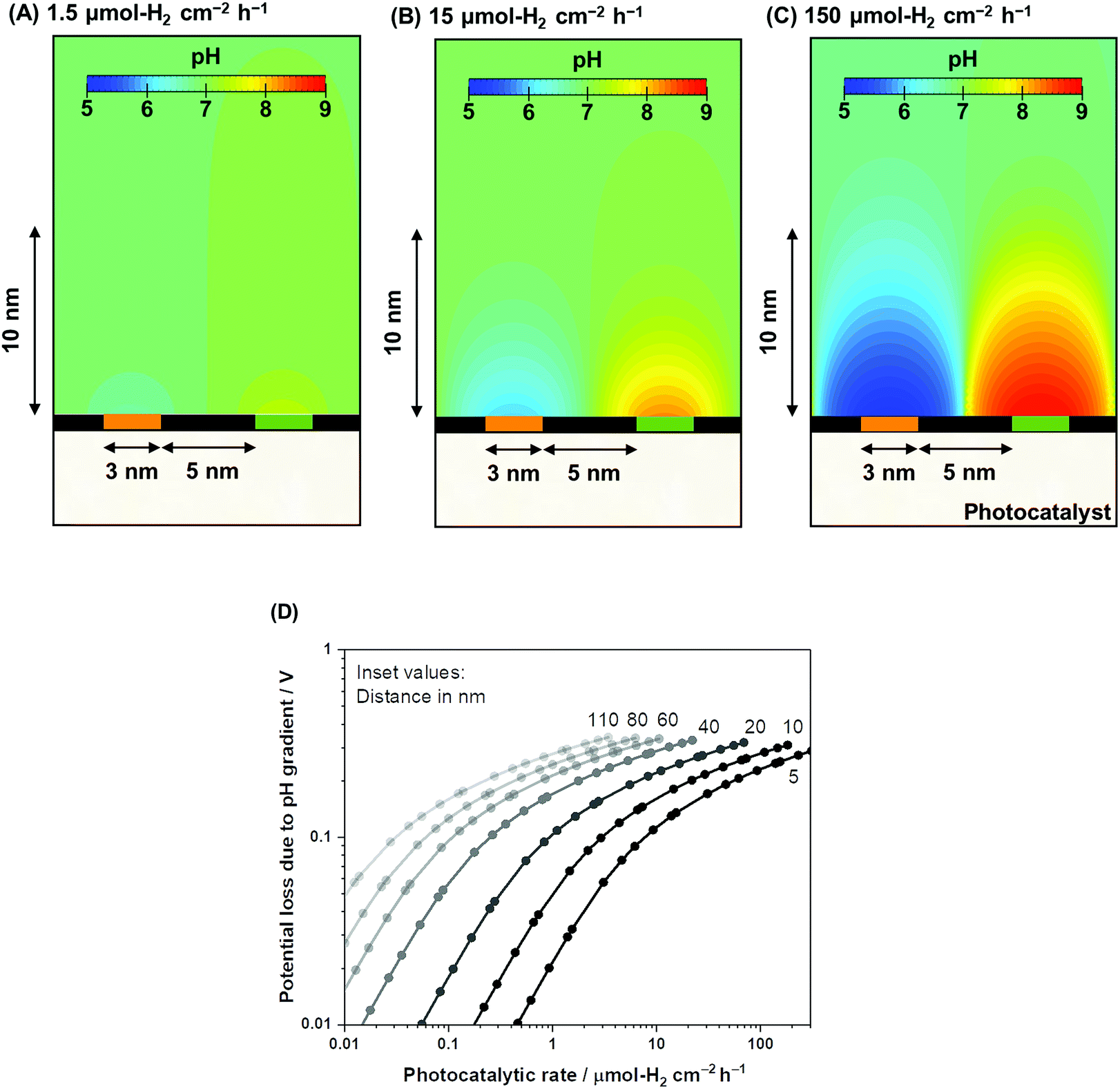 | ||
| Fig. 4 Nanoscale electrolysis mass transport simulations in ultra-pure water at pH 7 under photocatalytic H2 evolution rates of (A) 1.5, (B) 15, and (C) 150 μmol-H2 per cm2 per h. The isosurface color gradients indicate the pH of the solution in the 2D model. A 5 nm inter-particle distance was assumed between the HER and OER redox sites. (D) A summary of the Nernstian potential loss resulting from the pH gradient as a function of the photocatalytic H2 rate from inter-particle distances ranging from 5 to 110. | ||
Photocatalytic water splitting under buffered near-neutral pH conditions
The disclosed limiting factor inherent to photocatalytic water splitting at near-neutral pH leads to one strategy to improve its performance: the utilization of buffering action. The impact of buffer ions on photocatalytic performance is evident from Fig. 5, where the AQE for photocatalytic overall water splitting using CrOx/Pt/SrTiO3 is compared in unbuffered (0.5 M K-sulfate) and buffered (0.5 M K-phosphate) conditions over a wide pH range of 4–14. The presence of buffer at pH 4–10 unequivocally improved the photocatalytic performance by two-fold at near-neutral pH. We observe that the performances in 0.5 M KHCO3 (pH 8.5) and 0.5 M K-borate buffers (pH 9.6, 20% KOH, 80% H3BO3) also gave improved performance when compared at the same pH values. Acidic conditions lower than pH 4 could not be studied because of CrOx dissolution.47 The rate was almost insensitive to the presence or absence of buffer species at pH 12. Overall, these observations show that the introduction of buffering action indeed substantially improves the photocatalytic overall water splitting performance in the near-neutral pH region (4 ≤ pH ≤ 10), making it comparable or even slightly superior to the performance at pH 14.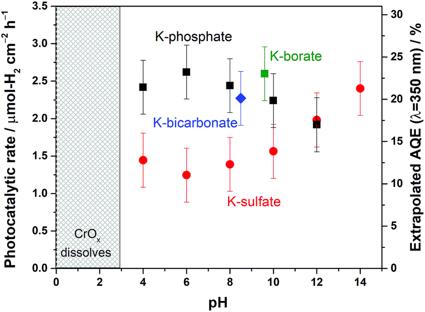 | ||
| Fig. 5 (Left Y-axis) Photocatalytic overall water splitting rate represented by H2 evolution rate and (Right Y-axis) AQE of CrOx/Pt/SrTiO3 in 0.5 M potassium sulfate solution (unbuffered) at various pH values, 0.5 M potassium phosphate solution (buffered) at various pH values, 0.5 M K-bicarbonate (buffered), and 0.5 M K-borate (buffered) (50 mg of photocatalyst, 100 mL solution, 38.5 cm2 irradiated area). | ||
To confirm the effects of buffer ions on pH alteration and the resultant kinetics, photocatalytic tests were performed using hole or electron scavengers to separately investigate the HER and OER half-reactions. If the buffer exclusively minimizes pH alteration, both HER and OER half-reactions should be equally improved in the presence of a buffer. If a buffer contributes to the kinetics of the reactions, a significant improvement in the performance in such half-reactions should be observed using a buffer. Fig. 6 presents the rate of gas evolution over Pt/SrTiO3 using a hole scavenger of CH3OH or an electron scavenger of IO3− in 0.5 M K-sulfate and K-phosphate solutions (see Fig. S6† for the photocatalytic activity time course). In the presence of CH3OH, a rate of 5.5 μmol-H2 per cm2 per h for the HER was achieved in sulfate, corresponding to an AQE of 48 ± 2% at 350 nm, which was significantly improved to 7.6 μmol-H2 per cm2 per h in phosphate solution, corresponding to an AQE of 67 ± 2% (Fig. 6). In contrast, such an improvement by the introduction of buffer was minimal when IO3− was used as the electron donor to study OER (1.9 vs. 2.2 μmol-O2 per cm2 per h in sulfate and phosphate solutions, respectively). Hence, it can be concluded that the buffer ions do not simply minimize the pH gradient but also improve the HER process.
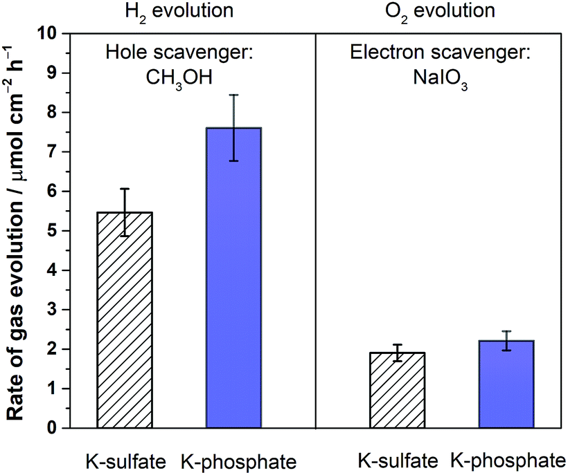 | ||
| Fig. 6 Photocatalytic H2 and O2 evolution rates of Pt/SrTiO3 in 0.5 M potassium sulfate solution (unbuffered) and 0.5 M potassium phosphate solution (buffered) at pH 6 using either 5% CH3OH solution or 100 mM NaIO3 solution as a hole or an electron scavenger, respectively (300 < λ < 800 nm, 50 mg of photocatalyst, 100 mL solution, 38.5 cm2 irradiated area). | ||
The electrochemical performance of a model CrOx/Pt electrode was used to investigate the HER catalytic performance in various electrolytes. Although the model electrode system used here does not fully replicate the complicated and undefined environment of the complex photocatalytic system, the results would highlight the role of electrolyte in an extreme convection mode at near-neutral pH conditions. We performed cyclic voltammetry (CV) utilizing the rotating disk electrode (RDE) to regulate the diffusion flux in the system. Fig. 7 shows the absolute current density as a function of overpotential at pH 4. Fig. 7 shows that the unbuffered conditions showed a two-step reduction. The first reduction is attributable to proton reduction, which became diffusion limited, consistent with a macroscopic calculation of the theoretical diffusion flux of protons (Fig. S7†) and the previous literature.41,48 The second reduction process observed at a more negative potential was ascribed to the reduction of the water molecule, consistent with the constant overpotential among different pH on the standard hydrogen electrode scale (SHE), as shown in Fig. S8.†41 The HER currents in the presence of phosphate buffer (Fig. 7) show a monotonic increase with overpotential, indicating that protons were successfully supplied by the buffering ions.41 These electrocatalytic measurements confirm that the introduction of buffer species to the system improved the performance not only by mitigating the local pH alteration but also by maintaining kinetically facile proton reduction instead of the kinetically slow H2O reduction (O–H dissociation).
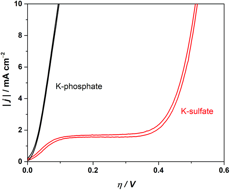 | ||
| Fig. 7 Cyclic voltammograms in 0.5 M potassium sulfate solution (unbuffered) and 0.5 M potassium phosphate solution (buffered) using the CrOx/Pt RDE (at 50 mV s−1, 3600 rpm, with H2 bubbling, 298 K). | ||
The ion mass transport limitations depend on the current density and extent of convection in the electrochemical configuration (Fig. S7†). Likewise, the mass transport contributions in the photocatalytic experiments should be only observable when highly efficient photocatalysts are employed at high rates of reaction49,50 and/or high photon flux is used until the rate is exclusively determined by the upper limit of quantum yields. The photocatalytic rate of CrOx/Pt/SrTiO3 was correlated with the light intensity under unbuffered and buffered conditions at pH 4. The results are shown in Fig. 8. The light intensity was controlled using a combination of two different types of Xe bulbs and neutral density filters (Fig. S9† for diffuse reflectance spectra of SrTiO3 samples). Below 2 μmol-H2 per cm2 per h, similar rates were observed under unbuffered and buffered conditions (inset in Fig. 8), where the rates increased monotonically with increasing photon flux. When the photon flux was ∼100 μmol cm−2 h−1, the photocatalytic HER rate under the unbuffered conditions was found to be almost insensitive to the light intensity until ∼400 μmol cm−2 h−1, which indicates that the rate is not limited by photon-induced processes in this flux range. This observation is analogous to the potential-independent HER rate shown above under unbuffered near-neutral pH conditions caused by the mass transport limitation of H+ to the CrOx/Pt cathodic sites (Fig. 7). When the photon flux was further increased above ∼400 μmol cm−2 h−1, the photocatalytic HER rate again increased monotonically by the reactant switching from H+ to H2O. Under the buffered conditions, only a continuous monotonic increase of the HER rate was observable with increasing photon flux, consistent with the behavior of the HER with increasing overpotential in the electrochemical system and with the absence of mass transport limitation of H+.
 | ||
| Fig. 8 Photocatalytic overall water splitting rates represented by the H2 evolution rate using CrOx/Pt/SrTiO3 in 0.5 M potassium sulfate solution (unbuffered) and 0.5 M potassium phosphate solution (buffered) at pH 4 under various light intensities using different lamps and neutral density filters (ND: 13, 25, 50, 70; 300 < λ < 800 nm, 50 mg of photocatalyst, 100 mL solution, 38.5 cm2 irradiated area). The right-side figures indicate the photon flux corresponding to the data shown in the left-side figure. | ||
The extent of ion mass transport purely depends on the overall rate of redox reactions. Therefore, the extrapolation of such information to other photocatalytic systems is possible. This study suggests that a significant contribution originating from the ion mass transport is expected for viable solar fuel technology (approximately 10% STH efficiency ≈ 153 μmol-H2 per cm2 per h; see Fig. S10† for a description of the theoretical potential distribution of an electrochemical system with 5 nm distance between anode and cathode). Hence, it is becoming increasingly important to fine-tune the electrolyte properties, i.e., electrolyte engineering, for further improvement in the overall rates of photocatalytic water splitting. Fundamentally, the findings indicate that an electrolyte that maximizes the flux of proton carriers enables efficient water splitting at the nanoscale, i.e., low viscosity of the solution as well as high molarity of a small-sized proton carrier, which has to be taken into account in the future development of nanoscale electrolysis. Remarkably, the results of this study can be generalized to advance nanoelectrochemical systems with wide-ranging applications in energy, nanotechnology, materials synthesis, analytical chemistry, and biotechnology. In particular, photocatalytic particulate systems for CO2 reduction and organic transformation involving protons are directly correlated with the findings obtained in this study.
Conclusions
Water electrolysis as a redox reaction occurring at the nanoscale that is prevalent during photocatalytic overall water splitting, was investigated by combining theoretical modeling studies with electrocatalytic and photocatalytic measurements. Both the experimental measurements and the theoretical calculations confirmed that the ohmic drop is negligible even when using ultra-pure water as a reactant. The simulation suggests that the ohmic drop is minimal (<1 mV) even at a high reaction rate (>150 μmol-H2 per cm2 per h; or ∼10 mA cm−2) when the distance between the nanocathode and nanoanode is maintained less than 10 nm. The results quantitatively confirmed one of the most important benefits of H2/O2 cogeneration at the nanoscale. Importantly, the presence of buffer ions at near-neutral pH drastically improved the water-splitting rates in comparison to ultra-pure or unbuffered water splitting in both photocatalytic overall water splitting and electrocatalytic HER. Our main finding is that this improvement prevails only at high overall rates, i.e., at high photon flux, because it is contributed mainly from the alleviation of proton mass transport limitations and the resultant HER reactant switching between H2O and H+. The kinetically impeded H2O reduction was avoided by using buffers as proton carriers under near-neutral pH conditions, which decreases the HER kinetic overpotential by as much as 300 mV. This work demonstrates the clear benefits of nanoscale electrolysis quantitatively and the crucial role of electrolyte engineering in achieving practically-relevant high efficiency (rate) using photocatalytic reactions.Conflicts of interest
There are no conflicts to declare.Acknowledgements
The research reported in this publication was supported by King Abdullah University of Science and Technology (KAUST).Notes and references
- A. J. Bard, Science, 1980, 207, 139–144 CrossRef PubMed.
- A. J. Bard, J. Photochem., 1979, 10, 59–75 CrossRef.
- H. Yoneyama, T. Takao, H. Tamura and A. J. Bard, J. Phys. Chem., 1983, 87, 1417–1422 CrossRef.
- S. Chen, T. Takata and K. Domen, Nat. Rev. Mater., 2017, 2, 1–17 Search PubMed.
- Y. Ham, T. Hisatomi, Y. Goto, Y. Moriya, Y. Sakata, A. Yamakata, J. Kubota and K. Domen, J. Mater. Chem. A, 2016, 4, 3027–3033 RSC.
- Y. Goto, T. Hisatomi, Q. Wang, T. Higashi, K. Ishikiriyama, T. Maeda, Y. Sakata, S. Okunaka, H. Tokudome, M. Katayama, S. Akiyama, H. Nishiyama, Y. Inoue, T. Takewaki, T. Setoyama, T. Minegishi, T. Takata, T. Yamada and K. Domen, Joule, 2018, 2, 509–520 CrossRef.
- T. H. Chiang, H. Lyu, T. Hisatomi, Y. Goto, T. Takata, M. Katayama, T. Minegishi and K. Domen, ACS Catal., 2018, 8, 2782–2788 CrossRef.
- K. Maeda, K. Teramura, D. Lu, N. Saito, Y. Inoue and K. Domen, Angew. Chem., Int. Ed., 2006, 45, 7806–7809 CrossRef PubMed.
- M. Qureshi, T. Shinagawa, N. Tsiapis and K. Takanabe, ACS Sustainable Chem. Eng., 2017, 5, 8079–8088 CrossRef.
- K. Takanabe, ACS Catal., 2017, 7, 8006–8022 CrossRef.
- T. Le Bahers, M. Rérat and P. Sautet, J. Phys. Chem. C, 2014, 118, 5997–6008 CrossRef.
- F. Lin and S. W. Boettcher, Nat. Mater., 2014, 13, 81–86 CrossRef PubMed.
- Y. Ham, T. Minegishi, T. Hisatomi and K. Domen, Chem. Commun., 2016, 52, 5011–5014 RSC.
- T. K. Townsend, N. D. Browning and F. E. Osterloh, Energy Environ. Sci., 2012, 5, 9543–9550 RSC.
- P. Zhang, T. Ochi, M. Fujitsuka, Y. Kobori, T. Majima and T. Tachikawa, Angew. Chem., Int. Ed., 2017, 56, 5299–5303 CrossRef PubMed.
- J. Jin, K. Walczak, M. R. Singh, C. Karp, N. S. Lewis and C. Xiang, Energy Environ. Sci., 2014, 7, 3371–3380 RSC.
- E. Kemppainen, J. Halme and P. Lund, J. Phys. Chem. C, 2015, 119, 21747–21766 CrossRef.
- S. Haussener, C. Xiang, J. M. Spurgeon, S. Ardo, N. S. Lewis and A. Z. Weber, Energy Environ. Sci., 2012, 5, 9922–9935 RSC.
- M. R. Singh, K. Papadantonakis, C. Xiang and N. S. Lewis, Energy Environ. Sci., 2015, 8, 2760–2767 RSC.
- Y. K. Gaudy and S. Haussener, J. Mater. Chem. A, 2016, 4, 3100–3114 RSC.
- M. R. Singh and A. T. Bell, Energy Environ. Sci., 2016, 9, 193–199 RSC.
- Y. Chen, N. S. Lewis and C. Xiang, ACS Energy Lett., 2016, 1, 273–280 CrossRef.
- R. B. Chandran, S. Breen, Y. Shao, S. Ardo and A. Z. Weber, Energy Environ. Sci., 2017, 11, 115–135 RSC.
- A. Berger, R. A. Segalman and J. Newman, Energy Environ. Sci., 2014, 7, 1468–1476 RSC.
- S. M. H. Hashemi, M. A. Modestino and D. A. Psaltis, Energy Environ. Sci., 2015, 8, 2003–2009 RSC.
- M. R. Singh, C. Xiang and N. S. Lewis, Sustainable Energy Fuels, 2017, 1, 458–466 RSC.
- T. Setoyama, T. Takewaki, K. Domen and T. Tatsumi, Faraday Discuss., 2017, 198, 509–527 RSC.
- J. S. Curran, J. Domenech, N. Jaffrezic-Renault and R. Philippe, J. Phys. Chem., 1985, 89, 957–963 CrossRef.
- T. Hisatomi, T. Minegishi and K. Domen, Bull. Chem. Soc. Jpn., 2012, 85, 647–655 CrossRef.
- A. T. Garcia-Esparza and K. Takanabe, J. Mater. Chem. A, 2016, 4, 2894–2908 RSC.
- H. Gerischer, J. Phys. Chem., 1984, 88, 6096–6097 CrossRef.
- Y. Nosaka, Y. Ishizuka and H. Miyama, Ber. Bunsen-Ges. Phys. Chem., 1986, 90, 1199–1204 CrossRef.
- C. Amatore, J.-M. Savéant and D. Tessier, J. Electroanal. Chem., 1983, 147, 39–51 CrossRef.
- T. J. Davies and R. G. Compton, J. Electroanal. Chem., 2005, 585, 63–82 CrossRef.
- Y.-L. Liu, Y. Qin, Z.-H. Jin, X.-B. Hu, M.-M. Chen, R. Liu, C. Amatore and W.-H. Huang, Angew. Chem., Int. Ed., 2017, 56, 9454–9458 CrossRef PubMed.
- J. Kim, J. E. Dick and A. J. Bard, Acc. Chem. Res., 2016, 49, 2587–2595 CrossRef PubMed.
- M. V. Mirkin, T. Sun, Y. Yu and M. Zhou, Acc. Chem. Res., 2016, 49, 2328–2335 CrossRef PubMed.
- M. Z. Bazant, K. T. Chu and B. J. Bayly, SIAM J. Appl. Math., 2005, 65, 1463–1484 CrossRef.
- K. T. Chu and M. Z. Bazant, SIAM J. Appl. Math., 2005, 65, 1485–1505 CrossRef.
- M. Eigen and L. de Maeyer, Proc. R. Soc., Ser. A, 1958, 247, 505–533 CrossRef.
- T. Shinagawa and K. Takanabe, ChemSusChem, 2017, 10, 1318–1336 CrossRef PubMed.
- J. M. P. Martirez, S. Kim, E. H. Morales, B. T. Diroll, M. Cargnello, T. R. Gordon, C. B. Murray, D. A. Bonnell and A. M. Rappe, J. Am. Chem. Soc., 2015, 137, 2939–2947 CrossRef PubMed.
- M. M. Waegele, X. Chen, D. M. Herlihy and T. Cuk, J. Am. Chem. Soc., 2014, 136, 10632–10639 CrossRef PubMed.
- D. M. Herlihy, M. M. Waegele, X. Chen, C. D. Pemmaraju, D. Prendergast and T. Cuk, Nat. Chem., 2016, 8, 549–555 CrossRef PubMed.
- K. Maeda, K. Teramura, D. Lu, N. Saito, Y. Inoue and K. Domen, J. Phys. Chem. C, 2007, 111, 7554–7560 CrossRef.
- W. M. Haynes and D. R. Lide, Handbook of Chemistry, and Physics, CRC Press, Boca Raton, FL, 92nd edn, 2011 Search PubMed.
- B. Beverskog and I. Puigdomenech, Corros. Sci., 1997, 39, 43–57 CrossRef.
- D. Strmcnik, M. Uchimura, C. Wang, R. Subbaraman, N. Danilovic, D. van der Vliet, A. P. Paulikas, V. R. Stamenkovic and N. M. Markovic, Nat. Chem., 2013, 5, 300–306 CrossRef PubMed.
- Y. Ohko, A. Fujishima and K. Hashimoto, J. Phys. Chem. B, 1998, 102, 1724–1729 CrossRef.
- Y. Ohko, D. A. Tryk, K. Hashimoto and A. Fujishima, J. Phys. Chem. B, 1998, 102, 2699–2704 CrossRef.
Footnotes |
| † Electronic supplementary information (ESI) available. See DOI: 10.1039/c8se00272j |
| ‡ Present address: Stanford Synchrotron Radiation Light Source, SLAC National Accelerator Laboratory, Menlo Park, California 94025, USA; Department of Mechanical Engineering, Stanford University, Stanford, USA. |
| § Present address: Department of Chemistry and Applied Biosciences, Institute for Chemical and Bioengineering, ETH Zurich, Vladimir-Prelog-Weg 1, CH-8093 Zurich, Switzerland. |
| This journal is © The Royal Society of Chemistry 2018 |