Photocatalytic hydrogen evolution driven by platinated CdS nanorods with a hexacyanidoruthenate redox mediator†
Hirotsugu
Kitano
,
Atsushi
Kobayashi
 *,
Masaki
Yoshida
and
Masako
Kato
 *
*
Department of Chemistry, Faculty of Science, Hokkaido University, North-10 West-8, Kita-ku, Sapporo 060-0810, Japan. E-mail: akoba@sci.hokudai.ac.jp; mkato@sci.hokudai.ac.jp
First published on 16th August 2018
Abstract
We have investigated the effect of hexacyanidometallate [M(CN)6]4− (M = Fe or Ru) redox mediators on the photocatalytic H2 evolution reaction driven by Pt-cocatalyst-loaded cadmium sulfide nanorods (Pt/CdS-NR). A larger amount of H2 evolved under blue LED light irradiation (λ = 470 ± 10 nm) in the presence of [Ru(CN)6]4− than in the presence of [Fe(CN)6]4−, despite the more positive M(III)/M(II) redox potential of [Ru(CN)6]4− (0.89 V vs. NHE) than [Fe(CN)6]4− (0.36 V vs. NHE). PXRD and IR spectral experiments during the photocatalytic H2 evolution reaction clearly indicate that the Prussian white analogue K2[CdRu(CN)6] (CdRu-PW) was increasingly formed, producing a white precipitate, whereas only a trace amount of K2[CdFe(CN)6] (CdFe-PW) was formed in the reaction with [Fe(CN)6]4−. The amount of CdRu-PW produced during the photocatalytic H2 evolution reaction revealed that the electron source of H2 evolution is gradually changed from the S2− anions generated following the photocorrosion of CdS to [Ru(CN)6]4− because of effective hole transfer through the Ru(III)/Ru(II) redox step in the CdRu-PW (1.42 V vs. NHE) deposited on the CdS-NR surface. The colourless feature and more positive Ru(III)/Ru(II) redox potential of CdRu-PW than that of water oxidation suggest that CdRu-PW is a promising hole mediator for solar water splitting.
Introduction
The solar water splitting reaction has attracted considerable attention in recent decades as a promising approach to solving the global energy crisis. Since the discovery of the Honda–Fujishima effect,1 many oxide-based photocatalysts have been developed.2–6 Although these oxide-based photocatalysts are highly active for the water splitting reaction to produce both H2 and O2, most of the oxides absorb only UV light from solar radiation. To extend the absorption band to the visible region, many metal nitrides, oxynitrides, chalcogenides, and oxyhalides have been developed as visible light-driven photocatalysts.7–26 One typical example of such a photocatalyst is cadmium sulfide (CdS), which has a suitable electronic structure for solar water splitting;13–18 in particular, CdS can absorb visible light below 520 nm and its valence band maximum (VBM) and conduction band minimum (CBM) are located at more positive and negative positions than the potentials for water oxidation and reduction reactions, respectively. However, photocorrosion is a crucial issue for most metal chalcogenides, including CdS.27,28 To suppress photocorrosion, several different types of electron donors (including sacrificial reagents and reversible redox mediators) that effectively receive the hole generated in the metal chalcogenides have been reported.29 One promising mediator is hexacyanidoferrate, [Fe(CN)6]4−. This mediator can both suppress the photocorrosion of CdS and act as the electron source for the photocatalytic H2 evolution reaction.30–35 The key to suppressing the photocorrosion was reported to be the in situ generation of the Prussian white analogue complex K2[CdFe(CN)6] (hereafter CdFe-PW) on the surface of the CdS crystals.35 The reversible Fe(III)/Fe(II) redox behaviour of CdFe-PW enables it to develop several Z-scheme-type photocatalysts by the combination of an oxide-based O2 evolving photocatalyst and a CdS-based H2 evolving photocatalyst to split water to give H2 and O2.36–38 However, the negative redox potential of the Fe(III)/Fe(II) couple (+0.36 V vs. NHE) relative to the potential of water oxidation (+0.82 V vs. NHE at pH = 7) requires a two-step photoexcitation process to achieve overall water splitting. Given that the VBM of CdS is +1.5 V (vs. NHE),39 the hole transfer from photoexcited CdS* to [Fe(CN)6]4− consumes approximately half of the absorbed light energy (ca. 2.3 eV).To overcome this issue, our recent attention has focused on the formation of a Prussian white analogue on the surface of the CdS photocatalyst. Since Prussian white analogues are the one-electron reduced family of Prussian blue complexes, the redox potential of the hexacyanidometalate [MII(CN)6]4− anion can be widely varied by replacement of the central MII ion.40–43 In this work, to accept the hole generated in the photoexcited CdS photocatalyst at a more positive potential than [Fe(CN)6]4−, we selected hexacyanidoruthenate, [Ru(CN)6]4−, as the redox mediator to provide the electron to the H2-evolving CdS photocatalyst, because the Ru(III)/Ru(II) redox potential (+0.89 V vs. NHE) is nearly equal to the water oxidation potential at pH = 7. In addition, as expected from the nearly identical molecular structures of [Ru(CN)6]4− and [Fe(CN)6]4−, several Prussian white analogues have been reported.44,45 Pt-cocatalyst-loaded nanorod-shaped CdS (hereafter Pt/CdS-NR) was used as the H2 evolving photocatalyst because its high photocatalytic performance may enable us to elucidate the effect of replacing [Fe(CN)6]4− by [Ru(CN)6]4−.46–48 Herein, we report the photocatalytic H2 evolution reaction driven by Pt/CdS-NR in the presence of hexacyanidometalate, [M(CN)6]4− (M = Fe or Ru), and demonstrate that the in situ generated Prussian white analogue K2[CdRu(CN)6] (CdRu-PW) acts as a hole mediator at more positive potential than CdFe-PW.
Experimental section
Sample preparation
CdCl2·2.5H2O and ethylenediamine were purchased from Kanto Chemical Co. Inc. K4[Fe(CN)6]·3H2O was purchased from Wako Pure Chemical Industries. K4[Ru(CN)6] and CdS were purchased from Sigma-Aldrich. Thiourea was purchased from Tokyo Chemical Industry Co. Ltd. Sodium borohydride was purchased from Junsei Chemical Co. Ltd. All reagents and solvents were used without any further purification. If not otherwise specified, all reactions were performed in air. Nanorod-shaped cadmium sulfide (CdS-NR)46 and Pt-cocatalyst-loaded Pt/CdS-NR47 were prepared according to previously published methods.Measurements
UV-Vis absorption spectra and diffraction spectra were measured using a Shimadzu UV-2400PC spectrophotometer. The diffraction spectra were transformed using the Kubelka–Munk function, F(R∞). IR spectra were measured using a JASCO FT-IR 4100 spectrophotometer using KBr pellets. Powder X-ray diffraction (PXRD) patterns were measured with a Cu-Kα (λ = 1.54187 Å) radiation using a Bruker D8 Advance diffractometer equipped with a graphite monochromator and a one-dimensional LinxEye detector. Energy-dispersive X-ray fluorescence (XRF) spectra were recorded on a Bruker S2 PUMA analyzer. Cyclic voltammograms were recorded using a Hokuto Denko HZ-3000 electrochemical measurement system. An acetonitrile solution containing 0.1 M TBAPF6 was used as the electrolyte, and the CdRu-PW-modified ITO electrode, Pt-wire, and Ag/Ag+ electrode were used as the working, counter, and reference electrodes, respectively. The sample was degassed with N2 before the measurements and N2 was flowed during the measurements. Scanning electron microscopy (SEM) images and energy-dispersive X-ray (EDX) spectra were obtained on a Phenom ProX scanning electron microscope. Transmittance electron microscopy (TEM) images were recorded on a JEOL 2010 FASTEM (200 kV).Photocatalytic H2 evolution reaction
Under dark conditions, Pt/CdS-NR (2.0 mg) and a small magnetic stirring bar were placed into a hand-made Schlenk flask (volume: 183 mL), and then an acetate buffer solution (5 mL, 200 mM, pH = 5.0) containing K4[M(CN)6] (0.01 M; M = Fe or Ru) was added. The sample flask was doubly sealed with rubber septa, and the sample solution was then deoxygenated by Ar bubbling for 1 h. The flask was then irradiated from the bottom with a blue LED light (λ = 470 ± 10 nm; 20 mW; Opto Device Lab. Ltd., OP6-4710HP2). The temperature was controlled at 298 K using a hand-made aluminium water-cooling jacket with a water-circulating temperature controller (EYELA ACE-1100). Gas samples (0.6 mL) for each analysis were collected from the headspace using a gastight syringe (Valco Instruments Co. Inc.). The amount of evolved H2 was determined using a gas chromatograph (Agilent 490 Micro Gas Chromatograph).Results and discussion
Sample characterization
Fig. 1 shows the energy-dispersive XRF spectrum of Pt/CdS-NR and this was used to estimate the amount of Pt loaded on CdS-NR. Kα radiation from S and Cd is clearly observed at approximately 2.38 keV and 23.1 keV, respectively. In addition, Lα and Lβ radiations of Pt are also evident at 9.4 and 11.1 keV, respectively, indicating successful loading of the Pt co-catalyst on the CdS-NR surface. The amount of loaded Pt was estimated to be 0.3 wt%. PXRD patterns and SEM images of Pt/CdS-NR and a bulk sample of CdS are displayed in Fig. 2. A PXRD pattern almost identical to that of the bulk CdS, which comprises a wurtzite-type crystal structure, was observed for the synthesized CdS-NR. The PXRD pattern of Pt/CdS-NR was also nearly identical to the other two, suggesting that the crystal structure of CdS-NR hardly changed following the deposition of the Pt cocatalyst. Additionally, the (111) and (200) reflections derived from the Pt cocatalyst were scarcely observed, which may be because of its small loading amount and the small size of the Pt nanoparticles. Nevertheless, the TEM image of Pt/CdS-NR clearly indicates that the Pt nanoparticles were deposited on the CdS-NR surface (Fig. S1†). As shown in Fig. 2(b) and (c), the size of bulk CdS was approximately several μm while the particle size of CdS-NR was estimated to be 50 nm in diameter and 1.0 μm in length, indicating the successful preparation of nanorod-shaped CdS crystals.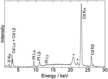 | ||
| Fig. 1 X-ray fluorescence spectrum of Pt/CdS-NR. Peaks marked with asterisks originate from the X-ray source as Ag Kα,β radiation. | ||
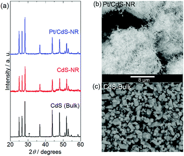 | ||
| Fig. 2 (a) PXRD patterns of Pt/CdS-NR, CdS-NR sample, and CdS bulk reference. The peak marked with an asterisk of CdS bulk is assigned to CdO on the CdS surface.49 SEM images of (b) Pt/CdS-NR and (c) CdS bulk. The scale bar (8 μm) is shown between panels (b) and (c). | ||
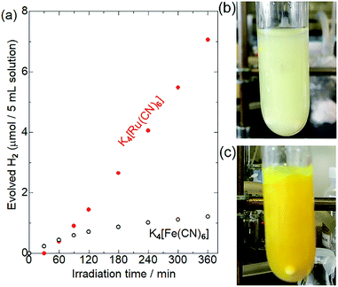
Photocatalytic H2 evolution reaction with [M(CN)6]4−
Fig. 3 shows the results of photocatalytic hydrogen evolution reactions using K4[M(CN)6] (M = Fe or Ru) as the electron donor. As has been widely reported,30–35 Pt/CdS-NR produced ∼1.2 μmol of H2 after light irradiation for 6 h in the presence of K4[Fe(CN)6]. A slight decrease of the photocatalytic activity observed after 180 min of irradiation might be due to the photoinduced ligand exchange reaction of the one-electron oxidized [Fe(CN)6]3− anions as suggested by Abe et al.35 Surprisingly, approximately six-fold more H2 (7.1 μmol) evolved in the presence of K4[Ru(CN)6] after a 30 min induction period. After irradiation for 24 h, the amount of H2 evolved in the presence of [Ru(CN)6]4− was 20.8 μmol (Fig. S2†). This amount of H2 is significantly larger than the molar amount of CdS-NR (∼14 μmol), suggesting that [Ru(CN)6]4− serves as an electron donor for the H2 evolution reaction, even if electron-donating S2− anions were generated by the photocorrosion of CdS-NR. Notably, a larger amount of H2 evolved in the presence of [Ru(CN)6]4− than in the presence of [Fe(CN)6]4− despite the more positive M(III)/M(II) redox potential of [Ru(CN)6]4− (+0.89 V vs. NHE) than [Fe(CN)6]4− (+0.36 V vs. NHE). Note that a negligible amount of H2 was generated in the absence of [M(CN)6]4− (M = Fe or Ru) in acetate buffer solution (Fig. S3†), indicating that the acetate anion did not act as the electron source for the H2 evolution reaction.To elucidate the differences between these two [M(CN)6]4−, we first examined their adsorption behaviours on the CdS-NR surface based on their zeta potentials. The zeta potentials in aqueous solutions of [Fe(CN)6]4− and [Ru(CN)6]4− were comparable at approximately −30 mV, which was significantly shifted to the negative when compared to that in the absence of [M(CN)6]4− (Table S1†). Thus, as expected from their similar molecular structures, the CdS-NR surface was negatively charged following the adsorption of [M(CN)6]4− anions, and the difference in the extent of adsorption between these two [M(CN)6]4− should be negligible. However, a large colour difference of the dispersed solutions is observed after a 6 h photocatalytic H2 evolution reaction; a large amount of white precipitate formed in the reaction solution with [Ru(CN)6]4− while only a yellow suspension of Pt/CdS-NR was observed for the solution with [Fe(CN)6]4− as shown in Fig. 3(b) and (c).
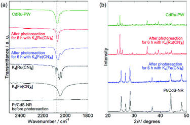
To identify the white precipitate formed in the reaction solution with [Ru(CN)6]4−, PXRD and IR spectral measurements of the precipitates isolated from the reaction solutions by centrifugation were conducted. Fig. 4(a) shows the IR spectra of the precipitates. As reported in the literature, K4[Fe(CN)6] and K4[Ru(CN)6] exhibit stretching vibrations of the cyanido ligand ν(C![[triple bond, length as m-dash]](https://www.rsc.org/images/entities/char_e002.gif) N) at 2043 cm−1 and 2054 cm−1, respectively. Although no peak was observed in this region for Pt/CdS-NR prior to the photocatalytic H2 evolution reaction, a peak similar to that observed for K4[M(CN)6] was observed for the precipitates isolated from the reaction solution with K4[M(CN)6] (M = Fe or Ru) after 6 h of light irradiation. Notably, the peak position attributable to the ν(C
N) at 2043 cm−1 and 2054 cm−1, respectively. Although no peak was observed in this region for Pt/CdS-NR prior to the photocatalytic H2 evolution reaction, a peak similar to that observed for K4[M(CN)6] was observed for the precipitates isolated from the reaction solution with K4[M(CN)6] (M = Fe or Ru) after 6 h of light irradiation. Notably, the peak position attributable to the ν(C![[triple bond, length as m-dash]](https://www.rsc.org/images/entities/char_e002.gif) N) mode shifted to higher wavelength (by approximately 20 cm−1) relative to that of K4[M(CN)6]. It was previously reported that the Prussian white analogue K2[CdFe(CN)6] (hereafter CdFe-PW) was in situ generated on the CdS surface in the photocatalytic H2 evolution reaction in the presence of [Fe(CN)6]4− because of the partial photocorrosion of CdS, which provides Cd2+ ions to form CdFe-PW.35 The peak position of the ν(C
N) mode shifted to higher wavelength (by approximately 20 cm−1) relative to that of K4[M(CN)6]. It was previously reported that the Prussian white analogue K2[CdFe(CN)6] (hereafter CdFe-PW) was in situ generated on the CdS surface in the photocatalytic H2 evolution reaction in the presence of [Fe(CN)6]4− because of the partial photocorrosion of CdS, which provides Cd2+ ions to form CdFe-PW.35 The peak position of the ν(C![[triple bond, length as m-dash]](https://www.rsc.org/images/entities/char_e002.gif) N) mode is known to shift to higher wavelength on bridging two metal centers.50 Thus, the higher-wavelength-shifted ν(C
N) mode is known to shift to higher wavelength on bridging two metal centers.50 Thus, the higher-wavelength-shifted ν(C![[triple bond, length as m-dash]](https://www.rsc.org/images/entities/char_e002.gif) N) vibrations observed for the precipitates clearly suggest the in situ formation of Prussian white analogues (CdFe-PW or CdRu-PW) during the photocatalytic H2 evolution reaction. In fact, the Prussian white analogue CdRu-PW prepared by a simple solution reaction (see the Preparation of K2[CdRu(CN)6]) exhibited a ν(C
N) vibrations observed for the precipitates clearly suggest the in situ formation of Prussian white analogues (CdFe-PW or CdRu-PW) during the photocatalytic H2 evolution reaction. In fact, the Prussian white analogue CdRu-PW prepared by a simple solution reaction (see the Preparation of K2[CdRu(CN)6]) exhibited a ν(C![[triple bond, length as m-dash]](https://www.rsc.org/images/entities/char_e002.gif) N) vibration at a position (2072 cm−1) almost identical to that observed for the precipitates.
N) vibration at a position (2072 cm−1) almost identical to that observed for the precipitates.
Fig. 4(b) shows the PXRD patterns of the precipitates isolated from the reaction solutions after 6 h of irradiation. The PXRD pattern of the precipitate obtained from the reaction solution with K4[Fe(CN)6] was almost identical to that of the original Pt/CdS-NR. In contrast, the pattern for the precipitate isolated from the reaction solution with K4[Ru(CN)6] was completely different from that of the original Pt/CdS-NR and qualitatively agreed with that of CdRu-PW. These contrasting results clearly indicate a significant difference in the production of the Prussian white complexes involving these two [M(CN)6]4−; a relatively large amount of CdRu-PW was produced as the by-product during the photocatalytic H2 evolution reaction while only a trace amount of CdFe-PW was produced on the CdS-NR surface. In fact, many block-shaped microcrystals were observed for the precipitate in the SEM image, and X-ray fluorescence derived from K, Cd, and Ru was clearly observed in the EDX spectra (Fig. S4 and S5†). Furthermore, the number of block-shaped microcrystals of CdRu-PW observed in the SEM image and the peak intensities of the Ru Lα and Lβ radiations in the EDX spectra were increased by increasing the light irradiation time.
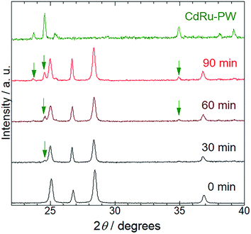
To characterize the production mechanism of CdRu-PW during the photocatalytic hydrogen evolution reaction in the presence of K4[Ru(CN)6], PXRD analysis was conducted for the samples isolated at 30 min irradiation intervals. As shown in Fig. 5, diffraction peaks originating from Pt/CdS-NR were observed for all the samples used in these measurements. Notably, diffraction peaks assignable to CdRu-PW (indicated by green arrows in Fig. 5) gradually appeared as the irradiation time increased, indicating the growth of CdRu-PW microcrystals during the photocatalytic H2 evolution reaction. Actually, the SEM images of these samples clearly indicate that the number of block crystals of CdRu-PW increased by increasing the light irradiation time (Fig. S4(a) to S4(e)†). It should be noted that the induction period (∼30 min) of the photocatalytic H2 evolution reaction in the presence of K4[Ru(CN)6] almost corresponds with the time taken for the production of CdRu-PW, and the amount of CdRu-PW produced seems to increase as the irradiation time is increased. Because elucidating the actual electron source for H2 evolution under these conditions is crucial, we examined the change of the sample mass after the photocatalytic H2 evolution by isolating the insoluble precipitates via centrifugation to estimate the amount of CdRu-PW produced, as Cd2+ cations generated from the photocorrosion of CdS-NR are necessary to produce CdRu-PW. Our preliminary experiments based on UV-Vis spectroscopy roughly estimated the solubility product of CdFe-PW and CdRu-PW (KSP = 7.8 × 10⁻¹⁰ and 1.7 × 10⁻¹² (mol2 L−2), respectively) to be comparable to that of the widely known insoluble AgCl (1.7 × 10⁻¹⁰ mol2 L−2), suggesting that dissolution of these Prussian white analogues in water was negligible in these experiments. The original sample mass before the photocatalytic H2 evolution reaction was 2.00 mg (corresponding to the mass of Pt/CdS-NR only), because the K4[Ru(CN)6] mediator was completely dissolved in the acetate buffer solution. Interestingly, the sample masses in the presence of K4[Ru(CN)6] after 6 and 21 h of irradiation increased to 3.98 and 4.50 mg, respectively, suggesting the production of CdRu-PW. These values are significantly larger than that after 6 h of irradiation in the K4[Fe(CN)6] solution (2.52 mg). In the photocorrosion process of CdS-NR, not only Cd2+ cations but also the same molar amount of S2− anions would be produced. The S2− anion is a well-known sacrificial donor to donate two electrons to form H2,46–48 and the potential for the photocorrosion of CdS to donate two electrons was reported to be 0.32 V vs. NHE.51 Thus, to estimate the amount of CdRu-PW produced, we assumed that the following photochemical reaction occurs:
| CdS + aK4[Ru(CN)6] + 2aH+ → (1 − a) CdS + a{K2[CdRu(CN)6]} + 2aK+ + aS + aH2 | (1) |
| Redox mediator | Irradiation time (h) | Sample mass (mg) | Photo-corroded CdS-NR (mol%)a | CdM-PW produced (μmol)a | H2 evolved (μmol)b |
|---|---|---|---|---|---|
| a Estimated by eqn (1). b Estimated by GC analysis. | |||||
| [Ru(CN)6]4− | 0 | 2.00 | 0 | — | — |
| [Ru(CN)6]4− | 6 | 3.98 | 42.8 | 5.92 | 7.5 |
| [Ru(CN)6]4− | 21 | 4.50 | 54.1 | 7.47 | 20.8 |
| [Fe(CN)6]4− | 6 | 2.52 | 12.0 | 1.11 | 1.2 |
Mechanistic aspects of photocatalytic H2 evolution with [M(CN)6]4−
As discussed in the “Photocatalytic H2 evolution reaction with [M(CN)6]4−” section, replacing the widely used electron mediator [Fe(CN)6]4− by its Ru(II) analogue [Ru(CN)6]4− greatly affects the photocatalytic H2 evolution reaction. In this section, we discuss the mechanistic differences of this reaction for these two hexacyanidometallates. Scheme 1 shows a schematic energy diagram for the photocatalytic H2 evolution reaction using a Pt/CdS-NR photocatalyst and a K4[M(CN)6] (M = Fe or Ru) mediator. In the reaction with [Fe(CN)6]4−, as reported previously,35 a trace amount of CdFe-PW is initially generated on the Pt/CdS-NR surface and functions as an effective mediator to transfer the hole from CdS-NR to [Fe(CN)6]4−. This is supported by the results showing a small change of the sample mass after the reaction (∼0.5 mg) and the formation of one-electron oxidized [FeIII(CN)6]3− in the UV-Vis spectrum (Fig. S7†). By comparison, the M(III)/M(II) redox potential of [Ru(CN)6]4− is more positive than that of [Fe(CN)6]4− (Scheme 1). In this case, the one-electron oxidized [Ru(CN)6]3− species generated by accepting the hole from the photoexcited Pt/CdS-NR rapidly recombines with the excited electron to revert to its initial state, or it oxidizes the S2− anion on the CdS-NR surface to generate Cd2+ cations. Given that a two-electron oxidation is required for the conversion of S2− to S0, the observed induction period of ∼30 min would be caused by the recombination process between the one-electron oxidized [RuIII(CN)6]3− species and the excited electron in Pt/CdS-NR. As a result, the photocatalytic H2 evolution reaction in the initial several hours is mainly driven by the consumption of S2− anions as the electron source, with a large amount of CdRu-PW (∼5.9 μmol) being produced as the by-product of photocorrosion. This photocorrosion process was observed as a decrease of the band-gap transition intensity in the UV-Vis diffuse reflectance spectra of Pt/CdS-NR isolated by centrifugation from the reaction solution (Fig. S8†). As the CdS-NR surface becomes covered by CdRu-PW; however, the electron source for H2 evolution is changed from S2− to [Ru(CN)6]4−, because the CdRu-PW deposited on the CdS-NR surface not only suppresses the photocorrosion of CdS-NR as a surface passivating layer but also improves the hole transfer efficiency from the photoexcited CdS-NR to [Ru(CN)6]4− in solution by its reversible Ru(III)/Ru(II) redox mediating/accumulating ability. Unfortunately, however, the surface passivation effect due to the in situ generated CdRu-PW in our present reaction is not sufficient to suppress the photocorrosion of CdS-NR, resulting in the photocorrosion of over 50% of CdS-NR after 21 h of irradiation even in the presence of a 3-times higher concentration of K2[Ru(CN)6] (see Fig. S9†).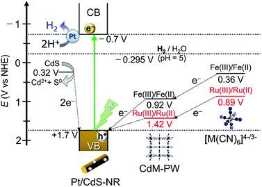 | ||
| Scheme 1 Schematic energy diagram for the photocatalytic H2 evolution reaction driven by Pt/CdS-NR in the presence of K4[M(CN)6] (M = Fe or Ru) redox mediators. | ||
Conclusions
In this work, we have investigated the photocatalytic H2 evolution reaction driven by Pt-co-catalyst loaded nanorod-shaped CdS (Pt/CdS-NR) by using two different redox mediators, the widely used hexacyanidoferrate [Fe(CN)6]4− and its Ru(II) analogue [Ru(CN)6]4−. Interestingly, more H2 evolved in the presence of [Ru(CN)6]4− than in the presence of [Fe(CN)6]4− despite the more positive Ru(III)/Ru(II) redox potential than the Fe(III)/Fe(II) couple. PXRD and IR spectral experiments clearly indicate that only a trace amount of CdFe-PW was formed on the surface of Pt/CdS-NR in the photocatalytic H2 evolution reaction in the presence of [Fe(CN)6]4−, whereas the Ru(II) analogue CdRu-PW was increasingly formed when a K4[Ru(CN)6] aqueous solution was used as the electron source. Our careful analysis of the amount of CdRu-PW produced during the photocatalytic H2 evolution reaction suggests that the electron source for H2 evolution was gradually changed from S2− anions generated by the photocorrosion of CdS-NR to [Ru(CN)6]4−, due to the hole mediating ability of the CdRu-PW deposited on the CdS-NR surface. Since CdRu-PW is colourless and the Ru(III)/Ru(II) redox potential is more positive than the potential of water oxidation, it could be a promising hole mediating material for solar water splitting that would not suppress the light absorption of photocatalysts/photosensitizers. Further studies to suppress the photocorrosion of CdS-NR viz. formation of a thin film composed of Prussian white analogues are now in progress.Conflicts of interest
There are no conflicts to declare.Acknowledgements
The authors thank Dr Y. Shibata (Bruker, Japan) for the valuable support with the XRF measurements. This study was supported by the Shimadzu Science Foundation, Shorai Science and Technology Foundation, Murata Science Foundation, Grants-in-Aid for Scientific Research (C)(26410063), Artificial Photosynthesis (area No. 2406, No. 15H00858), and Soft Crystals (area No. 2903, No. JP17H06367) from MEXT, Japan.References
- A. Fujishima and K. Honda, Nature, 1972, 238, 37–38 CrossRef PubMed.
- M. D. Hernandez-Alonso, F. Fresno, S. Suareza and J. M. Coronado, Energy Environ. Sci., 2009, 2, 1231–1257 RSC.
- A. Kudo and Y. Miseki, Chem. Soc. Rev., 2009, 38, 253–278 RSC.
- X. Chem, S. Shen, L. Guo and S. S. Mao, Chem. Rev., 2010, 110, 6503–6570 CrossRef PubMed.
- K. Maeda, ACS Catal., 2013, 3, 1486–1503 CrossRef.
- J. Yang, D. Wang, H. Han and C. Li, Acc. Chem. Res., 2013, 46, 1900–1909 CrossRef PubMed.
- K. Maeda, T. Takata, M. Hara, N. Saito, Y. Inoue, H. Kobayashi and K. Domen, J. Am. Chem. Soc., 2005, 127, 8286–8287 CrossRef PubMed.
- Y. Lee, H. Terashima, Y. Shimodaira, K. Teramura, M. Hara, H. Kobayashi, K. Domen and M. Yashima, J. Phys. Chem. C, 2007, 111, 1042–1048 CrossRef.
- K. Maeda, M. Higashi, D. Lu, R. Abe and K. Domen, J. Am. Chem. Soc., 2010, 132, 5858–5868 CrossRef PubMed.
- R. Abe, M. Higashi and K. Domen, J. Am. Chem. Soc., 2010, 132, 11828–11829 CrossRef PubMed.
- K. Maeda, M. Higashi, B. Siritanaratkul, R. Abe and K. Domen, J. Am. Chem. Soc., 2011, 133, 12334–12337 CrossRef PubMed.
- C. Pan, T. Takata, M. Nakabayashi, T. Matsumoto, N. Shibata, Y. Ikuhara and K. Domen, Angew. Chem., Int. Ed., 2015, 54, 2955–2959 CrossRef PubMed.
- Y. Nosaka, K. Yamaguchi, A. Kuwabara, H. Miyama, R. Baba and A. Fujishima, J. Photochem. Photobiol., A, 1992, 64, 375–382 CrossRef.
- J.-F. Reber and M. Rusek, J. Phys. Chem., 1986, 90, 824–834 CrossRef.
- D. Jing and L. Guo, J. Phys. Chem. B, 2006, 110, 11139–11145 CrossRef PubMed.
- X. Zong, H. Yan, G. Wu, G. Ma, F. Wen, L. Wang and C. Li, J. Am. Chem. Soc., 2008, 130, 7176–7177 CrossRef PubMed.
- N. Bao, L. Shen, T. Takata and K. Domen, Chem. Mater., 2008, 20, 110–117 CrossRef.
- H. Yan, J. Yang, G. Ma, G. Wu, X. Zong, Z. Lei, J. Shi and C. Li, J. Catal., 2009, 266, 165–168 CrossRef.
- C. Xing, Y. Zhang, W. Yan and L. Guo, Int. J. Hydrogen Energy, 2006, 31, 2018–2024 CrossRef.
- X. Wang, G. Liu, Z.-G. Chen, F. Li, L. Wang, G. Q. Lu and H.-M. Cheng, Chem. Commun., 2009, 23, 3452–3454 RSC.
- Q. Li, B. Guo, J. Yu, J. Ran, B. Zhang, H. Yan and J. R. Gong, J. Am. Chem. Soc., 2011, 133, 10878–10884 CrossRef PubMed.
- J. Zhang, J. Yu, M. Jaroniec and J. R. Gong, Nano Lett., 2012, 12, 4584–4589 CrossRef PubMed.
- Z. Han, F. Qiu, R. Eisenberg, P. L. Holland and T. D. Krauss, Science, 2012, 338, 1321–1324 CrossRef PubMed.
- K. Sawaguchi-Sato, A. Kobayashi, M. Yoshida and M. Kato, J. Photochem. Photobiol., A, 2017, 335, 182–189 CrossRef.
- H. Kunioku, M. Higashi, O. Tomita, M. Yabuuchi, D. Kato, H. Fujito, H. Kageyama and R. Abe, J. Mater. Chem. A, 2018, 6, 3100–3107 RSC.
- H. Kunioku, A. Nakada, M. Higashi, O. Tomita, H. Kageyama and R. Abe, Sustainable Energy Fuels, 2018, 2, 1474–1480 RSC.
- R. Williams, J. Chem. Phys., 1960, 32, 1505–1507 CrossRef.
- D. J. Fermín, E. A. Ponomarev and L. M. Peter, J. Electroanal. Chem., 1999, 473, 192–203 CrossRef.
- T. Inoue, T. Watanabe, A. Fujishima, K. Honda and K. Kohayakawa, J. Electrochem. Soc., 1977, 124, 719–722 CrossRef.
- H.-D. Rubin, B. D. Humphrey and A. B. Bocarsly, Nature, 1984, 308, 339 CrossRef.
- H.-D. Rubin, D. J. Arent, B. D. Humphrey and A. B. Bocarsly, J. Electrochem. Soc., 1987, 134, 93–101 CrossRef.
- Y. Tachibana, K. Umekita, Y. Otsuka and S. Kuwabata, J. Phys. D: Appl. Phys., 2008, 41, 102002 CrossRef.
- R. M. Evangelista, S. Makuta, S. Yonezu, J. Andrews and Y. Tachibana, ACS Appl. Mater. Interfaces, 2016, 8, 13957–13965 CrossRef PubMed.
- Z. Li, W. Wang, C. Ding, Z. Wang, S. Liao and C. Li, Energy Environ. Sci., 2017, 10, 765–771 RSC.
- T. Shirakawa, M. Higashi, O. Tomita and R. Abe, Sustainable Energy Fuels, 2017, 1, 1065–1073 RSC.
- W. Wang, J. Chen, C. Li and W. Tian, Nat. Commun., 2014, 5, 4647 CrossRef PubMed.
- L. J. Zhang, S. Li, B. K. Liu, D. J. Wang and T. F. Xie, ACS Catal., 2014, 4, 3724–3734 CrossRef.
- T. Kato, Y. Hakari, S. Ikeda, Q. Jia, A. Iwase and A. Kudo, J. Phys. Chem. Lett., 2015, 6, 1042–1047 CrossRef PubMed.
- L. E. Brus, J. Chem. Phys., 1984, 80, 4403–4409 CrossRef.
- K. Itaya, T. Ataka and S. Toshima, J. Am. Chem. Soc., 1982, 104, 4767–4772 CrossRef.
- K. Itaya, I. Uchida and V. D. Neff, Acc. Chem. Res., 1986, 19, 162–168 CrossRef.
- F. Scholz and A. Dostal, Angew. Chem., Int. Ed., 1995, 34, 2685–2687 CrossRef.
- A. A. Karyakin, Electroanalysis, 2001, 13, 813–819 CrossRef.
- J. N. Behera, D. M. D'Alessandro, N. Soheilnia and J. R. Long, Chem. Mater., 2009, 21, 1922–1926 CrossRef.
- E. Reguera, A. Gomez, J. Balmaseda, G. Contreras and A. Escamilla, Struct. Chem., 2001, 12, 59–66 CrossRef.
- J. S. Jang, U. A. Joshi and J. S. Lee, J. Phys. Chem. C, 2007, 111, 13280–13287 CrossRef.
- J. Jin, J. Yu, G. Liu and K. Wong, J. Mater. Chem. A, 2013, 1, 10927–10934 RSC.
- Z. Sun, H. Zheng, J. Li and P. Du, Energy Environ. Sci., 2015, 8, 2668–2677 RSC.
- Y. Fan, M. Deng, G. Chen, Q. Zhang, Y. Luo, D. Li and Q. Meng, J. Alloys Compd., 2011, 509, 1477–1481 CrossRef.
- K. Nakamoto, Infrared and Raman Spectra of Inorganic and Coordination Compounds, Part B, Wiley, 6th edn, 2008, pp. 110–117 Search PubMed.
- A. J. Bard and M. S. Wrighton, J. Electrochem. Soc., 1977, 124, 1706–1710 CrossRef.
Footnote |
| † Electronic supplementary information (ESI) available: TEM, SEM, and EDX spectra of Pt/CdS-NR, results of the long-duration photocatalytic H2 evolution reaction, CV of the CdRu-PW-modified ITO electrode, UV-Vis spectra of the reaction solution and in situ generated precipitate, and details of estimating the CdRu-PW mass. See DOI: 10.1039/c8se00201k |
| This journal is © The Royal Society of Chemistry 2018 |

