
A low cost ultra-microporous carbon scaffold with confined chain-like sulfur molecules as a superior cathode for lithium–sulfur batteries†
Junkai
Han
a,
Yu
Li
abc,
Shuangwen
Li
a,
Peng
Long
a,
Chen
Cao
a,
Yu
Cao
a,
Weizhe
Wang
a,
Yiyu
Feng
abc and
Wei
Feng
 *abcd
*abcd
aSchool of Materials Science and Engineering, Tianjin University, PR China. E-mail: weifeng@tju.edu.cn
bKey Laboratory of Advanced Ceramics and Machining Technology, Ministry of Education, PR China
cTianjin Key Laboratory of Composite and Functional Materials, Tianjin 300072, PR China
dCollaborative Innovation Center of Chemical Science and Engineering, Tianjin, PR China
First published on 22nd May 2018
Abstract
Lithium–sulfur (Li–S) batteries with high energy density are one of the most promising energy storage systems. However, the shuttle effect due to the transition between ring-like S8 molecules and high order polysulfides (Li2Sn, 4 < n ≤ 8) hinders their practical application. Utilizing chain-like S2–4 molecules is considered to be an effective strategy to avoid this unfavorable process; however, the preparation of a carbon scaffold with ultra-micropores to constrain S2–4 molecules is challenging. In this study, a carbon scaffold derived from macadamia nut shell (MNS) with predominant ultra-micropores of sizes less than 0.6 nm is obtained by a simple KOH etching reaction followed by a calcination process. The calcined MNS (c-MNS) exhibits a high specific surface area (1687 m2 g−1), large pore volume (0.57 cm3 g−1), and large number of ultra-micropores (<0.6 nm) that account for 80% of the total specific surface area and 61.4% of the total pore volume. Then, a series of c-MNS/S composites are fabricated through a melt diffusion strategy. The electrochemical performances of c-MNS/S composites used as the cathodes of Li–S batteries are evaluated. The composites deliver a maximum reversible capacity of 1254 mA h g−1 at 0.1C rate (1C = 1675 mA g−1), with a capacity retention of 80% after 100 cycles, and can operate steadily up to 2C rate with a reversible capacity of 540 mA h g−1.
Introduction
Lithium–sulfur (Li–S) batteries with high energy density (2600 W h kg−1) have been considered as one of the most prominent candidates for next generation energy storage power systems to satisfy the increasing energy consumption of portable electronic devices, besides several advantages of sulfur cathodes, such as low cost, abundance, environmental-friendliness, etc.1 This high energy density is attributed to the two electron conversion reactions between sulfur and lithium, unlike conventional intercalation compound cathodes for commercial Li-ion batteries which can utilize only one or less than one electron per transition metal ion. However, there are several problems of the sulfur cathode that impede the commercialization Li–S batteries drastically, including the extremely low electrical conductivity of sulfur (5 × 10⁻³⁰ S cm−1) and their discharge products (Li2S and Li2S2), the large volumetric change of sulfur during the lithiation/delithiation process (∼80%), and the rapid deterioration of capacity caused by the solubility of high order polysulfides in the electrolyte.2,3 To address these problems, many approaches have been proposed to optimize the components and architectures of sulfur cathodes, and the distribution of sulfur in appropriate hosts to confine polysulfides through physical/chemical interactions is the most widely applied method. To date, various sulfur hosts, including carbonaceous materials, polymers, metal oxides, and metal–organic frameworks, have been developed.4–7Among these hosts, nanostructured carbons including hollow carbon spheres, carbon fibers, carbon nanotubes, graphene, and porous carbons, have received predominant attention because of their advantages such as light weight, high electrical conductivity, and structural maneuverability.8 Nanostructured carbons with a hierarchical porous structure and appropriate pore size distribution are deemed to be appropriate hosts of sulfur owing to the effective suppression of the dissolution of polysulfides, which significantly improves the cycling stability of Li–S batteries compared to that of the pure sulfur cathode. This was first reported by Nazar et al., who selected highly ordered mesoporous carbon (CMK-3) as the sulfur host to realize the high electrical conductivity of the composite and physical confinement of polysulfides by capillary forces.9 Although this strategy significantly improved the cycling stability of Li–S batteries, it is still unsatisfactory for practical applications because the conventional ring-like S8 molecules accommodated in the large number of mesopores in CMK-3, with an average size of 3.33 nm, were easily accessed by the electrolyte. As a result, dissolution of discharge products in the form of high order polysulfides is still inevitable.
Recently, it has been proposed that using small chain-like sulfur allotropes (S2–4) with a length of ∼0.6 nm is one possible strategy to resolve the capacity fading of Li–S batteries because the discharge products of chain-like S2–4 molecules are low order polysulfides (Li2Sn, 2 ≤ n ≤ 4) that are insoluble in conventional electrolytes of Li–S batteries, resulting in remarkably enhanced sulfur utilization and capacity retention. However, chain-like S2–4 molecules are thermodynamically unstable, and they spontaneously convert to ring-like S8 molecules. The accommodation of chain-like S2–4 molecules into the ultra-micropores of materials with pore sizes less than 0.6 nm can sustain their chain-like molecular form owing to space limitations.10 Besides, the chain-like S2–4 molecules in the ultra-micropores can't be accessed by the electrolyte molecules, thus making this carbon/sulfur composite compatible with the commonly used carbonate-based electrolyte other than the ether-based electrolyte with LiNO3 as an additive.11 The breakthrough work of ultra-microporous carbon/sulfur composites was published by Gao et al.12 in 2010. In this work, ultra-microporous carbon spheres with an average pore size of ∼0.7 nm were synthesized using sucrose and sulfuric acid as the raw materials, and then, chain-like S2–4 molecules produced by heating sublimed sulfur at 149 °C for 6 h in a sealed vessel were successfully encapsulated into these ultra-micropores. The obtained composite exhibited a large reversible capacity of ∼650 mA h g−1 after 500 cycles at a current density of 400 mA g−1. Unfortunately, the remaining ring-like S8 molecules in the existent mesopores inevitably deteriorated the overall electrochemical performance. Therefore, there is a critical demand for developing ultra-microporous carbon hosts with a narrow pore size distribution. In view of this, Guo et al. designed a carbon host with a dominant pore size of 0.5 nm to accommodate chain-like S2–4 molecules. This was achieved through a tedious process by coating an ultra-microporous carbon layer produced by the reaction between D-glucose and sodium dodecyl sulfate onto multi-walled carbon nanotubes. The corresponding composite exhibited an impressive cycling capacity of 1149 mA h g−1 after 200 cycles at 0.1C.10 To date, ultra-microporous carbons with a narrow pore size distribution have also been prepared by carbonizing alkali-complexes, organic–organic assemblies, graphene templates, etc.13–15
However, the synthesis of carbon hosts with homogeneous ultra-micropores usually incurs relatively high costs and involves complicated preparation procedures that present difficulties in scaling up. Herein, a new kind of carbonaceous host material was prepared by the calcination of macadamia nut shell (c-MNS), a bio-waste material, with the aid of a KOH etching method. The resulting material exhibited a high proportion of ultra-micropores, up to 0.35 cm3 g−1 and a narrow size distribution centered at 0.52 nm. Through a two-step melt-diffusion strategy, the scission of ring-like S8 molecules was accomplished, and the formed chain-like S2–4 molecules were accommodated into the ultra-micropores of c-MNS. Upon optimizing the content of sulfur, the obtained c-MNS/S composites used as the cathodes of Li–S batteries delivered a maximum initial reversible capacity of 1254 mA h g−1 at 0.1C rate (1C = 1675 mA g−1), with a capacity retention of 80% after 100 cycles at 0.1C, and exhibited an excellent rate capability with a capacity retention of 540 mA h g−1 at 2C rate.
Experimental
Materials
Lithium hexafluorophosphate (LiPF6), ethylene carbonate (EC), and diethyl carbonate (DEC) were purchased from China J&K Tech Ltd. N-Methyl-2-pyrrolidone (NMP) were acquired from Sigma-Aldrich. PVDF, KOH, HCl, and Super-P carbon were obtained from Tianjin GuangFu Chemical Company. All reagents were used as received.Preparation of c-MNS
A MNS was first repeatedly washed with deionized water and alcohol and dried overnight at 80 °C. Then, the resulting material was well ground with a pulverizer (CF-10A, Wenling Chuangli Instrument Company). A certain amount of the dried powder of the nut shell was dispersed in a saturated solution of KOH in water at a mass ratio of 1![[thin space (1/6-em)]](https://www.rsc.org/images/entities/char_2009.gif) :2 in a stainless crucible. The resulting homogeneous slurry was dried overnight at 120 °C. Subsequently, the samples were heated to 800 °C (at a rate of 5 °C min−1) under an Ar flow and calcined at 800 °C for 1 h before cooling naturally under the protection of Ar. The final products were washed sequentially with 0.1 M HCl, hot water, and finally cold water to remove residual impurities until the pH of the filtrate was neutral. Further, the sample was dried overnight at 80 °C, and the product obtained thus was labeled c-MNS.
:2 in a stainless crucible. The resulting homogeneous slurry was dried overnight at 120 °C. Subsequently, the samples were heated to 800 °C (at a rate of 5 °C min−1) under an Ar flow and calcined at 800 °C for 1 h before cooling naturally under the protection of Ar. The final products were washed sequentially with 0.1 M HCl, hot water, and finally cold water to remove residual impurities until the pH of the filtrate was neutral. Further, the sample was dried overnight at 80 °C, and the product obtained thus was labeled c-MNS.
Preparation of c-MNS/S composites
The c-MNS/S composites were prepared following a melt diffusion strategy. Sublimed sulfur powder (Aldrich, purity >99.99%) and c-MNS were mixed thoroughly by ball-milling for 1 h at mass ratios of 1:3, 2:3, and 3:2, respectively. The resultant black mixtures were transferred into small beakers, and the beakers were sealed in a N2-filled Teflon container for further two-step heat treatment. After cooling to room temperature, the c-MNS/S composites were collected.
Structural characterization
The microstructure and morphology of the prepared materials were investigated with a field emission transmission electron microscope (FETEM, JEOL JEM-2100F) and field emission scanning electron microscope (FESEM, Hitachi S-4800) equipped with an energy dispersive X-ray spectrometer (EDS); the latter was used to carry out EDS analysis and obtain elemental maps. X-ray diffraction (XRD) patterns were obtained using a diffractometer (Bruker D8 Advance with Cu Kα radiation). FTIR spectra were recorded on a Bruker Tensor 27 spectrometer with a disc of KBr containing the sample. Thermogravimetric analysis (TGA) was carried out on a thermogravimetric analyzer (Q2000, TA. Inst., USA). The samples were heated from room temperature to 800 °C at a rate of 5 °C min−1 in an aluminum crucible under nitrogen. X-ray photoelectron spectroscopy (XPS) was performed on a Perkin Elmer Phi 3056 spectrometer with an Al anode source operated at 15 kV and an applied power of 350 W. The specific surface area and pore volume of the samples were determined using N2 adsorption and desorption isotherms obtained at 77 K on an Autosorb-iQ2-MP (Quantachrome, USA) based on the DFT method.Electrochemical measurements
The cathodes were prepared by coating an NMP-based slurry containing 80 wt% c-MNS/S composite, 10 wt% PVDF, and 10 wt% super-P carbon onto carbon-coated Al foil with a doctor blade and dried overnight at 60 °C. After drying, the Al foil was cut (Φ = 12 mm) to fabricate the sulfur electrode. The sulfur loading mass on the Al foil was determined to be about 1 mg cm−2. The 2032-type coin cells were assembled in an argon-filled glove box (Mikrouna Co., Advanced 2440/750) with lithium metal as the counter electrode and Celgard 2400 as the separator. The electrolyte was 1 M LiPF6 dissolved in a mixture of EC–DEC (1:1 by volume). The amount of added electrolyte per cell was about 20 μL. The galvanostatic discharge–charge tests were conducted within a voltage window of 1.0–3.0 V (vs. Li/Li+) using a Land 2001A cell system (Wuhan, China) at 25 °C. The specific capacity of the cell used in this study was calculated based on the sulfur mass in the cathode. Cyclic voltammetry (CV) was performed over the potential range of 1.0–3.0 V (vs. Li/Li+) at a scanning rate of 0.1 mV s−1 using a CHI660D electrochemical workstation. Electrochemical impedance spectroscopy (EIS) was performed over the frequency range of 1 MHz to 10 mHz using a VersaSTAT 3 electrochemical workstation (Princeton Applied Research, USA) at a voltage amplitude of 5 mV.
Results and discussion
Scheme 1 illustrates the typical synthetic process of c-MNS/S composites. Waste MNSs were first washed repeatedly with deionized H2O and ethanol and then pulverized into a powder. Afterwards, the powder was ultrasonically dispersed in a saturated KOH solution at a mass ratio of MNS:KOH = 2:1. Then, the dispersion was vaporized overnight at 120 °C for the complete impregnation of MNS with KOH.16 After calcining the mixed powder of MNS and KOH at 800 °C for 1 h under Ar protection, a black fluffy powder was obtained, which was further washed with 1 M HCl to remove the residual KOH and then rinsed thoroughly with de-ionized water to obtain the c-MNS powder. Sublimed sulfur and c-MNS were thoroughly mixed at S:c-MNS mass ratios of 1:3, 2:3, and 3:2 by ball-milling for 1 h to obtain a black mixture, each of which was then transferred into a small beaker. Subsequently, the beaker was sealed in a N2-filled Teflon container for further heat treatment. Initially, the temperature was slowly increased up to the melting point of sulfur at 115 °C at a rate of 1 °C min−1 and held at this temperature for 8 h. This is followed by a sequential heating process with a slow rate of 0.5 °C min−1 until the temperature reached 155 °C, where liquid sulfur has the lowest viscosity. An additional 24 h of the temperature preservation process was applied to ensure the complete scission of ring-like S8 molecules and efficient impregnation of the scissored sulfur molecules into c-MNS.
 | ||
| Scheme 1 The preparation process of c-MNS/S composites. | ||
After cooling the mixture to room temperature, the c-MNS/S composites were collected and labeled c-MNS/S25, c-MNS/S40, and c-MNS/S60, respectively, according to the mass percentage of sulfur in the mixed powder of sulfur and c-MNS.
Since the pores of c-MNS act as the reservoirs and micro-reactors of sulfur, the porous structure of c-MNS was first characterized through N2 adsorption–desorption measurements. As shown in Fig. 1a, c-MNS exhibits an isotherm with a steep increase at low relative pressures and gradual increase at the rest of the relative pressures with no apparent hysteresis, indicating a characteristic type-I behavior.17 The c-MNS has a large nitrogen adsorption volume when the P/P0 value is below 0.1, indicating the existence of abundant micropores.18 The gentle adsorption slope in the range of P/P0 from 0.1 to 0.9 represents the minority of mesopores in c-MNS. According to the density functional theory (DFT) calculation method, the DFT specific surface area of c-MNS is as high as 1687 m2 g−1, and its pore volume reaches 0.57 cm3 g−1. The cumulative pore volume for ultra-micropores less than 0.6 nm is calculated to be 0.35 cm3 g−1, which accounts for 61.4% of the total pore volume. Based on the density of sublimed sulfur (2.07 g cm−3), theoretically, 0.42 g sulfur can be loaded per gram of the c-MNS host. The pore size distribution of c-MNS is shown in Fig. 1b. It can be observed that there is an extremely sharp peak centered at 0.52 nm for c-MNS, accompanied with several weak peaks in the range of 0.6 to 4 nm owing to the existence of some micro- and meso-pores.
 | ||
| Fig. 1 (a) N2 adsorption–desorption isotherms of c-MNS, (b) pore size distributions of c-MNS (based on the DFT method), SEM images of c-MNS in the (c) low magnification and (d) high magnification, and (e) TEM image and (f) HRTEM image of c-MNS. Inset of (e) SAED pattern of c-MNS. | ||
The morphology of the c-MNS host was initially characterized by SEM. From the SEM image shown in Fig. 1c, it can be observed that, overall, the original morphology of MNS is maintained in c-MNS (Fig. S1†), and the magnified SEM image in Fig. 1d reveals the macroscopic network structure formed due to KOH etching. In the KOH etching process, the reaction between carbon and KOH starts with solid–solid reactions and then proceeds via solid–liquid reactions.19 The overall reaction process is proposed to be as follows:
| 6KOH + 2C → 2K + 3H2 + 2K2CO3 |
This process etches the surface of carbon, creates numerous macropores, and simultaneously reduces the oxygen content (Fig. S2†). These macropores further facilitate the diffusion of chain-like S2–4 molecules into the ultra-micropores. The corresponding TEM image shown in Fig. 1e reveals that the c-MNS host consists of stacked nano-flakes, and the ambiguous diffraction rings in the selected area electron diffraction (SAED) pattern (inset of Fig. 1e) indicates the amorphous nature of c-MNS. Moreover, abundant ultra-micropores with sizes less than 0.6 nm are observed in the high resolution TEM (HRTEM) image of c-MNS (Fig. 1f), which is consistent with the results of its N2 adsorption–desorption isotherm analysis. These ultra-micropores are able to accommodate chain-like S2–4 molecules and immobilize them through space confinement.20
After the impregnation of sulfur, the c-MNS/S composites show a much lower N2 adsorption volume, indicating that the porous structure of c-MNS is effectively occupied by sulfur (Fig. 2a). The pore size distributions of the c-MNS/S composites are shown in Fig. 2b. It can be observed that the drastically reduced peak intensity at 0.52 nm for all the c-MNS/S composites suggests that the ultra-micropores of c-MNS are primarily occupied by sulfur, and the gradually decreasing peak intensities attributed to micro- and meso-pores with an increase in the quantity of sulfur indicate that these are the subsequent occupied locations for excess sulfur. The detailed pore characteristic parameters of the c-MNS/S composites and c-MNS are listed in Table S1.† The c-MNS/S40 sample was chosen as the representative for further morphological characterization of the c-MNS/S composites. The SEM image in Fig. 2c shows that the original morphology of c-MNS is well maintained, and the higher magnification SEM image in Fig. 2d reveals no observable bulk sulfur on the surface of the c-MNS host, indicating the effective penetration of sulfur into the ultra-micropores of c-MNS. Fig. 2e shows the TEM image of c-MNS/S40, which reveals the maintenance of the original flake morphology of c-MNS. The corresponding SAED pattern of c-MNS/S40 with ambiguous diffraction rings (inset of Fig. 2e) confirms that the amorphous nature of the c-MNS/S40 composite is maintained. The EDS elemental mapping of sulfur and carbon in the framed area of Fig. 2e is shown in Fig. 2f and g, respectively. The homogeneous distribution of sulfur in the c-MNS host suggests tight contact between the c-MNS host and amorphous sulfur.
 | ||
| Fig. 2 (a) N2 adsorption–desorption isotherms of c-MNS/S composites, (b) pore size distributions of c-MNS/S composites (based on the DFT method), SEM images of c-MNS/S40 in the (c) low magnification and (d) high magnification, (e) TEM image of c-MNS/S40 composites and the corresponding elemental mapping of (f) C and (g) S. Inset of (e) SAED pattern of c-MNS/S40. | ||
TGA was performed under a N2 atmosphere to determine the actual sulfur content of the prepared c-MNS/S composites, and the TGA curves are shown in Fig. 3a. It can be observed that sulfur begins to decompose at ∼200 °C, and this process is completed at ∼310 °C. The slight weight loss from c-MNS below 200 °C is ascribed to the adsorbed and bound water molecules, and c-MNS shows high thermal stability in the temperature range of 200 to 600 °C. Therefore, based on the weight loss of the c-MNS/S composites at 500 °C, the actual contents of sulfur in c-MNS/S25, c-MNS/S40, and c-MNS/S60 are calculated to be 26, 41, and 62 wt%, respectively. The close agreement between these values and the initial sulfur percentages in the c-MNS/S mixtures indicates the effective impregnation of sulfur in c-MNS. However, the prepared c-MNS/S composites exhibit different weight loss rates, indicating the existence of diverse components in these composites. The TGA curves of both c-MNS/S25 and c-MNS/S40 exhibit constant weight loss rates in the temperature range of 200–440 °C, whereas the weight loss curve of c-MNS/S60 can be divided into two sections. The first weight loss section with a tendency similar to that of sublimed sulfur is attributed to the decomposition of ring-like S8 molecules adhered on the surface of the c-MNS host. The subsequent weight loss section with a characteristic similar to those of c-MNS/S25 and c-MNS/S40 is related to the decomposition of tightly constrained chain-like S2–4 molecules in the ultra-micropores of c-MNS. The close contact between the chain-like S2–4 molecules and c-MNS, demonstrated by the stretching vibration signal of the C–S and C–O–S bonds at 870 cm−1 and 804 cm−1, respectively, in the FTIR spectra of the c-MNS/S composites (Fig. S3†), suggests that they would require more driving force to overcome the strong interaction, thereby resulting in a higher decomposition temperature and slower weight loss rate.21,22
 | ||
| Fig. 3 (a) TGA curves of sulfur, c-MNS and c-MNS/S composites and (b) XRD patterns of sulfur, c-MNS and c-MNS/S composites. | ||
XRD measurements were performed on sublimed sulfur, c-MNS, and the c-MNS/S composites to investigate their crystal structures. The XRD pattern of c-MNS (Fig. 3b) exhibits an amorphous feature with a broad peak centered at 44° corresponding to the (100) plane of graphite.23 The disappearance of characteristic peaks attributed to sulfur in c-MNS/S25 and c-MNS/S40 by comparing their XRD patterns with that of sublimed crystalline sulfur is attributed to the highly dispersed amorphous state of sulfur resulting from their tight confinement in the ultra-micropores of c-MNS. Note that amorphous sulfur has been verified to be beneficial for application as the active sulfur cathode.24 However, c-MNS/S60 still exhibits the diffraction peaks of crystalline sulfur in addition to those of the amorphous sulfur constrained in the ultra-micropores of c-MNS.
The electrochemical performances of the c-MNS/S composites were evaluated by employing them as the cathodes of Li–S batteries in the form of coin cells. A detailed manufacturing process can be found in the Experimental section. To verify the mechanism of the electrochemical reaction, CV measurements were carried out on the c-MNS/S composites at a scan rate of 0.1 mV s−1 over a potential window of 1.0 to 3.0 V (vs. Li/Li+), and the corresponding CV curves of the c-MNS/S composites for the first three cycles are presented in Fig. 4a–c. During the first cathodic scan, predominant reduction peaks appear at 1.21 and 1.38 V (vs. Li/Li+) for c-MNS/S25 and c-MNS/S40, but c-MNS/S60 exhibits three consecutive reduction peaks at 2.29, 2.05, and 1.46 V (vs. Li/Li+), respectively. These reduction behaviors of the three c-MNS/S composites suggest differences in the electrochemical reaction mechanisms. In the cases of c-MNS/S25 and c-MNS/S40, the smaller average ultra-micropore size of c-MNS (0.52 nm) compared to the molecular length of EC and DEC prevents the entry of the Li+ ions solvated by these electrolyte molecules into the ultra-micropores. Therefore, the de-solvation process occurs at the interface between the electrolyte and c-MNS host, and the de-solvated Li+ reacts with chain-like S2–4 molecules accommodated in the ultra-micropores through a solid–solid process with enhanced resistance to the electrochemical reaction, with consequent lowering of the reduction potential.25–27 In addition, the shift in the main reduction peak to a lower potential in the case of c-MNS/S25 during the first cathodic scan compared to that of c-MNS/S40 is probably due to the higher energy barrier imposed by the unfilled ultra-micropores in the c-MNS host.28 In contrast, the distinct reduction peaks at 2.29 and 2.05 V (vs. Li/Li+) in the first cathodic scan of c-MNS/S60 are attributed to the reduction of ring-like S8 molecules on the surface of the c-MNS host to high order polysulfides and further to Li2S. These peaks could even be detected in the cases of c-MNS/S25 and c-MNS/S40 owing to traces of S8 molecules. The subsequent tiny peak at 1.46 V (vs. Li/Li+) is related to the reduction of chain-like S2–4 molecules to Li2S, which occurs in the ultra-micropores of c-MNS/S60.17 In the following anodic scan, c-MNS/S25 and c-MNS/40 exhibit only one oxidation peak at 2.13 V (vs. Li/Li+), originating from the oxidation of Li2S to chain-like S2–4 molecules. In contrast, apart from the peak located at 2.13 V (vs. Li/Li+), there is an extra oxidation peak at 2.56 V (vs. Li/Li+) in the case of c-MNS/S60, which is ascribed to the reconversion reaction from high order polysulfides to ring-like S8 molecules. In the subsequent cycles, only one pair of redox peaks at 1.49 and 2.14 V (vs. Li/Li+) are observed in the CV curves of c-MNS/S25 and c-MNS/S40, and the almost overlapped CV curves of the second and third cycles indicate the excellent cycling stability of these composites.29 However, the drastically reduced intensities of the redox peaks in the following cycles of c-MNS/S60 are due to the dissolution of high order polysulfides.
 | ||
| Fig. 4 CV curves (a–c) and galvanostatic discharge–charge profiles (d–f) at 0.1C: c-MNS/S25 (a and d), c-MNS/S40 (b and e), and c-MNS/S60 (c and f) . | ||
The galvanostatic discharge–charge profiles of the prepared c-MNS/S composites at 0.1C in the first three cycles are shown in Fig. 4d–f. During the first discharge process, c-MNS/S25 exhibits a long potential plateau at 1.65 V (vs. Li/Li+) and a weak potential plateau at 2.1 V (vs. Li/Li+), which correspond to the conversion reaction from chain-like S2–4 molecules to Li2S and from residual ring-like S8 molecules to high order polysulfides, respectively.30 After the completion of the conversion reaction, the discharge profile declines gradually to the cut-off potential, and the initial discharge capacity finally reaches 1990 mA h g−1. The first discharge profile of c-MNS/S40 displays a similar characteristic as that of c-MNS/S25, with an associated initial discharge capacity of 1859 mA h g−1, and the higher discharge plateau at 1.85 V (vs. Li/Li+) is caused by a lower energy barrier, which has been proposed in the CV analysis. However, there are three discharge plateaus in the first discharge profile of c-MNS/S60, which correspond to the lithiation processes of ring-like S8 and chain-like S2–4 molecules, respectively. And the initial discharge capacity is 1169 mA h g−1. In the subsequent charging process, c-MNS/S25 and c-MNS/S40 both display a plateau at 2.1 V (vs. Li/Li+) owing to the reconversion of Li2S to chain-like S2–4 molecules, and the reversible capacities of c-MNS/S25 and c-MNS/S40 are 736 and 1220 mA h g−1, corresponding to a coulombic efficiency of 37.0 and 65.6%, respectively.31 However, the characteristic plateau owing to the oxidation from high order polysulfides to ring-like S8 molecules appears in the first charge profile of c-MNS/S60. And the charging capacity of c-MNS/S60 is 914 mA h g−1, corresponding to a coulombic efficiency of 78.2%. The irreversible capacity loss during the first cycle is attributed to the formation of solid electrolyte interphase (SEI) films on the surfaces of the c-MNS/S composites, which might have originated from the nucleophilic reactions between sulfur and carbonate molecules.32 As the sulfur loading is higher, a lower portion of sulfur is consumed for SEI formation.33 In the following cycles, c-MNS/S25 and c-MNS/S40 exhibit discharge–charge profiles with high reversibility, and the absence of the discharge plateau at 2.1 V (vs. Li/Li+) is caused by the loss of trace S8 molecules. In contrast, the discharge–charge profiles of c-MNS/S60 still indicate the electrochemical reaction of hybrids of S8 and S2-4 molecules.34
In order to investigate the surface properties of the c-MNS host and the state of sulfur molecules in c-MNS, XPS was performed on c-MNS/S40. The XPS survey spectrum of c-MNS/S40 in Fig. 5a demonstrates the existence of C, O, and S elements. The C1s peak of c-MNS/S40 shown in Fig. 5b can be deconvoluted into four component peaks at 284.3, 285.6, 287.1, and 288.6 eV, which are attributed to non-oxidized aromatic C![[double bond, length as m-dash]](https://www.rsc.org/images/entities/char_e001.gif) C/C–C, C–O, CO, and carboxylate O–CO bonds, respectively. The absence of any distinct difference compared to the C1s peak of pristine c-MNS (Fig. S4a†) proves that the original carbonaceous structure of c-MNS is not destroyed during the sulfur impregnation process. Thus, the main graphitic carbon in c-MNS/S40 could facilitate the electron transfer from the current collector to the active sulfur molecules through the electrically conductive c-MNS host.35 The component peaks at 531.3, 531.9, and 533.3 eV in the O1s peak of c-MNS/S40 shown in Fig. 5c are attributed to the CO, C–O, and O–CO bonds, respectively. Compared with that of the O1s peak of pristine c-MNS (Fig. S4b†), the reduced peak intensity of O–CO in the XPS spectrum of c-MNS/S40 is due to the formation of new bonds (C–O–S), as confirmed by the FT-IR spectrum of c-MNS/S40 (Fig. S3†). Fig. 5d exhibits the S2p peak of c-MNS/S40, which can be deconvoluted into four peaks at 163.7, 164.8, 168.3, and 169.2 eV, respectively. The two peaks emerging at 168.3 and 169.2 eV are the characteristic signals of sulfur atoms located at the end of the linear chain of the S2–4 molecule.36 The other two peaks at 163.7 and 164.8 eV are attributed to the sulfur atoms in the middle of the linear S2–4 molecule. These results further confirm that sulfur accommodated in c-MNS/S40 is mainly in the form of chain-like S2–4 molecules, consistent with the results of the TGA analysis. These chain-like S2–4 molecules in the ultra-micropores of c-MNS are unable to convert to ring-like S8 molecules owing to space confinement.37
C/C–C, C–O, CO, and carboxylate O–CO bonds, respectively. The absence of any distinct difference compared to the C1s peak of pristine c-MNS (Fig. S4a†) proves that the original carbonaceous structure of c-MNS is not destroyed during the sulfur impregnation process. Thus, the main graphitic carbon in c-MNS/S40 could facilitate the electron transfer from the current collector to the active sulfur molecules through the electrically conductive c-MNS host.35 The component peaks at 531.3, 531.9, and 533.3 eV in the O1s peak of c-MNS/S40 shown in Fig. 5c are attributed to the CO, C–O, and O–CO bonds, respectively. Compared with that of the O1s peak of pristine c-MNS (Fig. S4b†), the reduced peak intensity of O–CO in the XPS spectrum of c-MNS/S40 is due to the formation of new bonds (C–O–S), as confirmed by the FT-IR spectrum of c-MNS/S40 (Fig. S3†). Fig. 5d exhibits the S2p peak of c-MNS/S40, which can be deconvoluted into four peaks at 163.7, 164.8, 168.3, and 169.2 eV, respectively. The two peaks emerging at 168.3 and 169.2 eV are the characteristic signals of sulfur atoms located at the end of the linear chain of the S2–4 molecule.36 The other two peaks at 163.7 and 164.8 eV are attributed to the sulfur atoms in the middle of the linear S2–4 molecule. These results further confirm that sulfur accommodated in c-MNS/S40 is mainly in the form of chain-like S2–4 molecules, consistent with the results of the TGA analysis. These chain-like S2–4 molecules in the ultra-micropores of c-MNS are unable to convert to ring-like S8 molecules owing to space confinement.37
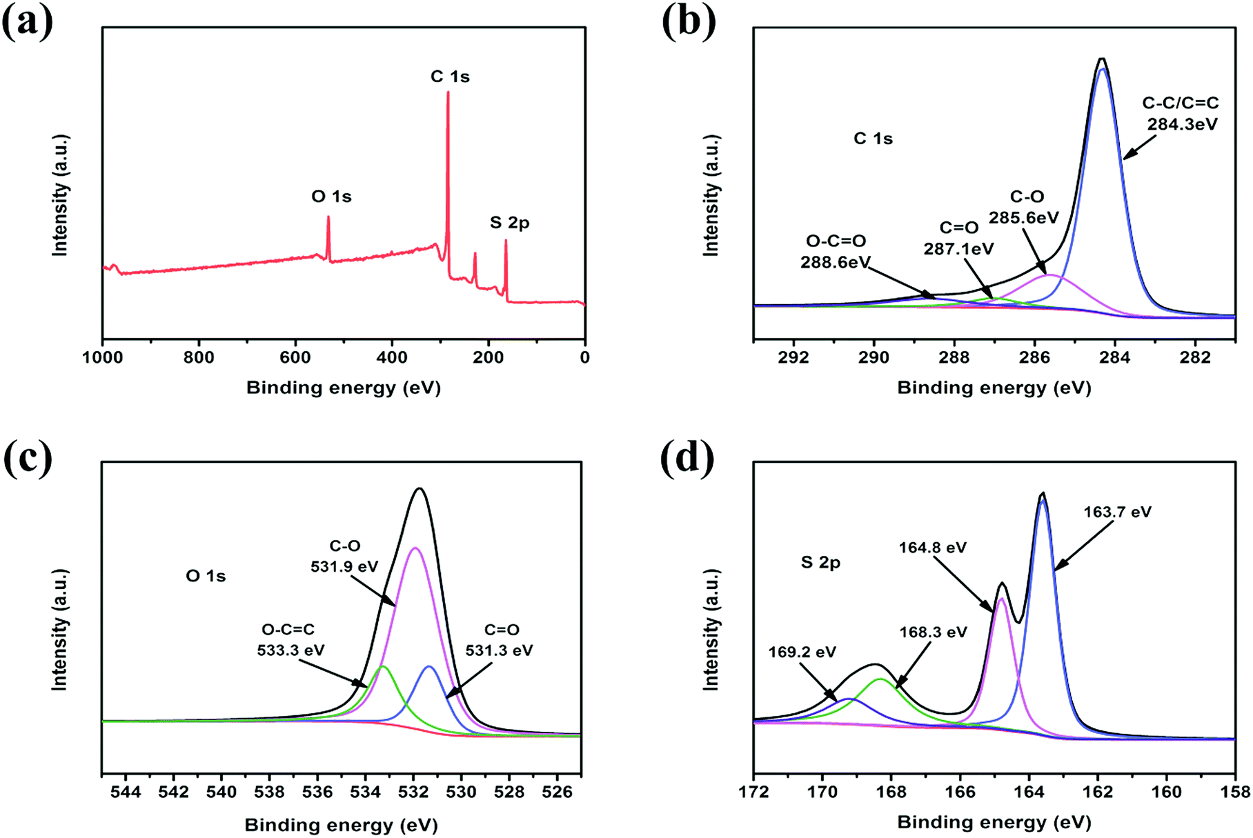 | ||
| Fig. 5 XPS spectra of the c-MNS/S40: (a) survey, (b) C1s, (c) O 1s and (d) S 2p. | ||
The cycling performances of the c-MNS/S composites at 0.1C are shown in Fig. 6a. After the irreversible capacity loss in several of the initial cycles, c-MNS/S25 and c-MNS/S40 both exhibit stable cycling performances, and the difference in their specific capacities is due to the different sulfur loading. However, c-MNS/S60 suffers from constant capacity fading because of the dissolution of high order polysulfides. The discharge capacities of c-MNS/S25, c-MNS/S40, and c-MNS/S60 are 557, 998, and 535 mA h g−1 after 100 cycles, respectively, with the corresponding capacity retentions being 61, 80, and 65%, based on their discharge capacities in the second cycle. A slightly fluctuating coulombic efficiency of c-MNS/S40 of ∼100% during the cycling test demonstrates its outstanding reversibility because the S2–4 molecules are constrained within the ultra-micropores, and hence, the dissolution of polysulfides is effectively prevented.38Fig. 6b presents the rate capabilities of the c-MNS/S composites at 0.1C, 0.2C, 0.5C, 1C, and 2C rates, and finally the discharge–charge rate was turned back to 0.1C to determine their capacity retentions. The specific capacities of the prepared composites decrease with an increase in the discharge–charge rate, owing to electrochemical polarization at heavy currents, and the corresponding typical discharge–charge profiles of the prepared c-MNS/S composites are shown in Fig. S5a–c.† The composite of c-MNS/S40 exhibits the best rate capability, delivering discharge capacities of 1094, 899, 714, 597, and 540 mA h g−1 at 0.1C, 0.2C, 0.5C, 1C, and 2C rates, respectively. The specific capacity of c-MNS/S40 returns to 1074 mA h g−1 when the discharge–charge rate is switched back from 2C to 0.1C, and the specific capacity even remains at 540 mA h g−1 after 500 cycles at 2C (Fig. 6c), which confirms the desirable cycling stability of c-MNS/S40 at a high rate. This is because of the feasibility of using the electrochemical reaction of chain-like S2–4 molecules, owing to the majority of ultra-micropores in the porous structure of c-MNS. Upon comparing the electrochemical performances of previously studied bio-mass-derived carbons used as the hosts of Li–S battery cathodes (Table S2†), it is apparent that c-MNS/S40 has superior cycling stability, which demonstrates the advantage of ultra-microporous c-MNS as a sulfur host for high performance Li–S batteries.
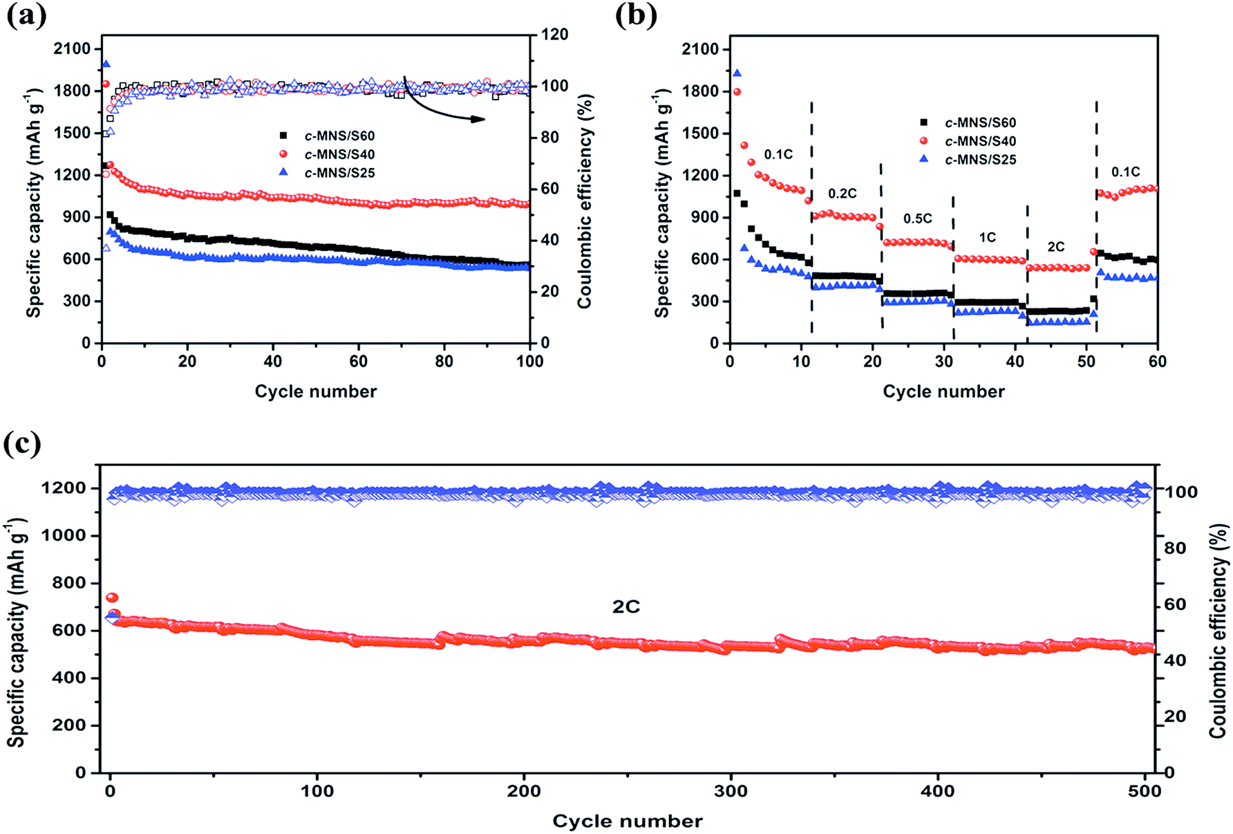 | ||
| Fig. 6 (a) Cycling performances of c-MNS/S25, c-MNS/S40 and c-MNS/S60 at 0.1C, (b) rate performances of c-MNS/S25, c-MNS/S40 and c-MNS/S60, and (c) long cycling performance with coulombic efficiency of the c-MNS/S40 electrode at 2C. | ||
Moreover, compared with other artificially synthesized ultra-microporous carbon materials, c-MNS exhibits superiorities in convenient synthesis, low cost, and sustainability, as well as commercial availability.39–43
In order to investigate the different electrochemical mechanisms of the prepared c-MNS/S composites, EIS was used to study their kinetic parameters. Fig. 7 displays the Nyquist plots of the c-MNS/S composites for the charged state after 100 cycles at 0.1C, which consist of a depressed semicircle in the high frequency region and an inclined line in the low frequency region.
 | ||
| Fig. 7 EIS profiles of the c-MNS/S25, c-MNS/S40 and c-MNS/S60 after 100 cycles at 0.1C; inset: the electron equivalent circuit. | ||
The onset point of the semicircle in The Nyquist plot is correlated to the bulk resistance (Rb) of the fabricated cell, the diameter of the semicircle in the high frequency region reflects the charge transfer resistance (Rct) of the corresponding electrochemical reaction, and the straight line in the low frequency region is attributed to the diffusion of Li+ in the electrode.44 The simulated Rct values according to the equivalent circuit (inset of Fig. 7) are 72.19, 66.43, and 91.12 Ω for c-MNS/S25, c-MNS/S40, and c-MNS/S60, respectively. The smallest Rct value of c-MNS/S40 is an indication of its best rate performance.
In addition, the morphology of the c-MNS/S40 electrode after 100 cycles at 0.1C rate (Fig. 8a) is similar to its original morphology (Fig. 8b), though the rougher surface is caused by the formation of the SEI film. In order to clearly compare the morphology changes, the SEM images with a higher magnification are shown in Fig. S6.† EDS was performed to investigate the elemental distribution of c-MNS/S40 after the cycling test (Fig. 8c), and the corresponding elemental mappings of C, O, and S are shown in Fig. 8d–f, respectively. After cycling, the uniform dispersion of sulfur is maintained, and the clear edge of the sulfur mapping profile confirms its excellent entrapment in the c-MNS host. The TEM image of c-MNS/S40 after the cycling test (Fig. 8g) also exhibits a flake-like morphology with a roughened surface owing to the formed SEI film, and the obscure rings of the corresponding SAED pattern (inset of Fig. 8g) also indicate the amorphous nature of sulfur, confirming the structural stability of c-MNS/S40 after the cycling test.45
 | ||
| Fig. 8 SEM images in low magnification of the c-MNS/S40 cathode after (a) and before (b) 100 discharge–charge cycles at 0.1C, (c) SEM image in high magnification of the cycled c-MNS/S40 cathode and the corresponding EDS mapping images of (d) carbon, (e) oxygen and (f) sulfur, and (g) TEM image, inset of (g): SAED pattern. | ||
Conclusions
In summary, ultra-microporous carbon materials were prepared by the calcination of waste MNSs with the aid of a KOH etching process. The obtained c-MNS was found to have a high ultra-micropore specific surface area ranging up to 1353 m2 g−1 and a large ultra-micropore volume of 0.35 cm3 g−1, which were exploited to accommodate chain-like S2–4 molecules to obtain high-performance cathodes for Li–S batteries. The c-MNS/S40 cathode with a high sulfur mass loading of up to 41%, obtained by optimizing the components of the c-MNS/S composite, exhibited the highest specific capacity (1254 mA h g−1 in the second discharge process at 0.1C), excellent cycling stability (capacity retention of 80% after 100 cycles at 0.1C), and the best rate capability (540 mA h g−1 at 2C). The superior electrochemical performance of c-MNS/S40 is attributed to the highly ultra-microporous scaffold, which effectively traps chain-like S2–4 molecules and alleviates the dissolution of high order polysulfides. This approach provides a low-cost and feasible sulfur host for high performance Li–S batteries, and this kind of ultra-microporous carbon can be easily scaled up because of the accessible raw material and the convenient synthetic procedure.Conflicts of interest
There are no conflicts to declare.Acknowledgements
This work was financially supported by the National Key R&D Program of China (No. 2016YFA0202302), the State Key Program of National Natural Science Foundation of China (No. 51633007), National Natural Science Funds for Distinguished Young Scholars (No. 51425306), and the National Natural Science Foundation of China (No. 51573125 and 51773147).References
- X. Fang and H. S. Peng, Small, 2015, 13, 1488–1511 CrossRef PubMed.
- A. Manthiram, Y. Z. Fu, S. H. Chung, C. Zu and Y. S. Su, Chem. Rev., 2014, 23, 11751–11787 CrossRef PubMed.
- V. S. Kolosnitsyn, E. V. Kuzmina and E. V. Karaseva, J. Power Sources, 2015, 274, 203–210 CrossRef.
- D. W. Wang, Q. C. Zeng, G. M. Zhou, L. C. Yin, F. Li, H. M. Cheng, I. R. Gentle, G. Qing and M. Lu, J. Mater. Chem. A, 2013, 33, 9382–9394 Search PubMed.
- W. Y. Li, Q. F. Zhang, G. Y. Zheng, Z. W. Seh, H. B. Yao and Y. Cui, Nano Lett., 2013, 11, 5534–5540 CrossRef PubMed.
- X. Liang and L. F. Nazar, ACS Nano, 2016, 4, 4192–4198 CrossRef PubMed.
- G. Y. Xu, B. Ding, L. F. Shen, P. Nie, J. P. Han and X. G. Zhang, J. Mater. Chem. A, 2013, 14, 4490–4496 Search PubMed.
- Z. Li, Y. M. Huang, L. X. Yuan, Z. X. Hao and Y. H. Huang, Carbon, 2015, 92, 41–63 CrossRef.
- X. L. Ji, K. T. Lee and L. F. Nazar, Nat. Mater., 2009, 6, 500–506 CrossRef PubMed.
- S. Xin, L. Gu, N. H. Zhao, Y. X. Yin, L. J. Zhou, Y. G. Guo and L. J. Wan, J. Am. Chem. Soc., 2012, 45, 18510–18513 CrossRef PubMed.
- S. G. Zhang, K. Ueno, K. Dokko and M. Watanabe, Adv. Energy Mater., 2015, 5, 1500117–1500144 CrossRef.
- B. Zhang, X. Qin, G. R. Li and X. P. Gao, Energy Environ. Sci., 2010, 10, 1531–1537 Search PubMed.
- L. Hu, Y. Lu, X. N. Li, J. W. Liang, T. Huang, Y. C. Zhu and Y. T. Qian, Small, 2017, 11, 1603533–1603543 CrossRef PubMed.
- Z. Li, L. X. Yuan, Z. Q. Yi, Y. M. Sun, Y. Liu, Y. Jiang, Y. Shen, Y. Xin, Z. L. Zhang and Y. H. Huang, Adv. Energy Mater., 2014, 7, 1301473–1301481 CrossRef.
- Z. H. Peng, W. Y. Fang, H. B. Zhao, J. H. Fang and H. W. Cheng, J. Power Sources, 2015, 282, 70–78 CrossRef.
- A. Ahmadpour and D. D. Do, Carbon, 1997, 12, 1723–1732 CrossRef.
- Y. S. Su and A. Manthiram, Nat. Commun., 2012, 3, 1166–1172 CrossRef PubMed.
- B. Zhang, M. Xiao, S. J. Wang, D. M. Han, S. Q. Song, G. H. Chen and Y. Z. Meng, ACS Appl. Mater. Interfaces, 2014, 15, 13174–13182 Search PubMed.
- J. C. Wang and S. Kaskel, J. Mater. Chem., 2012, 45, 23710–23725 RSC.
- H. Ye, Y. X. Yin, S. Xin and Y. G. Guo, J. Mater. Chem. A, 2013, 22, 6602–6608 Search PubMed.
- Q. Z. Zhu, Q. Zhao, Y. B. An, B. Anasori, H. R. Wang and B. Xu, Nano Energy, 2017, 33, 402–409 CrossRef.
- K. Balakumar, R. Sathish and N. Kalaiselvi, Electrochim. Acta, 2016, 209, 171–182 CrossRef.
- S. R. Zhao, C. M. Li, W. K. Wang, H. Zhang, M. Y. Gao, X. Xiong, A. B. Wang, K. G. Yuan, Y. Q. Huang and F. Wang, J. Mater. Chem. A, 2013, 10, 3334–3339 Search PubMed.
- S. Z. Niu, G. M. Zhou, W. Lv, H. F. Shi, C. Luo, Y. B. He, B. H. Li, Q. H. Yang and F. Y. Kang, Carbon, 2016, 109, 1–6 CrossRef.
- N. Moreno, A. Caballero, L. Hernan and J. Morales, Carbon, 2014, 70, 241–248 CrossRef.
- M. Cuisinier, P. E. Cabelguen, B. D. Adams, A. Garsuch, M. Balasubramanian and L. F. Nazar, Energy Environ. Sci., 2014, 8, 2697–2705 Search PubMed.
- X. Li, X. B. Cheng, M. X. Gao, D. W. Ren, Y. F. Liu, Z. X. Guo, C. X. Shang, L. X. Sun and H. G. Pan, ACS Appl. Mater. Interfaces, 2017, 12, 10717–10729 Search PubMed.
- J. Chmiola, G. Yushin, Y. Gogotsi, C. Portet, P. Simon and P. L. Taberna, Science, 2006, 5794, 1760–1765 CrossRef PubMed.
- M. Helen, M. A. Reddy, T. Diemant, U. G. Schindler, R. J. Behm, U. Kaiser and M. Fichtner, Sci. Rep., 2015, 5, 12146–12158 CrossRef PubMed.
- J. C. Guo, Y. H. Xu and C. S. Wang, Nano Lett., 2011, 10, 4288–4294 CrossRef PubMed.
- K. Mi, Y. Jiang, J. K. Feng, Y. T. Qian and S. L. Xiong, Adv. Funct. Mater., 2016, 10, 1571–1579 CrossRef.
- A. Rosenman, E. Markervich, G. Salitra, Y. Talyosef, F. Chesneau and D. Aurbach, J. Electrochem. Soc., 2016, 9, 1829–1835 CrossRef.
- E. Markevich, G. Salitra, A. Rosenman, Y. Talyosef, F. Chesneau and D. Aurbach, J. Mater. Chem. A, 2015, 3, 19873–19883 Search PubMed.
- Y. J. Zhong, S. F. Wang, Y. J. Sha, M. L. Liu, R. Cai, L. Li and Z. P. Shao, J. Mater. Chem. A, 2016, 24, 9526–9535 Search PubMed.
- M. Cuisinier, P. E. Cabelguen, B. D. Adams, A. Garsuch, M. Balasubramanian and L. F. Nazar, Energy Environ. Sci., 2014, 8, 2697–2705 Search PubMed.
- Y. Diao, K. Xie, S. Z. Xiong and X. B. Hong, J. Electrochem. Soc., 2012, 11, 1816–1821 CrossRef.
- Z. Li, Y. Jiang, L. X. Yuan, Z. Q. Yi, C. Wu, Y. Liu, P. Strasser and Y. H. Huang, ACS Nano, 2014, 9, 9295–9303 CrossRef PubMed.
- Y. H. Xu, Y. Wen, Y. J. Zhu, K. Gaskell, K. A. Cychosz, B. Eichhorn, K. Xu and C. S. Wang, Adv. Funct. Mater., 2015, 27, 4312–4320 CrossRef.
- Z. Gao, Y. Y. Zhang, N. N. Song and X. D. Li, Mater. Res. Lett., 2017, 2, 69–88 CrossRef.
- J. L. Wang, Y. S. He and J. Yang, Adv. Mater., 2015, 27, 569–575 CrossRef PubMed.
- H. Zhang, Z. B. Zhao, Y. Liu, J. J. Liang, Y. N. Hou, Z. C. Zhang, X. Z. Wang and J. S. Qiu, J. Energy Chem., 2017, 26, 1282–1290 CrossRef.
- H. J. Peng, J. Q. Huang, M. Q. Zhao, Q. Zhang, X. B. Cheng, X. Y. Liu, W. Z. Qian and F. Wei, Adv. Funct. Mater., 2014, 24, 2772–2781 CrossRef.
- G. P. Hao, C. Tang, E. Zhang, P. Y. Zhai, J. Yin, W. C. Zhu, Q. Zhang and S. Kaskel, Adv. Mater., 2015, 27, 29–35 Search PubMed.
- X. M. Ye, J. Ma, Y. S. Hu, H. Y. Wei and F. F. Ye, J. Mater. Chem. A, 2016, 3, 775–780 Search PubMed.
- E. Markevich, G. Salitra, Y. Talyosef, F. Chesneau and D. Aurbach, J. Electrochem. Soc., 2017, 1, 6244–6253 CrossRef.
Footnote |
| † Electronic supplementary information (ESI) available. See DOI: 10.1039/c8se00185e |
| This journal is © The Royal Society of Chemistry 2018 |