MOFs as an electron-transfer-bridge between a dye photosensitizer and a low cost Ni2P co-catalyst for increased photocatalytic H2 generation†
Li
Wu‡
a,
Youchi
Tong‡
a,
Lina
Gu
a,
Zhaoming
Xue
a and
Yupeng
Yuan
 *ab
*ab
aSchool of Chemistry and Chemical Engineering, Anhui Province Key Laboratory of Chemistry for Inorganic/Organic Hybrid Functionalized Materials, Anhui University, Hefei 230601, P. R. China. E-mail: yupengyuan@ahu.edu.cn
bInstitute of Physical Science and Information Technology, Anhui University, Hefei 230601, P. R. China
First published on 14th May 2018
Abstract
Weak interaction results in inefficient electron transfer from the photoexcited erythrosin B dye photosensitizer to H2 generation co-catalyst Ni2P, thereby leading to low H2 generation. To address this issue, UiO-66 MOFs were used as a suitable medium for enhancing the electron transfer process. The strong π–π interaction between the benzene rings of erythrosin B dye and UiO-66 ensures efficient electron transfer from the photoexcited erythrosin B dye to UiO-66. In addition, UiO-66 can serve as the substrate for growing the Ni2P co-catalyst. As a result, the erythrosin B dye/UiO-66/Ni2P system offers efficient electron transfer from erythrosin B dye to UiO-66, and to Ni2P, thereby resulting in an active H2 generation when compared to the erythrosin B dye and Ni2P system. The erythrosin B dye/UiO-66/Ni2P system with an optimum Ni2P amount of 0.69 wt% exhibits the highest H2 evolution rate of 65 μmol h−1. This value is nearly 5 times higher than that of the reference system without UiO-66 (13.8 μmol h−1). The present results show the great potential of MOFs as a porous medium for enhancing the photocatalytic H2 generation performance of conventional systems containing a photosensitizer and H2 generation co-catalyst.
Introduction
Photocatalytic H2 generation is one of the most promising solutions to problems of energy shortage and environmental pollution.1–7 The systems developed for photocatalytic H2 generation always contain three parts: a photosensitizer for light absorption, a noble-metal-based co-catalyst for catalyzing H2 generation, and a sacrificial electron donor for capturing holes photogenerated by the photosensitizer.8,9 Presently, molecular dyes and noble metals are widely used to construct photocatalytic systems for H2 generation despite the low efficiency. The low H2 generation results from the insufficient charge transfer from photoexcited dyes to noble metals due to their weak interactions. To address this issue, an inorganic catalyst, such as TiO2, was used as a medium to strengthen the interaction between dyes and noble metals as TiO2 can serve as the substrate for dye absorption and co-catalyst loading.10–16 However, the low absorption capacity of TiO2 and weak interaction between TiO2 and dyes show a less than anticipated enhancement in H2 generation.17,18MOFs are one of the most suitable media for bridging photosensitizers and H2 generation co-catalysts.19,20 MOFs are porous solids that are crystallized using metal ions and organic linkers. Compared to TiO2, the advantages of using MOFs as a substrate for absorbing dyes and loading co-catalysts are twofold. First, MOFs have a large surface area and high pore volume, thus leading to a high absorption capacity for dyes. In addition, there exists strong π–π interaction between the benzene rings of MOFs and dyes, further improving the interaction between MOFs and dyes.19,21 Consequently, the high adsorption capacity and strong π–π interaction ensure efficient charge transfer from photoexcited dyes to MOFs. Second, the functionalized organic linkers make MOFs a suitable substrate for growing inorganic co-catalysts. As a result, efficient charge transfer from photoexcited dyes to MOFs and then to co-catalysts for H2 generation is expected in principle.
Herein we report a H2 generation system containing erythrosin B dye, UiO-66 MOFs, and non-noble metal co-catalyst Ni2P. This H2 generation system has two advantages. First, MOFs were used as the “bridging medium” for enhancing the charge transfer from the photoexcited dye to the H2 generation co-catalyst in spite of the fact that MOFs are photocatalysts for H2 generation under UV/vis light irradiation.22–26 Second, the co-catalyst is Ni2P rather than noble metals, such as Pt. Transition-metal phosphides (TMPs) have been a focus of research in electrochemical catalysis due to their noble-metal-free and earth-abundant nature despite their relatively low electrocatalytic activity compared to noble metals.27–30 The erythrosin B dye/UiO-66/Ni2P system shows a H2 generation rate of 65 μmol h−1, which is nearly 5 times higher than that of the reference system of erythrosin B dye/Ni2P (13.8 μmol h−1).
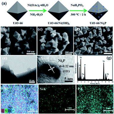
Fig. 1a schematically shows the procedure for UiO-66/Ni2P preparation. UiO-66 octahedra were first prepared, and then Ni(OH)2 was hydrothermally grown on the UiO-66 surface. Finally, Ni(OH)2 was in situ converted to nickel phosphide (Ni2P) nanoparticles by phosphating Ni(OH)2/UiO-66 composites at 300 °C for 2 h in an Ar atmosphere. The obtained products were denoted as UiO-66/Ni2P-x (x is the Ni2P weight ratio in the hybrids, and was determined to be x = 0.35, 0.69, 1.38, and 2.76 wt% from the amount of Ni2+ added, assuming that Ni2+ ions were totally converted to Ni2P and the amount of UiO-66 remained unchanged). Pristine UiO-66 is composed of octahedral microcrystals with an edge length of 200 to 500 nm (Fig. 1b). Ni(OH)2 loading does not change the morphology of UiO-66 octahedra (Fig. 1c). The SEM image does not show the presence of Ni(OH)2 particles on the surface of UiO-66 octahedra. However, the EDS result clearly confirms the presence of Ni as shown in Fig. S1.† In sharp contrast, several particles were observed on the surface of UiO-66 octahedra after phosphating the UiO-66/Ni(OH)2 composites at 300 °C for 2 h in an Ar atmosphere (Fig. 1d). These small particles should be derived from Ni(OH)2 as pristine UiO-66 octahedra retain their very smooth and clean surfaces after being thermally treated under the same conditions (Fig. S2†) as UiO-66 can be thermally stable up to 500 °C in Ar as shown in Fig. S3.†
The small Ni2P particles on UiO-66 octahedra were further examined by TEM analysis (Fig. 1e). These small particles are Ni2P as supported by high resolution TEM (HRTEM) analysis (Fig. 1f). HRTEM reveals a lattice fringe of 0.22 nm, indexed to the (111) planes of Ni2P.31 Ni2P nanoparticles about 20 nm in diameter were found to be intimately adhering to the surface of UiO-66 octahedra (Fig. 1e). A clear interface between UiO-66 and Ni2P was formed during phosphating Ni(OH)2, which is very important for efficient charge transfer between UiO-66 and Ni2P and is thereby expected to improve the photocatalytic hydrogen production. EDS shows a molar ratio of 2.4![[thin space (1/6-em)]](https://www.rsc.org/images/entities/char_2009.gif) :
:![[thin space (1/6-em)]](https://www.rsc.org/images/entities/char_2009.gif) 1 for Ni2P (Fig. 1g), which is very close to the theoretical ratio of 2
1 for Ni2P (Fig. 1g), which is very close to the theoretical ratio of 2![[thin space (1/6-em)]](https://www.rsc.org/images/entities/char_2009.gif) :
:![[thin space (1/6-em)]](https://www.rsc.org/images/entities/char_2009.gif) 1. The uniform distribution of Ni2P on UiO-66 was further supported by elemental mapping (Fig. 1h).
1. The uniform distribution of Ni2P on UiO-66 was further supported by elemental mapping (Fig. 1h).
The XRD patterns of UiO-66/Ni2P are shown in Fig. 2a. The XRD pattern of pristine UiO-66 has very sharp diffraction peaks, and all peaks can be indexed to UiO-66.32 No peaks of byproducts were detected during the phosphating process for Ni2P formation. No peaks can be indexed to Ni2P likely owing to the low loading amount. The peaks at 30.5°, 40.8°, 44.6°, 47.3° and 54.4° are indexed to the (110), (111), (021), (210) and (002) facets, respectively. The XRD peaks are well matched with those of Ni2P (JCPDS#65-3544). FT-IR analysis (Fig. 2b) further supports the unchanged crystal structure of UiO-66 after Ni2P formation. XPS analysis was performed to further examine the characteristics of UiO-66/Ni2P-0.69%. Fig. 2c and d show the Ni 2p and P 2p high-magnification XPS spectra, respectively. The two peaks at 853.8 and 856.8 eV for Ni 2p3/2 correspond to Niδ+ and Ni2+ of Ni2P, respectively.33,34 The peak at around 862.3 eV is the satellite of Ni 2p3/2.35 Similarly, two peaks are observed at around 874.3 and 881.5 eV for the Ni 2p1/2 level, which are attributed to the Ni2+ and satellite of Ni2P, respectively.33 In the P 2p XPS spectrum (Fig. 2d), the peak at 133.4 eV corresponds to P 2p1/2.36 These results clearly indicate the presence of Ni2P in the obtained products.
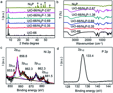 | ||
| Fig. 2 (a) XRD patterns and (b) FT-IR spectra of the UiO-66/Ni2P-x (x = 0.35, 0.69, 1.38, and 2.76 wt%) hybrids, pristine UiO-66 and Ni2P. XPS spectra of (c) Ni 2p and (d) P 2p for UiO-66/Ni2P-0.69%. | ||
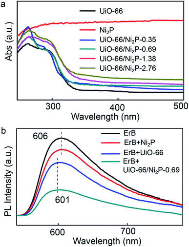
The UV/Vis absorption spectra of pristine UiO-66, Ni2P, and the UiO-66/Ni2P composites are compared in Fig. 3a. Pristine UiO-66 exhibits an ultraviolet light absorption edge of 350 nm, corresponding to a 3.5 eV band gap.20 The UiO-66/Ni2P composites also show the typical optical absorption behaviour of UiO-66 with an absorption edge of 350 nm. In addition, Ni2P loading results in intense light absorption in the visible light region. The more intense light absorption with increasing Ni2P loading supports the increased Ni2P content in UiO-66/Ni2P composites as exemplified by the Ni2P absorption spectrum.
Effective electron transfer depends largely on interactions among erythrosin B dye, UiO-66 MOFs, and the Ni2P co-catalyst. In this context, the steady-state photoluminescence (PL) upon excitation at 450 nm was measured in order to reveal the electron transfer among erythrosin B dye, UiO-66 MOFs, and Ni2P (Fig. 3b). Erythrosin B dye alone has a strong PL peak at 606 nm. In sharp contrast, UiO-66 addition significantly quenches this peak, verifying the efficient charge transfer from the photoexcited erythrosin B dye to UiO-66. Notably, the blue-shift of the PL peak from 606 nm to 601 nm further reveals the strong interaction between erythrosin B dye and UiO-66 MOFs. Moreover, Ni2P integration further decreases this PL peak, supporting the efficient electron transfer from erythrosin B dye to UiO-66, and then to Ni2P.
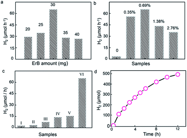
To uncover the effect of UiO-66 incorporation on H2 generation, the erythrosin B/UiO-66/Ni2P system was tested for visible-light-response photocatalytic H2 generation from water reduction. TEOA (10%) was used as the sacrificial electron donor. For utilizing visible light, erythrosin B dye was chosen to photosensitize UiO-66 owing to the strong interaction between their benzene rings, as revealed by the PL results shown in Fig. 3b. Control experiments show no H2 generation without light irradiation or UiO-66/Ni2P catalysts. The H2 generation rate was dependent on the concentration of erythrosin B. The highest H2 generation rate of 65 μmol h−1 was achieved when using 30 mg of erythrosin B dye for UiO-66/Ni2P (0.69 wt%) in 10 mL 10 vol% TEOA solution (Fig. 4a). All experiments were therefore tested under these conditions.
Fig. 4b shows the average H2 generation rate in the first four hours. The system of erythrosin B dye and Ni2P offers a H2 generation rate of 13.8 μmol h−1 (Fig. 4c). In sharp contrast, the introduction of UiO-66 MOFs leads to a greatly increased H2 generation rate (Fig. 4b and c). For example, the erythrosin B/UiO-66/Ni2P-0.35 system shows a H2 generation rate of 55.7 μmol h−1 (Fig. 4b). This enhancement in H2 generation is substantially benefited by the strong π–π interaction between the benzene rings of UiO-66 and erythrosin B dye, and thereby leads to efficient charge transfer from the photoexcited dye to UiO-66 MOFs. The very low H2 generation from pure UiO-66 (∼3.3 μmol h−1) (Fig. 4b) further validates the essential role of MOFs in bridging the erythrosin B dye and Ni2P co-catalyst. Higher Ni2P coverage on UiO-66 leads to larger interfacial areas, more efficient charge separation and thereby the higher H2 generation rate as exemplified by the H2 generation rate of 65 μmol h−1 observed for the erythrosin B/UiO-66/Ni2P (0.69 wt%) system. This value is nearly 5 times greater than that of the system without UiO-66 MOFs. It is also worth highlighting the necessity of the in situ formation of Ni2P for enhanced H2 generation. A simple physical mixture of Ni2P (0.69 wt%) and UiO-66 shows a H2 generation rate of 15.5 μmol h−1 under the same experimental conditions (Fig. 4c). This result clearly exemplifies the importance of the in situ phosphating process which ensures the formation of tight Ni2P/UiO-66 interfaces for efficient charge transfer from the photoexcited dye to UiO-66 and to Ni2P. However, reduced H2 generation performance is observed when the Ni2P content is further increased to 1.38 wt% (UiO-66/Ni2P-1.38) and 2.76 wt% (UiO-66/Ni2P-2.76) (Fig. 4b). This result is ascribed to the concomitant coverage effect in which the overloading of Ni2P can cause the active sites for H2 evolution to be covered, and thereby hinder the H2 generation as no obvious difference in size and morphology of Ni2P at low (0.35 wt%) and high (2.76 wt%) loading amounts can be observed (Fig. S4†). It is worth noting that there is Na species in the obtained Ni2P/UiO-66 hybrids as shown by the EDS result (Fig. 1g). The Na signal in Fig. 1g should originate from NaH2PO2, which was added as the P source for phosphating UiO-66/Ni(OH)2 to UiO-66/Ni2P. To verify the effect of Na on photocatalytic activity, we tested the H2 generation activity by adding NaH2PO2 (25 mg) into the reaction suspension while keeping other experimental factors unchanged. No evident change in H2 generation was observed (Fig. S5†), validating that Na species in UiO-66/Ni2P hardly contribute to photocatalytic H2 generation despite a slight change of pH value from 9.3 for the original suspension to 10 after NaH2PO2 addition. This result is ascribed to NaOH formation through the reaction of NaH2PO2 with triethanolamine, the sacrificial electron donor.
Ni2P as a non-noble-metal co-catalyst has excellent photo-stability for photocatalytic H2 generation.4,37 To test the stability of Ni2P in the present system, UiO-66/Ni2P-0.69 was used as a representative sample for long term photocatalytic H2 generation. Impressively, UiO-66/Ni2P-0.69 shows a relatively stable H2 generation profile over the duration of a 12 h reaction (Fig. 4d). The slight decrease in H2 evolution is a common phenomenon in dye sensitized photocatalysts for H2 generation as the dye would gradually be consumed and deactivated.38,39 XRD analysis validates the unchanged phase of UiO-66/Ni2P-0.69 before and after 12 h of H2 generation reaction (Fig. S6†). In addition, neither aggregation nor any phase or morphology change for Ni2P was detected after 12 h of long-term H2 generation reaction (Fig. S7†). This result further supports the fact that Ni2P stability plays an important role in boosting H2 generation.
The increased H2 generation is the result of the efficient electron transfer from the photoexcited erythrosin B dye to UiO-66 and then to the Ni2P co-catalyst, as revealed by stable-state PL analysis. It has been reported that the LUMO potential of erythrosin B dye (−0.9 V vs. NHE at pH 7.0)40 is more negative than the conduction band edge of UiO-66 (−0.6 V vs. NHE at pH 7.0).20 In addition, there are strong π–π stacking interactions and van der Waals forces between the benzene rings of erythrosin B dye and UiO-66 MOFs as exemplified by the blue-shift of the photoluminescence peak in Fig. 3b. Moreover, the large surface area of UiO-66 (Fig. S8†) further ensures the large absorption of the dye on MOFs. As consequence, the electrons in the photoexcited erythrosin B dye could thus effectively transfer to UiO-66 MOFs (Fig. S9†). The electrons injected into UiO-66 could further transfer to Ni2P across the UiO-66/Ni2P interfaces created by in situ phosphatation, and the electrons accumulating on Ni2P can reduce H+ to hydrogen.
In order to verify the enhanced charge separation of erythrosin B/UiO-66/Ni2P(0.69 wt%), photoelectrochemical (PEC) I–T curves, electrochemical impedance spectroscopy (EIS) plots, and polarization curves were further measured and are shown in Fig. 5. In Fig. 5a, the photocurrent responses were prompt and reproducible during the on/off cycles of visible-light excitation; the higher photocurrent of erythrosin B/UiO-66/Ni2P-0.69 indicated the fast electron transfer from erythrosin B to UiO-66 to Ni2P and then to ITO glass. Fig. 5b presents the EIS Nyquist plots of erythrosin B/UiO-66 and erythrosin B/UiO-66/Ni2P (0.69 wt%). Since the arc radius of erythrosin B/UiO-66/Ni2P (0.69 wt%) is smaller than that of erythrosin B/UiO-66, it demonstrates that the loaded Ni2P co-catalyst can effectively promote the charge transfer at the photocatalyst/solution interface, corresponding to the result of the enhanced photocatalytic activity. Also from the polarization curves (Fig. 5c), erythrosin B/UiO-66/Ni2P-0.69 exhibits much more pronounced cathodic current density and lower overpotential compared to ErB/UiO-66, which demonstrates that the erythrosin B/UiO-66/Ni2P-0.69 interfaces can efficiently enhance the electron mobility by reducing the recombination of photogenerated carriers, thus presenting the increased hydrogen generation rate.
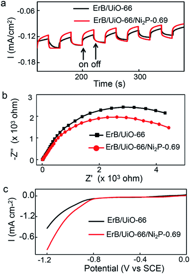 | ||
| Fig. 5 (a) Comparison of transient photocurrent responses under visible-light irradiation, (b) EIS Nyquist plots, and (c) polarization curves of the ErB/UiO-66 and ErB/UiO-66/Ni2P-0.69 hybrids. | ||
In summary, UiO-66 MOFs were exemplified as an excellent electron transfer channel for bridging the erythrosin B dye and Ni2P co-catalyst. The high adsorption capacity, suitable band energy position, and strong π–π interaction with the dye make UiO-66 MOFs a suitable medium for accepting electrons from the photoexcited erythrosin B dye. Moreover, the intimate adhering of Ni2P on UiO-66 octahedra guarantees electron transfer across the interfaces of UiO-66 and Ni2P to Ni2P nanoparticles. This efficient charge transfer process suppresses the recombination of electron–hole pairs, leading to enhanced H2 generation. The present work shows the great potential of MOFs for photocatalytic H2 generation.
Conflicts of interest
There are no conflicts to declare.Acknowledgements
This work was financially supported by the National Natural Science Foundation of China (51572003) and Anhui Provincial Natural Science Foundation (1508085ME105). Dr Yuan acknowledges the financial support of SRF for ROCS, SEM, and the Technology Foundation for Selected Overseas Chinese Scholars.Notes and references
- K. Maeda, K. Teramura, D. Lu, T. Takata, N. Saito, Y. Inoue and K. Domen, Nature, 2006, 440, 295 CrossRef PubMed.
- Y. P. Yuan, L. W. Ruan, J. Barber, S. C. J. Loo and C. Xue, Energy Environ. Sci., 2014, 7, 3934–3951 Search PubMed.
- J. Ran, J. Zhang, J. Yu, M. Jaroniec and S. Z. Qiao, Chem. Soc. Rev., 2014, 43, 7787–7812 RSC.
- Z. Sun, H. Zheng, J. Li and P. Du, Energy Environ. Sci., 2015, 8, 2668–2676 Search PubMed.
- X. Li, J. Yu and M. Jaroniec, Chem. Soc. Rev., 2016, 45, 2603–2636 RSC.
- R. B. Wei, Z. L. Huang, G. H. Gu, Z. Wang, L. Zeng, Y. Chen and Z. Q. Liu, Appl. Catal., B, 2018, 231, 101–107 CrossRef.
- C. Huang, T. Ouyang, Y. Zou, N. Li and Z. Q. Liu, J. Mater. Chem. A, 2018, 6, 7420–7427 Search PubMed.
- X. Chen, S. Shen, L. Guo and S. S. Mao, Chem. Rev., 2010, 110, 6503–6570 CrossRef PubMed.
- A. Kudo and Y. Miseki, Chem. Soc. Rev., 2009, 38, 253–278 RSC.
- Y. Li, M. Guo, S. Peng, G. Lu and S. Li, Int. J. Hydrogen Energy, 2009, 34, 5629–5636 CrossRef.
- X. Liu, Y. Li, S. Peng, G. Lu and S. Li, Photochem. Photobiol. Sci., 2013, 12, 1903–1910 Search PubMed.
- Y. Li, C. Xie, S. Peng, G. Lu and S. Li, J. Mol. Catal. A: Chem., 2008, 282, 117–123 CrossRef.
- M. Ye, M. Wang, D. Zheng, N. Zhang, C. Lin and Z. Lin, Nanoscale, 2014, 6, 3576–3584 RSC.
- M. Wang, D. Zheng, M. Ye, C. Zhang, B. Xu, C. Lin, L. Sun and Z. Lin, Small, 2015, 11, 1436–1442 CrossRef PubMed.
- M. Wang, L. Sun, Z. Lin, J. Cai, K. Xie and C. Lin, Energy Environ. Sci., 2013, 6, 1211–1220 Search PubMed.
- M. Wang, X. Pang, D. Zheng, Y. He, L. Sun, C. Lin and Z. Lin, J. Mater. Chem. A, 2016, 4, 7190–7199 Search PubMed.
- R. Abe, K. Hara, K. Sayama, K. Domen and H. Arakawa, J. Photochem. Photobiol., A, 2000, 137, 63–69 CrossRef.
- R. Abe, K. Sayama and H. Arakawa, J. Photochem. Photobiol., A, 2004, 166, 115–122 CrossRef.
- X. L. Liu, R. Wang, M. Y. Zhang, Y. P. Yuan and C. Xue, APL Mater., 2015, 3, 37 Search PubMed.
- Y. P. Yuan, L. S. Yin, S. W. Cao, G. S. Xu, C. H. Li and C. Xue, Appl. Catal., B, 2015, 168–169, 572–576 CrossRef.
- J. He, J. Wang, Y. Chen, J. Zhang, D. Duan, Y. Wang and Z. Yan, Chem. Commun., 2014, 50, 7063 RSC.
- L. Jiao, Y. Wang, H. L. Jiang and Q. Xu, Adv. Mater., 2017, 1703663 CrossRef PubMed.
- Z. Li, J. Xiao and H. Jiang, ACS Catal., 2016, 6, 5359–5365 CrossRef.
- X. Fang, Q. Shang, Y. Wang, L. Jiao, T. Yao, Y. Li, Q. Zhang, Y. Luo and H. L. Jiang, Adv. Mater., 2018, 1705112 CrossRef PubMed.
- J. D. Xiao and H. L. Jiang, Small, 2017, 13, 1700632 CrossRef PubMed.
- J. D. Xiao, Q. Shang, Y. Xiong, Q. Zhang, Y. Luo, S. H. Yu and H. L. Jiang, Angew. Chem., 2016, 128, 9535–9539 CrossRef.
- P. Liu and J. A. Rodriguez, J. Am. Chem. Soc., 2005, 127, 14871–14878 CrossRef PubMed.
- X. Zhu, M. Liu, Y. Liu, R. Chen, Z. Nie, J. Li and S. Yao, J. Mater. Chem. A, 2016, 4, 8974–8977 Search PubMed.
- Y. Pan, N. Yang, Y. Chen, Y. Lin, Y. Li, Y. Liu and C. Liu, J. Power Sources, 2015, 297, 45–52 CrossRef.
- L. Yan, P. Dai, W. Ying, G. Xin, L. Li, C. Lei and X. Zhao, ACS Appl. Mater. Interfaces, 2017, 9, 11642 Search PubMed.
- R. K. Chiang and R. T. Chiang, Inorg. Chem., 2007, 46, 369–371 CrossRef PubMed.
- M. Kandiah, M. H. Nilsen, S. Usseglio, S. Jakobsen, U. Olsbye, M. Tilset, C. Larabi, E. A. Quadrelli, F. Bonino and K. P. Lillerud, Chem. Mater., 2010, 22, 6632–6640 CrossRef.
- Y. Zhao, Y. Zhao, H. Feng and J. Shen, J. Mater. Chem., 2011, 21, 8137–8145 RSC.
- D. P. Kumar, J. Choi, S. Hong, D. A. Reddy, S. Lee and T. K. Kim, 2016, 4, 7158–7166.
- A. N. Mansour, Surf. Sci. Spectra, 1994, 3, 239–246 CrossRef.
- A. P. Grosvenor, S. D. Wik, R. G. Cavell and A. Mar, Inorg. Chem., 2006, 37, 8988–8998 Search PubMed.
- G. F. Chen, T. Y. Ma, Z. Q. Liu, N. Li, Y. Z. Su, K. Davey and S. Z. Qiao, Adv. Funct. Mater., 2016, 26, 3314–3323 CrossRef.
- W. Zhang, J. Hong, J. Zheng, Z. Huang, J. Zhou and R. Xu, J. Am. Chem. Soc., 2011, 133, 20680 CrossRef PubMed.
- W. Zhang and R. Xu, Int. J. Hydrogen Energy, 2012, 37, 17899–17909 CrossRef.
- Y. Wang, J. Hong, W. Zhang and R. Xu, Catal. Sci. Technol., 2013, 3, 1703–1711 Search PubMed.
Footnotes |
| † Electronic supplementary information (ESI) available: SEM and TEM images; XRD patterns; N2 adsorption–desorption isotherm; XPS spectra; and TG analysis. See DOI: 10.1039/c8se00168e |
| ‡ Li Wu and Youchi Tong contributed equally to this work. |
| This journal is © The Royal Society of Chemistry 2018 |

