
Portable smart highly proton conductive all inorganic gel paste electrolyte with optimum phosphorous to silicon ratio for enhanced durable operation of a fuel cell†
Priyanka
Ghosh
a,
Chandan Kumar
Dhole
a,
Saibal
Ganguly
b,
Dipali
Banerjee
 c and
Kajari
Kargupta
*a
c and
Kajari
Kargupta
*a
aChemical Engineering Department, Jadavpur University, Kolkata, India. E-mail: karguptakajari2011@gmail.com
bChemical Engineering Department, BITS PILANI, Goa Campus, India
cDepartment of Physics, Indian Institute of Engineering Science and Technology (I.I.E.S.T), Shibpur, West Bengal, India
First published on 21st June 2018
Abstract
Portable smart low-cost proton conductive gel paste electrolytes, capable of retaining their properties over a few months and of being stored, are of significance in the context of portable fuel cell power sources. A low-cost, sol gel derived inorganic gel paste electrolyte with an optimum phosphorous to silicon ratio of five, whose proton conductivity exceeds Nafion in the broad temperature range of 50–180 °C, is reported herein. The fuel cell assembled with this gel paste coated on a glass mat, operating at a temperature of 160 °C, produces a maximum current density of >1 A cm−2, a power density of >210 mW cm−2 and offers stable durable operation up to 29 hours under a 50 mA cm−2 load. The significance of these findings is that the gel paste may be used to replace conventional liquid and membrane electrolytes in fuel cells and be applied in new generation electronics with portable fuel cells.
1. Introduction
Portable conductive materials are of great interest for next generation renewable energy sources and storage materials, electronics, devices, and sensors, etc.1–3 With the increasing demand for pollution-free renewable green energy, scientists are trying to develop smart materials with low cost, easy synthetic pathways and effective applications. Exhaustive studies on conductive hydrogels have been undertaken over the last few decades. However, the literature on portable, smart, capable of being stored, all inorganic proton conductive hydrogels is still scant. Proton conductive, all inorganic gel pastes have wide potential and are the most attractive type due to their high surface area, three dimensional porous structure, excellent liquid–solid interfaces, tunnelling pathways for transportation, unique electrical and electrochemical properties and in particular, their superb conductivity.4–8 These portable smart gels can be effectively used in the field of renewable energy resources, such as fuel cell, batteries, super capacitors, etc. They may be appropriately used in portable power sources for on board power requirement in vehicles and in powering remote electronic devices.Conductive gels are generally synthesized by incorporating conducting particles such as conducting polymers, graphene, carbon nanotubes (CNT), etc. into the gel matrix.9,10 On the contrary, proton conductive gels can be synthesized by trapping acid into organic or inorganic matrices.11,12 Among the different acids, phosphoric acid contains three protons per molecule and therefore offers the best proton conductivity. The potential application of a proton conductive gel is to replace the conventionally used phosphoric acid liquid electrolyte of phosphoric acid fuel cells (PAFCs) and the Nafion membrane electrolyte. Originally, developed as a liquid electrolyte device, PAFCs use phosphoric acid as an electrolyte, soaked in any proton conducting matrix such as silicon carbide or a glass mat, etc. PAFCs can operate over a higher temperature range than a Nafion fuel cell and are less sensitive to CO poisoning. Fuel cells with liquid electrolytes are susceptible to the crossover of gases, ionic shorts, flooding and drying (of the electrolyte). They are now being refined by trapping the phosphoric acid into solid organic or inorganic electrolyte materials. Recently, the incorporation of phosphoric acid in a polymeric matrix such as polybenzimidazole (PBI)13 has made these types of cells a promising and cost effective alternative to Nafion based fuel cells. Phosphoric acid doped high temperature resistant polymer based fuel cells offer a higher temperature range of operation (up to 160 °C) compared to the low temperature operation of Nafion based fuel cell. Organic polymer based phosphoric acid gels or polymeric gel electrolytes for performance enhancement have been published in the literature. Shmukler et al.14–16 have synthesized proton conductive gel electrolytes based on poly(methyl methacrylate) (PMMA), poly(vinylidene fluoride) (PVdF), and mixtures of PMMA with PVdF or poly(vinyl chloride) and showed the dependence of conductivity on the acid and polymer concentration. H. B. Aiyappa et al.17 have synthesized a proton conducting metallogel based on FNPA [ferric nitrate (FN)–phytic acid (PA)], by immobilizing a protogenic ligand (phytic acid) using iron(III) nitrate in dimethylformamide (DMF). Kargupta et al.18 have reported the performance enhancement of PAFCs using a phosphosilicate gel paste. The advantage of this Si and phosphorous based gel electrolyte is that a large amount of phosphoric acid and water molecules can be trapped into the thermally stable Si–O–Si cavities without crystallization. The phosphoric acid trapped in the 3-dimensional structure creates proton conductive solid pores, filled with water molecules at low humidity, which in turn form pathways for proton transfer. As the acid and water molecules are trapped into the optimum sized pores in thermally stable Si–O–Si 3-dimensional networks, leaching out of the acid can be prevented.19–21
Recently, impressive work has been reported by Ansari et al.22 on a flexible all inorganic fiberglass reinforced SiPOH gel membrane. They reported that the all inorganic material, with very good conductivity, can perform well in a fuel cell up to 150 °C and could be used for up to 24 hours. The SiPOH gel reported in this paper represents a very successful sequestration of phosphoric acid in a flexible nano-permeated, defect-free, but open (amorphous zeolitic), network of pure silica.
Herein, we report a portable, ready-to-use, smart, phosphorous and silica based three dimensional, highly proton conductive inorganic gel paste electrolyte that can retain its physical (gel paste) form and properties over several months, for application in fuel cells. Scheme 1 depicts the schematic illustration of the gel paste formation with its 3D structure and its application as a fuel cell electrolyte. The structural, morphological and electrochemical features of the sol gel derived gel paste can be observed by varying its P/Si ratios. ‘Structure-property-performance’ mapping was used to identify the optimum ratio of P/Si that offers the best values of proton conductivity, acid and water uptake and the maximum power density and stability of the fuel cell. This gel paste has a proton conductivity greater than that of Nafion, is capable of being stored and can be used as a portable soft gel when required. These inorganic gel paste could be a door opener in modern technologies for long term uninterrupted power supply with smart portable handy features. Due to its portable nature, the gel could be used in new generation electronics operating with fuel cells, batteries or supercapacitors.
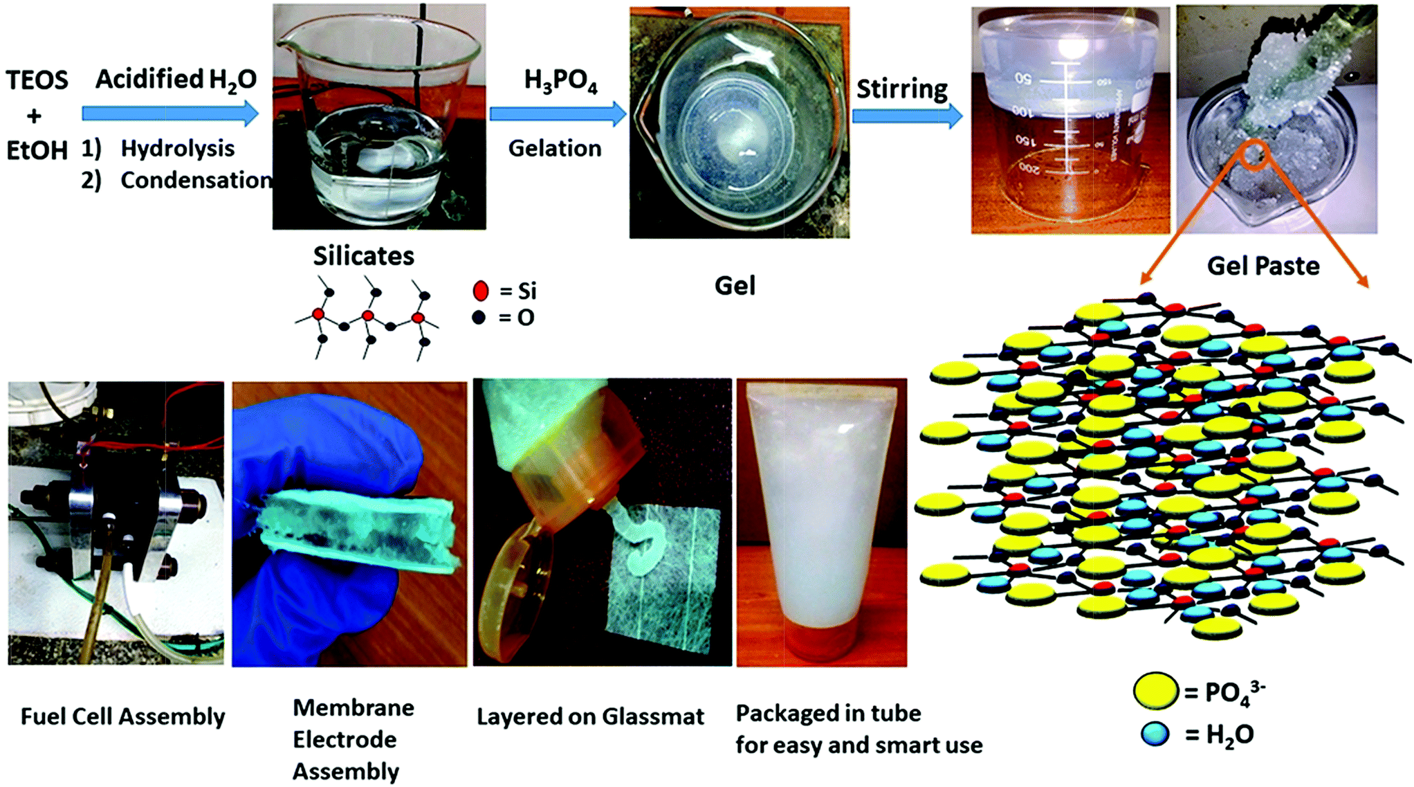 | ||
| Scheme 1 Schematic illustration of the gel paste formation with its 3D structure and its application as a fuel cell electrolyte. | ||
2. Experimental
2.1 Materials
Tetraethoxysilane Si(OC2H5)4 (Sigma-Aldrich), hydrochloric acid (GR Merck), orthophosphoric acid (GR Merck), ethanol, and a glassmat (Sainergy) were used.2.2. Preparation of the gel paste
The gel paste was prepared using a simple sol–gel synthesis route. Tetraethoxysilane (TEOS) was mixed with ethanol (EtOH) by stirring and was acidified, as well as hydrolysed, with the addition of water containing HCl. Orthophosphoric acid was added to the mixture under constant stirring. As this reaction is an exothermic reaction, orthophosphoric acid was added drop wise. A homogeneous gel like mixture was obtained after 50–60 minutes of stirring. The gel-like mixture was then dried at 80 °C in a vacuum oven to remove the ethanol. The ethanol-free gel was then heated with constant stirring using a glass rod in a heating mantle until a paste-like slurry was obtained. The P/Si ratios were varied by changing the amount of phosphoric acid. Fixing the TEOS content as Si, the orthophosphoric acid content was changed. The P/Si ratio was varied from 4 to 6. The different samples of the gel paste are termed as gel paste-i, where i denotes the P/Si ratio. A schematic representation of the gel paste formation is illustrated in Scheme 1.2.3. Preparation of the gel paste membrane
The gel paste slurry uniformly coated on both sides of a glass mat was used as an electrolyte. The gel paste was coated and compressed in such a way that the thickness of the layer became uniform throughout the membrane.2.4. Characterization and measurements
The structural analysis of proton conductive all inorganic gel pastes of different composition was performed using powder X-ray diffraction (PXRD), and Fourier-transform infrared (FTIR), Raman and 29Si, 31P and 1H nuclear magnetic resonance (NMR), and energy-dispersive X-ray (EDX) spectroscopies. PXRD analyses were performed using an Ultima III, (Rigaku, Japan) applying a 40 kV voltage, 30 mA current, and 1.2 kW of power from 10° to 60° in the 2θ range. The FTIR spectra were measured with a PerkinElmer FTIR spectrometer (FT-IR-8400S) using KBr pellets. The Raman analysis was performed using a JY Horiba LabRAM HR (λexc 532 nm) spectrometer within a wavenumber range of 100–1400 cm−1. Solution state 1H and 31P NMR spectra were recorded using a JEOL 400 MHz spectrometer at 161 MHz for 31P NMR and at 399 MHz for 1H NMR with d6-DMSO as the solvent. The solid state 29Si NMR spectra were also recorded using a JEOL 400 MHz spectrometer at 79 MHz.The morphological analysis was performed using scanning electron microscopy (SEM) and the corresponding EDX spectra. The surface morphology was observed using a JEOL JSM-6360 scanning electron microscope. The EDX analysis was performed using an FEI INSPECT F50 instrument. The thermal stability of the gel paste was measured by thermogravimetric analysis (TGA) using a PerkinElmer Pyris Diamond model with a 150 ml min−1 rate nitrogen flow with a heating rate of 10 °C min−1. The water uptake and acid uptake properties of the gel paste were calculated from the TGA analysis.
The temperature dependent proton conductivities of the gel paste coated glass mat membranes were determined by a two probe method using a Metrohm Autolab AUT84999 PGSTAT 302N potentiostat/galvanostat (Ecochemie, The Netherlands) over a frequency range of 1 Hz to 1 MHz with a sine wave amplitude of 10 mV. A constant voltage was supplied through the Autolab potentiostat. Gel pastes with different P/Si ratios were coated on both sides of a glass mat and sandwiched between two 0.785 cm2 area platinum electrodes. The distance between the two electrodes was 0.065 cm, i.e. the thickness of the gel coated glass mat. The proton conductivity of 88% H3PO4 was measured in an electrochemical cell, as described in the literature.23 A schematic illustration of the measurement of the conductivity of the gel paste is shown in the ESI (see Fig. S5 in the ESI†). A sinusoidal voltage signal from the Autolab potentiostat was applied across this platinum plate and gel paste membrane combination. The conductivity was calculated using the following formula:24
| σ = (L/A) × (1/R) (S cm−1) |
Fuel cell performance measurements
The fuel cell performance of the gel paste electrolyte was tested in a unit cell (Purchased from Sainergy Fuel Cell India Private Limited) with an active area of 10 cm2. The gel paste electrolyte was uniformly layered on both sides of the glass mat. The total electrolyte matrix was sandwiched between two commercially available carbon black platinum electrodes to form a membrane electrode assembly (MEA). These two electrodes were used as the anode and cathode. This MEA was placed between two channelized graphite grooves, where humidified hydrogen gas is in contact with the anode and oxygen is in contact with the cathode. Two stainless steel plates were placed on both sides as current collectors. Two heaters fitted with a PID temperature controller were placed on the top and bottom of the unit cell to maintain a particular temperature uniformly. Graphite gaskets were used for a good fit. The hydrogen and oxygen gas flow rates were maintained as 2 litres per minute and 1 litre per minute (LPM), respectively.3. Results & discussion
The steps of the gel paste formation and the structures of the silicate linkage and hydrogel paste are presented in Scheme 1. The synthesis of this all inorganic gel paste involves four steps: hydrolysis followed by condensation, gelation and drying. Gelation, an exothermic process, is accelerated with the addition of the orthophosphoric acid.25 Gelation time decreases upon an increase in the phosphate content. With an increase in the phosphoric acid content, i.e. the P/Si ratios, the mixture becomes more pasty and gelatinous. The gel is a solid–liquid phase mixture, where three dimensional crosslinked networks serve as the solid phase providing rigidity and hardness and the liquid is dispersed in the solid network as a discontinuous phase. In this gel paste, the phosphoric acid remains intact as the liquid phase, whereas the thermally stable three dimensional Si–O–Si network plays the role of the solid phase. The main interactions present here are weak van der Waals forces, –H bonding and dipole–dipole interactions. A large amount of phosphoric acid and water molecules are trapped in between the thermally stable Si–O–Si networks.3.1 Structural analysis
The structural features of the gel paste can be explained from the PXRD patterns. In the PXRD pattern shown in Fig. 1(a), no intense diffraction peaks can be observed, suggesting the absence of crystallinity and the highly amorphous nature of the substance.26,27 Interestingly, it is observed that an increase in the P/Si ratio from 4 to 6 causes a shifting of the peak to a lower value of 2θ. For gel paste-4, this peak arises at 2θ = 27.4°, for gel paste-5, it is at 2θ = 27.2°; for gel paste-6, a shift occurs resulting in a peak at 2θ = 26.9°. Upon an increase in the phosphoric acid content of the material, the powder pattern becomes more flattened indicating a more amorphous nature of the sample. In gel paste-6, the acid content is 6 times higher than the silica content, resulting in a more gelatinous and pasty nature, which can also be confirmed from the PXRD patterns. The broad diffraction peaks are due to the amorphous structure of the gel paste. It has been reported in literature28 that crystallinity mainly arises at a higher temperature, but the gel paste remained amorphous up to 200 °C.29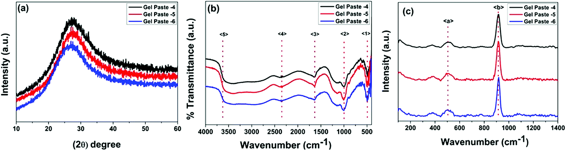 | ||
| Fig. 1 PXRD patterns, and FTIR and Raman spectra of the gel paste with different P/Si ratios. (a) The PXRD patterns, (b) the FTIR spectra and (c) the Raman spectra. | ||
FTIR spectra in the range of 500–4000 cm−1 for gel pastes with different P/Si ratios are shown in Fig. 1(b). The absorption peak at 〈1〉 at around 480 cm−1 is due to Si–O–Si rocking vibrations.30 The intense peak 〈2〉 at 1008 cm−1 is due to the stretching vibration of Si–O, which is assigned to the Si–O–Si linkages.12,31 The characteristic peaks in the range of 950 cm−1 to 1050 cm−1 are assigned to the Si–O–Si and P–O, and P–OH linkages of the gel paste.12,28,30,32–35 The symmetric modes of PO and O–P–O are mainly observed in the range of 950–1200 cm−1, which confirms that the silica network is doped with phosphate units.12,28,36 The peak 〈3〉 at 1693 cm−1 is assigned to –H bonded or adsorbed molecular water and confirms the presence of –OH groups in the cavity of the pores.28,30,36–40 The absorption peak 〈4〉 at 2310 cm−1 is the characteristic vibration of P–O–H, which confirms the presence of phosphate linkages in the gel paste.12 The broad absorption band 〈5〉 at 3360 cm−1 can be mainly assigned to Si–O–H and P–O–H arising from the –H bonding with adsorbed water molecules. In the gel paste, a large amount of water molecules are trapped in the cavity, which form –H bonds with the oxygen atoms of the Si–O and P–O linkages. The water molecules show peaks at around 3950 cm−1. All of the absorption peaks are evident for all three paste compositions (P/Si = 4, 5, 6). The data concludes that the gel is a large network of Si–O–Si, Si–O–H, and P–O–H bonds, where water molecules and orthophosphoric acid are trapped.
The Raman spectra of gel pastes with different compositions are shown in Fig. 1(c). Two peaks at 511 cm−1 and 915 cm−1 are observed in Fig. 1(c). McMillan et al.41 have shown that in the low frequency region, vibration bands in the region of 400–700 cm−1 are due to the presence of bridging oxygen or Si–O–Si linkages and these linkages confirm the presence of more polymerized silicates than orthosilicates. A broad peak 〈a〉 starting at 430 cm−1 and ending at 570 cm−1 can be observed in the Raman spectrum. The peak is at a maximum at 511 cm−1 and is a characteristic peak of silicates with almost all four oxygens bridged. A low intensity hump is obtained rather than an intense peak, mainly due to the defects in the structure and defects arising due to hydrogen bonding and other van der Waals force of attraction arising in the cavities. The other intense peak at around 915 cm−1 is due to the P–OH symmetric stretching of the PO43− and the out of plane –OH bending vibrations.42–44 By varying the P/Si ratio from 4 to 6, the peak intensity increases. As the sample is heated only at 100 °C, no Si–O–P bonds can be formed, and H3PO4 remains in a hydrogen bonded state. The PO43− units are hydrogen bonded in the cavities.
The liquid-like mobility in the solid silicate network was confirmed using three different types of NMR analysis. The 1H NMR, 31P NMR and 29Si NMR spectra of gel paste-5 are depicted in Fig. 2 and 3(a) and (b), respectively. The corresponding 1H NMR, 31P NMR and 29Si NMR spectra of gel paste-4 and gel paste-6 are shown in the ESI (see Fig. S1, S2 and S3,† respectively). The sharp and intense resonance peak referenced to the TMS standard at δ = 7.392 for gel paste-4 (see Fig. S1(a)†), δ = 5.493 for gel paste-5 and δ = 7.055 (see Fig. S1(b)†) for gel paste-6 are assigned to the POH groups involved in the weak hydrogen bonding.45,46 The deviation of the δ value of gel paste-5 (δ = 5.493) from that of gel paste-4 (δ = 7.392) can be attributed to the variation in the extent of the water content. With an increase in the acid content (P/Si 4 to 5), the gel becomes more gelatinous and pasty in nature and absorbs more water leading to upfield shifting. In gel paste-6, the δ value further increases due to an over flooding of the cavities and the presence of external surface water, which is also clearly observable from the SEM images.47 The small intense resonance peaks at δ = 1.06 and δ = 3.8 can be assigned to the methyl (CH3CH2O–) and methylene (CH3CH2O–) parts of the ethoxy group, respectively.45 The small and narrow shape indicates that the ethoxy group undergoes high frequency pseudo-isotropic dynamics. Another sharp and intense peak at δ = 2.46 is due to the use of deuterated dimethyl sulfoxide (C2D6OS) as the solvent. In the 31P NMR spectrum of gel paste-5, shown in Fig. 3(a), the sharp and intense peak observed at 0 ppm (Qo), can be attributed to the isolated orthophosphoric acid.21,48–50 The absence of any other peaks in the 31P NMR spectrum confirms the absence of condensed phosphoric acid, i.e. phosphoric acid with bridging oxygens such as Si–O–P or P–O–P. The absence of any Q1, Q2, Q3 and Q4 peaks eliminates the probability of the presence of singly, doubly, triply and fully coordinated P atoms. We prepared gel pastes from TEOS and H3PO4 at room temperature. The results confirm that for all of the gel pastes, the phosphoric acid remains in a pure and isolated form; there is no solid condensation bonding. It also confirms the absence of Si–O–P and P–O–P bonds. Similar features were also observed for gel paste-4 and 6 (see Fig. S2(a) and (b),† respectively). The solid state 29Si NMR spectrum of gel paste-5 shown in Fig. 3(b) shows one resonance peak at −112 ppm referenced to the standard TMS (using solid tetrakis(trimethylsilyl)silane (TTSS) at −9.8 ppm as a secondary reference) confirming the four-coordination of the silica to the bridging oxygen in the tetrahedral silicate networks. A chemical shift of −115 ppm is the extreme downfield of the chemical shift range reported for [SiO4] groups.22 Only pure zeolitic silica has a chemical shift more downfield than −110 ppm, which is average for Q4 groupings of silicate minerals. This confirms that the Si in the gel paste is in the pure zeolitic form. The 29Si NMR spectra of gel pastes-4 and 6 (Fig. S3(a) and (b)†) show resonance peaks at −111 ppm for gel paste-4 and -110 ppm for gel paste-6, which are characteristic of four coordinated silica. The absence of any other intense resonance peaks in the more downfield region eliminates the chances of the presence of six coordinated silica.
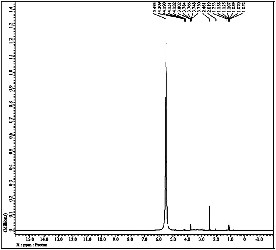 | ||
| Fig. 2 Solution state 1H NMR studies of gel paste-5 in d6-DMSO, referenced to TMS. | ||
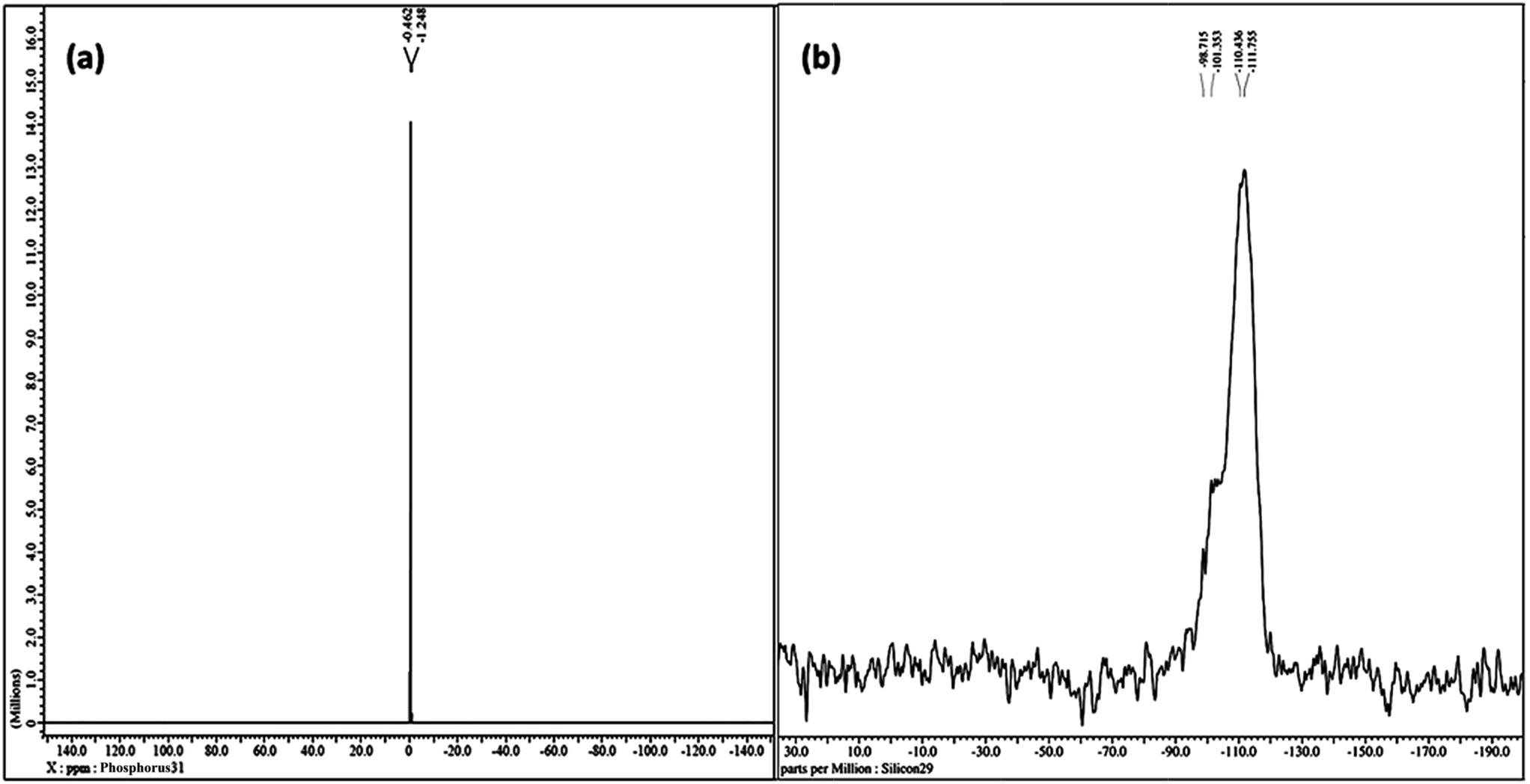 | ||
| Fig. 3 NMR studies of gel paste-5. (a) The solution state 31P NMR spectrum in d6-DMSO and (b) the solid state 29Si NMR spectrum. | ||
The presence of four coordinated silica, as evidenced from 29Si NMR, and isolated, non-bridged P, as evidenced from 31P NMR and weakly hydrogen bonded POH, as evidenced from 1H NMR, confirms that in the gel paste, H3PO4 is in a hydrogen bonded state within a Si–O–Si cage.
3.2 Thermogravimetric analysis (TGA)
The TGA of the gel pastes is shown in Fig. 4(a). In all cases (gel pastes-4 to 6), the first loss, occurring at around 100 to 150 °C, can be ascribed to the loss of physically adsorbed water and the evaporation of trapped solvents (ethanol and water). There is another weight loss at around 200 °C, which can be attributed to the dehydration of the phosphoric acid moiety.12,48,50 The dehydration of phosphoric acid leads to the formation of pyrophosphoric acid and triphosphoric acid.51–53 These results signify the good characteristics of the gel paste for trapping water and phosphoric acid up to 200 °C, which makes it a medium temperature range solid state proton conductor. The mass loss above 250 to 400 °C is mainly due to the composition of the residue moieties present in the gel.30,48 The change in the slope of the TGA curves at 550 °C and the associated weight loss above 550 °C for higher P/Si ratios (4, 5, 6), especially for gel paste-5 and gel paste-6, are probably due to the decomposition of species (pyrophosphoric acid and triphosphoric acid) obtained from the polycondensation of the orthophosphoric acid unit.35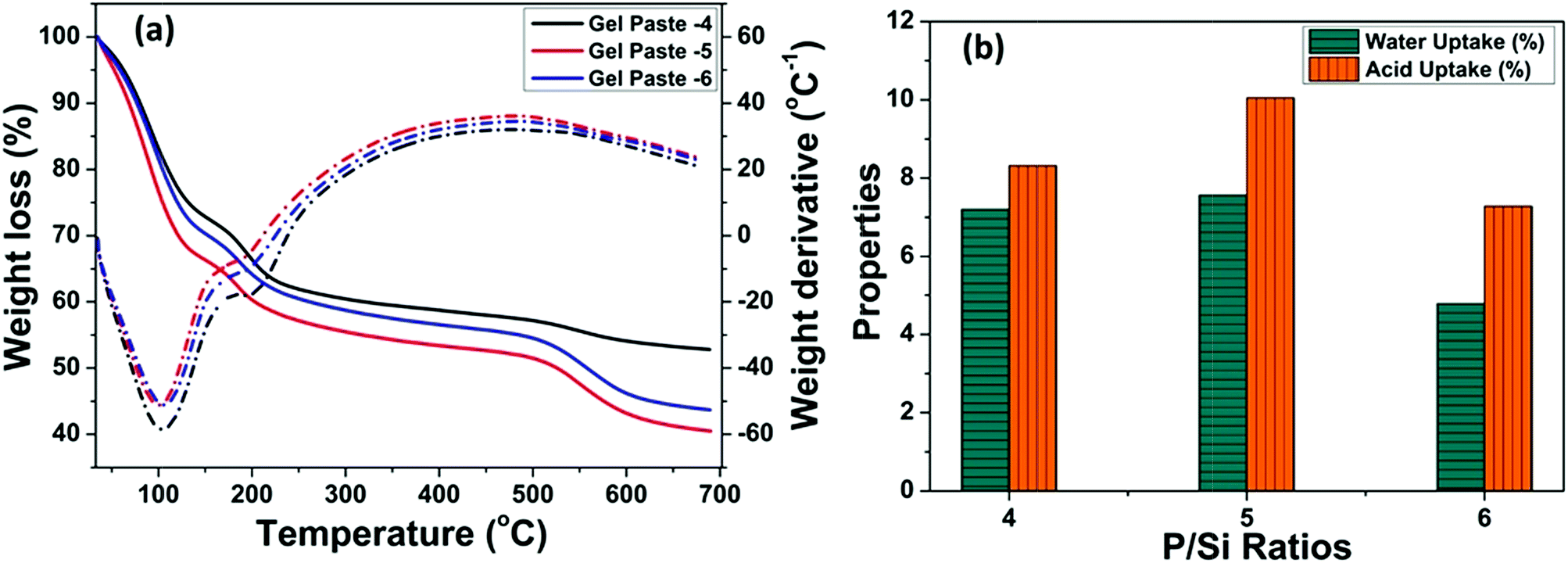 | ||
| Fig. 4 (a) Thermogravimetric analysis of gel pastes of different compositions, and (b) water and acid uptake properties evaluated from the TGA plot. | ||
Interestingly, at any temperature, the maximum weight loss was observed for gel paste-5. The values of water uptake and acid uptake for different P/Si ratios were evaluated from the TG analysis and are shown in Fig. 4(b). Comparative analysis of the TGA of gel paste-4, 5 and 6 reveals that gel paste-5 contains a greater amount of trapped acid and adsorbed water. As a result, gel paste-5 exhibits higher proton conductivity values and better fuel cell performance compared to gel paste-6. This will be discussed below in Sections 3.4 and 3.5. The evaluated water and acid uptake values from the TG analysis have a good correlation with the composition of the gel paste. The calculated water uptake values of gel pastes-4, 5, 6 are 7.19%, 7.56% and 4.79%, respectively, whereas the acid uptake values are 8.31%, 10.05% and 7.28%, respectively.
3.3. Morphological analysis
The SEM images of the gel pastes (with different P/Si ratios) before and after the fuel cell experiments are shown in Fig. 5. From the SEM images, it is evident that the material is highly amorphous and has paste-like features. From the images it is also clear that the gel paste is more amorphous before the experiments. During the experiments the trapped water and orthophosphoric acid are used up and the gel becomes dry in nature. In particular, for P/Si ratio 6, the signature of macropores, excess surface water and orthophosphoric acid are observed (see Fig. 5c-1) after the experiments and the electrolyte sample still remains paste-like in nature. On the contrary, a distinct structural transformation during the experiments was observed for gel paste-4 and gel paste-5 (Fig. 5a-1, 5a-2, 5b-1 and 5b-2) and a transformation of paste to particle-like structure occurred as the electrolyte was used in the fuel cell experiments.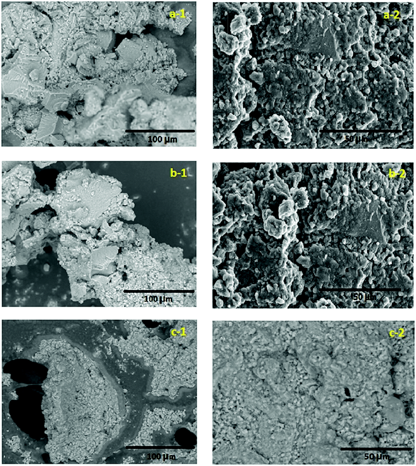 | ||
| Fig. 5 SEM images of the gel pastes at different P/Si ratios where (a-1 and a-2) represent P/Si = 4 before and after the fuel cell experiments, respectively. Similarly (b-1 and b-2) represent P/Si = 5 before and after the experiments and (c-1 and c-2) represent P/Si = 6 before and after the experiments. | ||
EDX analysis of the three gel paste samples confirmed the compositions of P and Si in the samples (see Fig. S3†). The mole ratio obtained from the EDX analysis has good correlation with the experimental mole ratios. From the EDX analysis, the calculated values of the P/Si ratios with respect to weight percentages are 3.646, 4.591, and 6.081 for gel pastes-4, 5 and 6, respectively, and with respect to the atomic percentage are 3.307, 4.165 and 5.520, respectively.
3.4 Proton conductivity
The temperature dependent proton conductivity measurements of the gel pastes-4, 5 and 6 and H3PO4 used in the PAFCs are shown in Fig. 6(a). The corresponding Nyquist plots at 160 °C are shown in Fig. 6(b). | ||
| Fig. 6 (a) Temperature dependent proton conductivity of different gel pastes compared with 88% phosphoric acid and Nafion 115 at ambient pressure; the Nafion 112 and 100% H3PO4 data have been incorporated from literature.22,56 The solid symbols represent the experimental data from this work, and the open symbols represent the data from literature. (b) The corresponding Nyquist plots at 160 °C of three gel pastes and 88% phosphoric acid and (c) shows the fitting circuit of the Nyquist plot. | ||
The Randles–Ershler model54 was found to fit perfectly with the experimental data. The circuit is depicted in Fig. 6(c). In this model, RΩ and Rct represent the ohmic resistance and charge transfer resistance, respectively, and Ws represents the finite-length Warburg impedance, arising due to the diffusion of protons through pores.23,54,55 The conventional double layer capacitance is replaced by a constant phase element (CPE) because of the non-uniform distribution of the capacitance caused by double layer charging.23,54
All the conductivity values are compared with two different literatures; one with 100% H3PO4 from crystal22 another with Nafion 112 at fully hydrated state.56 Upon an increase in the temperature, the proton conductivity was observed to increase for the gel pastes. The gel pastes gave the best results at 160 °C and then showed a decrease and can sustained up to 180 °C. Among all the different cases, the gel paste with the P/Si = 5 ratio was observed to exhibit the best proton conductivity values over the entire range of temperatures from 30–180 °C. The proton conductivity values and the variation in the proton conductivity values upon changing the P/Si ratios, both reached a maximum at 160 °C and the increase in the P/Si ratio from 5 to 6 caused a decrease in the proton conductivity due to the presence of less orthophosphoric acid and more pyro- and triphosphoric acids (as evidenced from the TG analysis). Here, the conductivity of the gel paste is compared with the conductivity of the conventional phosphoric acid fuel cell (PAFC) and the commercially purchased Nafion membrane. In conventional PAFCs, an 88% orthophosphoric acid soaked glass mat is used for the conductivity measurements. The gel paste shows better conductivity than the 88% phosphoric acid soaked glass mat used in PAFCs. In PAFCs, upon an increase in the temperature, acid leaches out from the glass mat, whereas in the gel paste, the acid molecules are trapped in the thermally stable Si–O–Si network. The commercially purchased Nafion membranes were soaked in 88% orthophosphoric acid for three days and tested in conductivity measurements. The conductivities of all three of the gel pastes were higher than those of the Nafion 115 and Nafion 112 membranes at 100% relative humidity. The maximum operating temperature of the Nafion membrane is 90 °C, but it showed the best result at 70 °C. At 90 °C, the melting of the Nafion membrane begins to occur.
It is known that the proton conductivity of phosphoric acid depends on the formation of a contact ion pair (H4PO4+/H2PO4−), and the electrostatic interaction of the associated electric dipole moments within the unrelaxed solvent environment with transiently short hydrogen bonds.23,56 The proton transportation follows the jumping of the proton through the Grotthuss mechanism.58–60 In the gel paste, the phosphoric acid remains trapped inside the 3D Si–O–Si network via hydrogen bonding. The solvent environments in normal phosphoric acid solution and in the gel paste are wildly different since the Si–O–Si network provides a facile proton conductive passage and water trapped in the cavities plays a major role in proton conduction.23,57,61
3.5 Fuel cell performance using gel paste electrolyte: determination of the optimum P to Si ratio
The temperature dependent fuel cell performance of the gel paste with a P to Si ratio = 5 at a humidifier temperature (TH) of 70 °C is shown in Fig. 7(a). Over a temperature range of 110 to 180 °C, the fuel cell performs the best at 160 °C, following the same trend as that of the proton conductivity of the electrolyte. A maximum current density of >1 A cm−2 and a power density of >210 mW cm−2 were achieved at 160 °C. The performance is less temperature sensitive in the higher temperature region.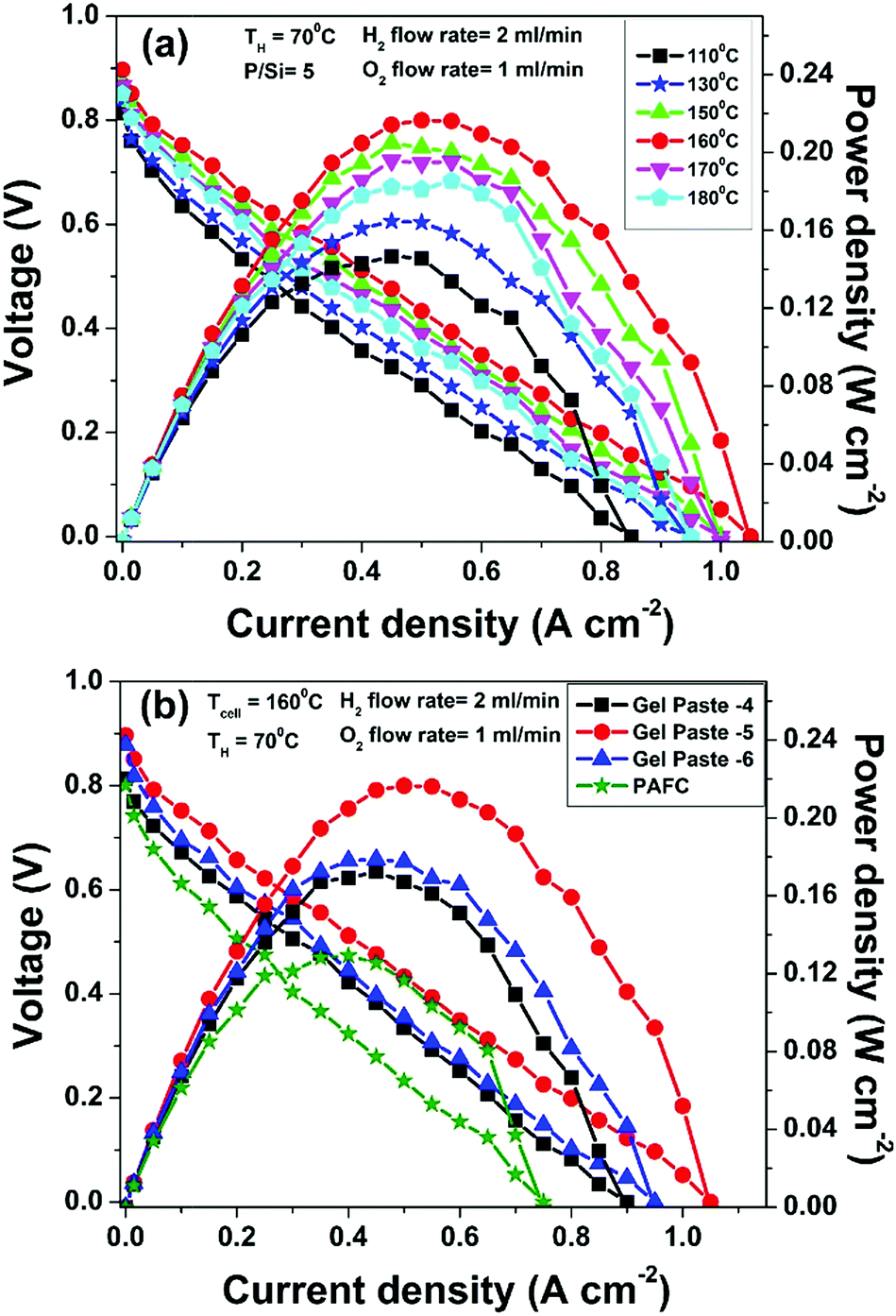 | ||
| Fig. 7 (a) Temperature dependent fuel cell performance of the gel paste-5 electrolyte at a fixed humidifier temperature (TH) of 70 °C and H2 flow rate = 2 LPM, O2 flow rate = 1 LPM. (b) A comparison between the fuel cell performance of gel pastes of different P/Si ratios (at a humidifier temperature (TH) of 70 °C, cell temperature (TCell) of 160 °C and H2 flow rate = 2 LPM, O2 flow rate = 1 LPM) and the phosphoric acid fuel cell data. | ||
The comparative fuel cell performance (voltage and power versus current density) of the different gel paste electrolytes with P/Si ratios of 4, 5 and 6 and a conventional PAFC at a 160 °C operating temperature is illustrated in Fig. 7(b). Among the three electrolytes, the gel paste with a P/Si ratio of five offers the best performance (maximum power density > 210 mW cm−2). At a cell temperature (TCell) of 160 °C and humidifier temperature (TH) of 70 °C, the variation in the P/Si ratio from 4 to 5 increases the peak power generation by 25.49% and the corresponding current density is also shifted towards a higher value. In comparison with the PAFC, 67.51% peak power enhancement was achieved using the gel paste electrolyte with a P/Si ratio of 5. Also, it may be inferred from the voltage versus current density plots, that among all of the electrolytes, gel paste-5 exhibits the highest value (1.05 A cm−2) of threshold current density (at which the voltage becomes zero). The result follows the same trend as that of the proton conductivity data shown in Fig. 6.
The fuel cell durability plot of the different gel paste (coated glass mat matrices) electrolytes is shown in Fig. 8. In order to address the endurance of electrolyte under load (usually referred to as a degradation rate), the gel paste electrolyte was placed between the two electrodes and the fuel cell was operated at 160 °C under a fixed load current density of 50 mA cm−2 for 29 hours and the variation of voltage over time was recorded and plotted, as shown in Fig. 7. Among the different electrolytes, the gel paste with a P/Si ratio of 5 was observed to offer the best durability.
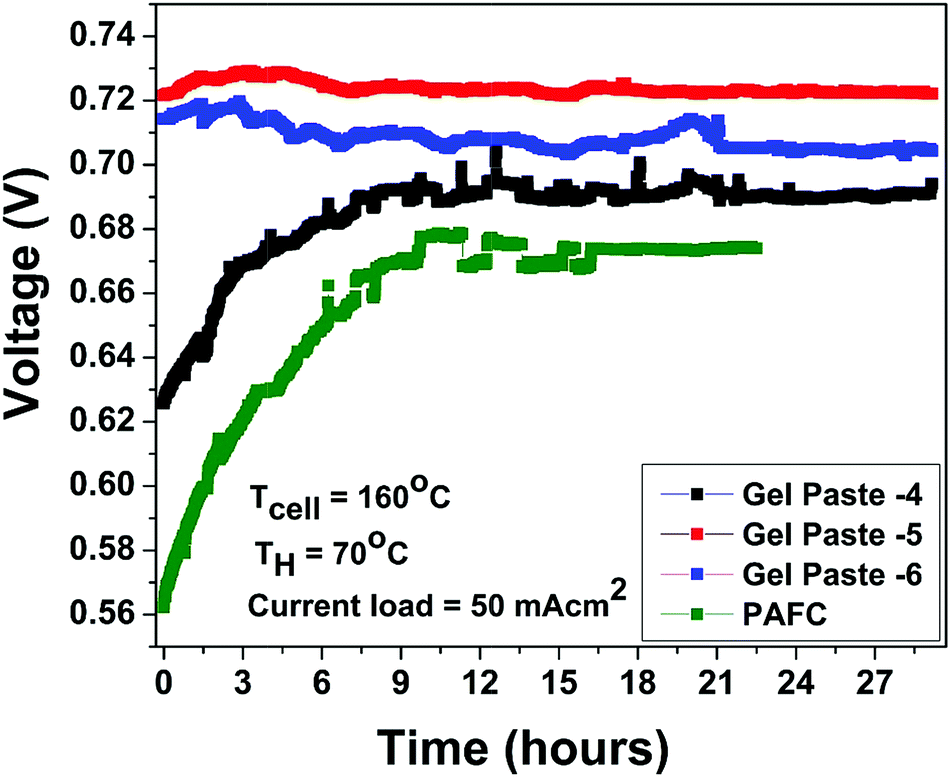 | ||
| Fig. 8 Stability plot of gel pastes with different P/Si ratios and the PAFC at a humidifier temperature (TH) of 70 °C and cell temperature (TCell) of 160 °C with a constant current load of 50 mA cm2. | ||
The voltage efficiency is defined as 
The theoretical electromotive force (EMF) is 1.2 volts. Two different values of voltage efficiency are calculated: one based on the open circuit voltage (OCV) and another based on the voltage corresponding to the peak power density. Among all the different electrolytes, gel paste-5 had the maximum values of threshold load current, maximum peak power density and voltage efficiencies. Although the maximum operating temperature of the fuel cell with gel paste-5 electrolyte is 180 °C, the best performance was observed at 160 °C.
Table 1 summarizes the performance of all of the inorganic gel paste electrolytes for application in fuel cells. The quantitative parameters include maximum operating temperature, threshold load current, maximum peak power density, voltage efficiency and durability in hours. The threshold load current is the maximum sustainable current density value of the cell, i.e. the specific current density of the cell at zero voltage. The maximum peak power density is another valuable parameter of a fuel cell. It is the power density that actually determines the strength of the fuel cell.
| Matrices | Maximum operating temperature (°C) | Threshold load current (mA cm−2) | Maximum peak power density (mW cm−2) | Voltage efficiency (%) (OCV) | Voltage efficiency at Pmax (%) | Durability (hours) | Ref. |
|---|---|---|---|---|---|---|---|
| Phosphoric acid 85% (cell area 0.5 cm2) | 226 | 303 | 59 | 85.7 | 32.9 | 23 | 4 |
| SiPOH (cell area 0.5 cm2) | 226 | 966 | 184 | 85.4 | 33.8 | 23 | 4 |
| Stabilised SiPOH gel | 154 | 1100 | 200 | 85.83 | 33.33 | 24 | 22 |
| Fe(III) phytate metallogel | 130 | 1.2 (at 80 °C) | 0.55 | 72.5 | 48.24 | — | 17 |
| Gel paste-4 | 180 | 900 | 172 | 67.83 | 31.91 | 29 | This work |
| Gel paste-5 | 180 | 1050 | 216 | 74.75 | 36.083 | 29 | This work |
| Gel paste-6 | 180 | 950 | 178 | 73.25 | 33.083 | 29 | This work |
| PAFC | 160 | 750 | 129 | 66.75 | 26.91 | 22.5 | This work |
In order to reveal the superiority of the performance of gel paste-5, the results of the present work were compared with reported data, as shown in Table 1.4,17,22 The literature on gel electrolytes including fuel cell performance is scant. Some of the literature data on gel electrolytes showing fuel cell performance are compared here. H. B. Aiyappa et al.17 synthesized a proton conducting metallogel based on metal organic materials (MOMs), constituting a phosphate ester based ligand immobilized via gelation with Fe3+ ions in DMF and used them to perform fuel cell operations. A power density of 0.55 mW cm−2 at 80 °C and a high proton conductivity value of 2.4 × 10⁻² S cm−1 at 120 °C were achieved with these MOMs. Ansari et al.4 synthesized an anhydrous modified H3PO4 liquid electrolyte embedded with a silica network [Si(PO4H)2] that showed a power density of 184 mW cm−2 at 226 °C. The all inorganic fiberglass reinforced gel membrane made recently by Ansari et al.22 achieved a maximum current of >1 A cm−2, a power density of 200 mW cm−2 at 154 °C and could be used for up to 24 hours with a load of 50 mAcm−2. Gel paste 5 offers a threshold load current of >1 A cm−2 and a peak power density of 216 mW cm−2 at 160 °C. The maximum power density, which actually determines the strength of a fuel cell, achieved in this study was observed for gel paste-5. It also showed the maximum durability of 29 hours at a 50 mA cm−2 current load.
Fig. 9(a) summarizes the effect of the P/Si ratio on the proton conductivity and performance of the fuel cell with the gel paste electrolyte. The results show that the proton conductivity, peak power density and corresponding current density, and threshold load current are maximized at the optimum P/Si ratio value of 5. For commercial, easy and smart use purposes, gel paste-5 was stored in a tube and used as per requirement. To check the performance of the gel paste stored in the tube, the proton conductivity was measured. Fig. 9(b) shows the proton conductivity value of gel paste-5 with respect to time. It also gives a clear idea of how long the gel paste can be used for good performance or in commercial language how long it can suitably be used before expiry. Around 8%, 18.91%, 30.23% and 60.25% decay in the proton conductivity was observed after 6 months, 10 months, 14 months and 20 months, respectively.
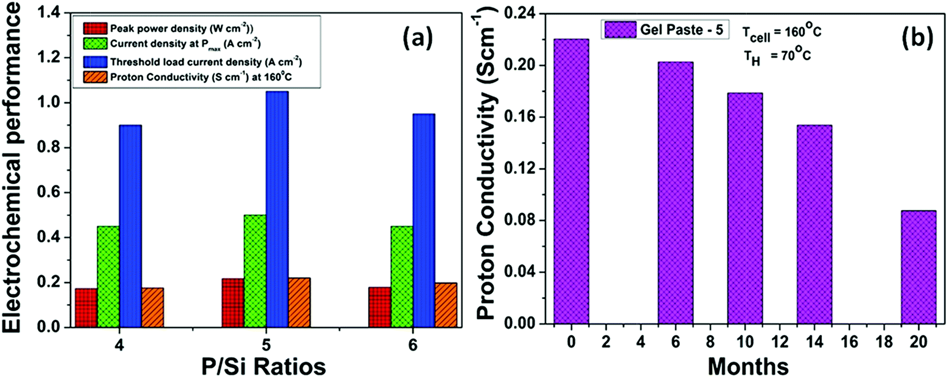 | ||
| Fig. 9 (a) Electrochemical performance summary of gel paste-5, (b) time dependent stability with respect to the proton conductivity of gel paste-5 preserved in a tube for commercial use purpose at a humidifier temperature (TH) of 70 °C and a cell temperature (TCell) of 160 °C. | ||
4. Optimum P/Si ratio and proposed structure of the gel paste
As discussed above in Section 3, the gel paste can be considered as silica gel with H3PO4 trapped in the solid pores or cavities of the Si–O–Si networks or adsorbed on the SiO2 surface. The proposed large network of gel paste consisting of Si–O–Si, Si–O–H, and P–O–H (as evidenced from FTIR and NMR analysis), where water molecules and orthophosphoric acid are trapped through hydrogen bonding, is depicted in Scheme 1. Upon an increase in the P/Si ratio, the increase in the amount of trapped H3PO4 makes the gels pastier in nature. H3PO4, being hygroscopic in nature, absorbs water, thus with an increase in the P/Si ratio, the absorbed water content also increases. Both H3PO4 and H2O are trapped in the cavities of the thermally stable Si–O–Si network. With an increase in the P/Si ratio the 3D structure of the Si–O–Si network accommodates a greater number of phosphoric acid and associated water molecules, which helps in conducting protons through the Grotthuss mechanism.57–59 However, depending on the size of the energetically stable Si–O–Si network unit, there must exist an upper limit of phosphoric acid molecules that could be accommodated. Whenever this limit is crossed (as the P/Si ratio increases beyond 5), the excess acid does not take part in conducting protons in the network, but instead leaches out to the surface, as observed in the SEM measurements. Accordingly, beyond the optimum P/Si ratio value, the values of the acid uptake, water uptake, and proton conductivity start to reduce.5. Conclusion
A portable, ready-to-use, smart, phosphorous and silica-based three dimensional, highly proton conductive inorganic gel paste electrolyte, that can retain its physical (gel paste) form and properties over several months, has been synthesized, characterized and tested in a fuel cell. The gel pastes, consisting of a 3D network of Si–O–Si and P–O–H bonds, where water molecules and orthophosphoric acid are trapped through hydrogen bonding, were synthesized using a sol–gel route by varying the P/Si ratio and were characterized using PXRD, TGA, SEM and FTIR, NMR, EDX and Raman spectroscopies. It was revealed that the gel paste with the optimum P/Si ratio of 5 had the best proton conductivity, acid and water uptake values. The proton conductivity of the same gel paste exceeds that of Nafion over the broad temperature range of 50 to 180 °C. The fuel cell assembled with gel paste-5 coated on a glass mat, operating at a temperature of 160 °C, produced a maximum current density of 1050 mA cm−2, a power density of 216 mW cm−2 and could be used for up to 29 hours. The same assembly offers almost three times more power density compared to that of a phosphoric acid fuel cell at an operating temperature of 160 °C. It is proposed that depending on the size of the energetically stable Si–O–Si network unit of the gel paste, that there exists an upper limit of phosphoric acid molecules that could be accommodated, which in turn determines the optimum P/Si ratio value that leads to the maximized performance of the gel paste electrolyte. Beyond a P/Si ratio value of 5, the excess acid no longer takes place in conducting protons in the network, but instead leaches out to the surface, as evidenced from SEM analysis. Theoretical studies based on density functional theory (DFT) or molecular simulation of such a system may confirm the proposed structure of the gel paste.Conflicts of interest
There is no conflict to declare.Acknowledgements
One of the authors P. Ghosh, acknowledges Department of Science and Technology, Ministry of Science and Technology, India, (DST WOSA, File No. SR/WOS-A/ET-40/2016), for her research fellowship. The financial assistance from the University Grants Commission (UGC), India, (File No. 41-369/2012(SR)) and Defence Research and Development Organization (NMRL-DRDO) are gratefully acknowledged. The NMR Research Center (NRC), IISC Bangalore is gratefully acknowledged for the 29Si NMR facilities.Notes and references
- X. Lu, Y. Zeng, M. Yu, T. Zhai, C. Liang, S. Xie, M.-S. Balogun and Y. Tong, Adv. Mater., 2014, 26, 3148–3155 CrossRef PubMed.
- X. Wang, X. Lu, B. Liu, D. Chen, Y. Tong and G. Shen, Adv. Mater., 2014, 26, 4763–4782 CrossRef PubMed.
- H. Nishide and K. Oyaizu, Science, 2008, 319, 737–738 CrossRef PubMed.
- Y. Ansari, T. G. Tucker and C. A. Angell, J. Power Sources, 2013, 237, 47–51 CrossRef.
- S. Das, R. Gulotty, A. V. Sumant and A. Roelofs, Nano Lett., 2014, 14, 2861–2866 CrossRef PubMed.
- B. G. Choi, M. Yang, W. H. Hong, J. W. Choi and Y. S. Huh, ACS Nano, 2012, 6, 4020–4028 CrossRef PubMed.
- Y. Xu, Z. Lin, X. Huang, Y. Liu, Y. Huang and X. Duan, ACS Nano, 2013, 7, 4042–4049 CrossRef PubMed.
- L. Yao and S. Krause, Macromolecules, 2003, 36, 2055–2065 CrossRef.
- G.-P. Hao, F. Hippauf, M. Oschatz, F. M. Wisser, A. Leifert, W. Nickel, N. Mohamed-Noriega, Z. Zheng and S. Kaskel, ACS Nano, 2014, 8, 7138–7146 CrossRef PubMed.
- Y. Shi, L. Peng, Y. Ding, Y. Zhao and G. Yu, Chem. Soc. Rev., 2015, 44, 6684–6696 RSC.
- Y. G. Jin, S. Z. Qiao, Z. P. Xu, Z. Yan, Y. Huang, J. C. Diniz da Costa and G. Q. Lu, J. Mater. Chem., 2009, 19, 2363–2372 RSC.
- H.-J. Lee, J.-H. Kim, J.-H. Won, J.-M. Lim, Y. T. Hong and S.-Y. Lee, ACS Appl. Mater. Interfaces, 2013, 5, 5034–5043 CrossRef PubMed.
- M. Li and K. Scott, Electrochim. Acta, 2010, 55, 2123–2128 CrossRef.
- L. E. Shmukler, N. Van Thuc, Y. A. Fadeeva and L. P. Safonova, J. Polym. Res., 2012, 19, 9770 CrossRef.
- L. E. Shmukler, N. Van Thuc and L. P. Safonova, Ionics, 2013, 19, 701–707 CrossRef.
- L. E. Shmukler, N. Van Thuc, Y. A. Fadeeva and L. P. Safonova, J. Appl. Polym. Sci., 2014, 131, 40674 CrossRef.
- H. B. Aiyappa, S. Saha, P. Wadge, R. Banerjee and S. Kurungot, Chem. Sci., 2015, 6, 603–607 RSC.
- K. Kargupta, S. Saha, D. Banerjee, M. Seal and S. Ganguly, J. Fuel Chem. Technol., 2012, 40, 707–713 CrossRef.
- Q. Deng, R. B. Moore and K. A. Mauritz, J. Appl. Polym. Sci., 1998, 68, 747–763 CrossRef.
- K. A. Mauritz and J. T. Payne, J. Membr. Sci., 2000, 168, 39–51 CrossRef.
- A. Matsuda, T. Kanzaki, M. Tatsumisago and T. Minami, Solid State Ionics, 2001, 145, 161–166 CrossRef.
- Y. Ansari, T. G. Tucker, W. Huang, I. S. Klein, S. Y. Lee, J. L. Yarger and C. A. Angell, J. Power Sources, 2016, 303, 142–149 CrossRef.
- T. Paul, D. Banerjee and K. Kargupta, Ionics, 2015, 21, 2583–2590 CrossRef.
- P. Ngamsantivongsa, H.-L. Lin and T. L. Yu, J. Polym. Res., 2016, 23, 22 CrossRef.
- M. Yamane, S. Inoue and A. Yasumori, J. Non-Cryst. Solids, 1984, 63, 13–21 CrossRef.
- S. J. Huang, H. K. Lee and W. H. Kang, Bull. Korean Chem. Soc., 2005, 26, 241–247 CrossRef.
- J.-M. Lim, J.-H. Won, H.-J. Lee, Y. T. Hong, M.-S. Lee, C. H. Ko and S.-Y. Lee, J. Mater. Chem., 2012, 22, 18550–18557 RSC.
- A. M. Elnahrawy and A. I. Ali, New J. Glass Ceram., 2014, 4, 42–47 CrossRef.
- K. Hirata, A. Matsuda, T. Hirata, M. Tatsumisago and T. Minami, J. Sol-Gel Sci. Technol., 2000, 17, 61–69 CrossRef.
- L. Todan, C. Andronescu, D. M. Vuluga, D. C. Culita and M. Zaharescu, J. Therm. Anal. Calorim., 2013, 114, 91–99 CrossRef.
- P. Ghosh, D. Halder, S. Ganguly, D. Banerjee and K. Kargupta, Int. J. Plast. Technol., 2014, 18, 403–408 CrossRef.
- A. Matsuda, N. Nakamoto, K. Tadanaga, T. Minami and M. Tatsumisago, Solid State Ionics, 2006, 177, 2437–2441 CrossRef.
- A. Matsuda, T. Kanzaki, Y. Kotani, M. Tatsumisago and T. Minami, Solid State Ionics, 2001, 139, 113–119 CrossRef.
- L. Todan, E. M. Anghel, P. Osiceanu, R. V. F. Turcu, I. Atkinson, S. Simon and M. Zaharescu, J. Mol. Struct., 2015, 1086, 161–171 CrossRef.
- A. Aronne, M. Turco, G. Bagnasco, P. Pernice, M. Di Serio, N. J. Clayden, E. Marenna and E. Fanelli, Chem. Mater., 2005, 17, 2081–2090 CrossRef.
- D. Carta, D. M. Pickup, J. C. Knowles, M. E. Smith and R. J. Newport, J. Mater. Chem., 2005, 15, 2134–2140 RSC.
- A. M. Efimov and V. G. Pogareva, Chem. Geol., 2006, 229, 198–217 CrossRef.
- C. T. Johnston, G. Sposito and C. Erickson, Clays Clay Miner., 1992, 40, 722–730 CrossRef.
- H. Aguiar, J. Serra, P. Gonzales and B. Leon, J. Non-Cryst. Solids, 2009, 355, 475–480 CrossRef.
- M. Prokopowicz, Acta Biomater., 2009, 5, 193–207 CrossRef PubMed.
- P. McMillan, Am. Mineral., 1984, 69, 622–644 Search PubMed.
- B. O. Fowler, M. Markovic and W. E. Brown, Chem. Mater., 1993, 5, 1417–1423 CrossRef.
- M. Cherif, A. Mgaidi, N. Ammar, G. Vallée and W. Fürst, J. Solution Chem., 2000, 29, 255–269 CrossRef.
- W. W. Rudolph, Dalton Trans., 2010, 39, 9642–9653 RSC.
- N. J. Clayden, A. Aronne, S. Esposito and P. Pernice, J. Non-Cryst. Solids, 2004, 345–346, 601–604 CrossRef.
- R. M. Wenslow and K. T. Mueller, J. Phys. Chem. B, 1998, 102, 9033–9038 CrossRef.
- Y. Aihara, A. Sonai, M. Hattori and K. Hayamizu, J. Phys. Chem. B, 2006, 110, 24999–25006 CrossRef PubMed.
- D. Qiu, P. Guerry, J. C. Knowles, M. E. Smith and R. J. Newport, J. Sol-Gel Sci. Technol., 2008, 48, 378–383 CrossRef.
- A. Matsuda, T. Kanzaki, K. Tadanaga, M. Tatsumisago and T. Minami, Electrochim. Acta, 2001, 47, 939–944 CrossRef.
- A. Matsuda, T. Kanzaki, K. Tadanaga, M. Tatsumisago and T. Minami, Solid State Ionics, 2002, 154–155, 687–692 CrossRef.
- J. Lobato, P. Cañizares, M. A. Rodrigo and J. J. Linares, Electrochim. Acta, 2007, 52, 3910–3920 CrossRef.
- J. Lobato, P. Cañizares, M. A. Rodrigo, J. J. Linares and G. Manjavacas, J. Membr. Sci., 2006, 280, 351–362 CrossRef.
- F. J. Pinar, P. Canizares, M. A. Rodrigo, D. Ubeda and J. Lobato, RSC Adv., 2012, 2, 1547–1556 RSC.
- Z. Xie and S. Holdcroft, J. Electroanal. Chem., 2004, 568, 247–260 CrossRef.
- T. J. Schmidt, U. A. Paulus, H. A. Gasteiger and R. J. Behm, J. Electroanal. Chem., 2001, 508, 41–47 CrossRef.
- N. Asano, M. Aoki, S. Suzuki, K. Miyatake, H. Uchida and M. Watanabe, J. Am. Chem. Soc., 2006, 128, 1762–1769 CrossRef PubMed.
- L. Vilčiauskas, M. E. Tuckerman, G. Bester, S. J. Paddison and K.-D. Kreuer, Nat. Chem., 2012, 4, 461 CrossRef PubMed.
- Z. Zuo, Y. Fu and A. Manthiram, Polymers, 2012, 4, 1627–1644 CrossRef.
- S. Chandra, N. Singh and S. A. Hashmi, Proc. Indian Natl. Sci. Acad., 1986, 52, 338–362 Search PubMed.
- J. Umeda, M. Suzuki, M. Kato, M. Moriya, W. Sakamoto and T. Yogo, J. Power Sources, 2010, 195, 5882–5888 CrossRef.
- T. Paul, M. Seal, D. Banerjee, S. Ganguly, K. Kargupta and P. Sandilya, J. Fuel Cell Sci. Technol., 2014, 11, 041001 CrossRef.
Footnote |
| † Electronic supplementary information (ESI) available. See DOI: 10.1039/c8se00142a |
| This journal is © The Royal Society of Chemistry 2018 |