
A quadrafunctional electrocatalyst of nickel/nickel oxide embedded N-graphene for oxygen reduction, oxygen evolution, hydrogen evolution and hydrogen peroxide oxidation reactions†
Shaikh Nayeem
Faisal
 *af,
Enamul
Haque
a,
Nikan
Noorbehesht
a,
Hongwei
Liu
b,
Md. Monirul
Islam
c,
Luba
Shabnam
a,
Anup Kumar
Roy
a,
Ehsan
Pourazadi
d,
Mohammod S.
Islam
e,
Andrew T.
Harris
a and
Andrew I.
Minett
*a
*af,
Enamul
Haque
a,
Nikan
Noorbehesht
a,
Hongwei
Liu
b,
Md. Monirul
Islam
c,
Luba
Shabnam
a,
Anup Kumar
Roy
a,
Ehsan
Pourazadi
d,
Mohammod S.
Islam
e,
Andrew T.
Harris
a and
Andrew I.
Minett
*a
aLaboratory for Sustainable Technology, School of Chemical and Biomolecular Engineering, The University of Sydney, NSW 2006, Australia. E-mail: shaikh.faisal@sydney.edu.au; andrew.minett@sydney.edu.au
bAustralian Centre of Microscopy and Microanalysis, The University of Sydney, NSW 2006, Australia
cSchool of Environmental & Life Sciences, University of Newcastle, Callaghan, NSW-2308, Australia
dDepartment of Chemical & Process Engineering, The University of Canterbury, Christchurch, New Zealand
eSchool of Mechanical & Manufacturing Engineering, University of New South Wales, NSW 2052, Australia
fARC Centre of Excellence for Electromaterials Science, AIIM Facility, University of Wollongong, Wollongong, NSW-2522, Australia
First published on 22nd May 2018
Abstract
A multifunctional nano-heterostructured electrocatalyst of transition metal/metal oxide (nickel/nickel oxide) embedded on nitrogen-doped graphene is reported. The hybrid composite of N-doped graphene nanosheets with a high atomic percentage of nitrogen (8.2 at%) and embedded with highly distributed nickel/nickel oxide nanoparticles inside the graphene layers is synthesized by a one pot thermal annealing process. The resultant composite demonstrates excellent electrocatalytic activity utilizing the superior electrocatalytic properties of nickel/nickel oxide nanoparticles supported on nitrogen-doped graphene. The hybrid exhibits efficient oxygen reduction reaction (ORR) properties comparable with state-of-the-art electrode Pt/C with a four-electron transfer pathway and superior oxygen evolution reaction (OER) compared to the state-of-the-art electrode for the OER, Ru/C. Alternatively, this composite acts as an excellent electrode material for the hydrogen evolution reaction (HER) both in acidic and alkaline media. Nevertheless, this composite facilitates the hydrogen peroxide oxidation reaction (HPOR) in the presence of hydrogen peroxide, which is crucial for developing reversible fuel cells and fuel cells with liquid oxidant.
Introduction
The development of sustainable energy storage and conversion devices for next generation electronics is highly crucial due to the rapid growth of technology.1–3 Metal–air batteries, reversible fuel cells and hybrid energy storage devices can be strong candidates to meet the future global energy demand; however, the performance and commercialization of these devices are limited due to the highly expensive nature of electrode materials like platinum and ruthenium oxide.2 These materials are not only scarce and expensive but also get poisoned easily and do not exhibit similar performance for both the oxygen reduction and oxygen evolution reactions.2,4,5 Alternative multifunctional nonprecious electrode materials with multiple electrocatalytic properties are highly essential to overcome these limitations.5,6 Chemically doped carbon nanostructured materials have been demonstrated to exhibit remarkable electrocatalytic properties, making them a promising alternative to noble metals.2,7–10 Among the different types of chemically doped carbon, two-dimensional carbon materials, in particular chemically doped graphene, have drawn widespread attention due to their extraordinary electrochemical properties achieved by introducing active sites for electrocatalysis.9 Different heteroatoms (N, B, P, and S) have been utilized for doping in the carbon lattice and from this class of doped material, nitrogen doped carbon and graphene showed superior performance both for the ORR and OER.7,9,11 Further modification of nitrogen-doped graphene by dual doping or incorporating non-precious metal nanoparticles can enhance its performance for the ORR and OER, making it comparable to that of noble metal electrodes.12–15 In dual doping, N and P have recently attracted a lot of interest because of the enhancement of the bifunctional metal-free electrocatalytic activity by increasing active sites with surface area.14,15 However, the restacking nature of graphene can reduce the active electrochemical surface area and thus hinder its properties for practical applications.16 The decoration of graphene layers with a nonprecious metal catalyst can provide a three-dimensional structure with a high electroactive surface area as well as synergistic electrocatalytic activity with the conjugation of the metal catalyst.12,13,17 Transition metal nanoparticles, in particular nickel and cobalt, demonstrate efficient electrocatalytic activity towards the ORR, OER and HER; however pure cobalt, nickel and nickel oxides generally show insufficient electrical conductivity and limited kinetics for electrocatalysis of the ORR, OER and HER.6,17–19 The combination of N-Gr with transition metal nanoparticles can be an effective way to improve the active electrochemical properties, and the atomic percentage of metal doping on the graphene lattice can play a role in single atom catalysis.17,20–22 Even though the hybrid of cobalt nanoparticles with nitrogen-doped graphene demonstrated superior ORR and HER performance,20,21 the combination of nickel nanoparticles with nitrogen doped graphene can improve the electrocatalytic activity of the composite for the OER, HER and hydrogen oxidation reaction (HOR) due to the high affinity of nickel towards hydrogen adsorption and the active sites for the OER.23–27 The reported nickel confined N-Gr showed good OER properties; however the synthesis procedures required several steps and the ORR properties were not mentioned.27 Alternatively, the hybrid of Ni/NiO with N-Gr synthesized via pyrolysis followed by hydrothermal treatment in multiple steps demonstrated efficient OER and HER performance; however, the ORR performance of the composite was not efficient.20Herein we report a single-step synthesis of nickel/nickel oxide nanoparticle embedded nitrogen doped graphene with multifunctional electrocatalytic properties via thermal annealing. The synthesis procedure is performed by thermal annealing of the mixture of graphene oxide, nickel nitrate and uric acid as a solid precursor of nitrogen at 800 °C under an argon atmosphere. Uric acid has a high nitrogen content (∼33 wt%), and its crystals can adhere to surfaces bearing various organic functionalities via multiple types of forces (electrostatic interactions, hydrogen bonding and/or van der Waals interactions), without the aid of surfactants.28 Taking into account its properties, a nanocomposite of nickel/nickel oxide embedded nitrogen-doped reduced graphene oxide (Ni/NGr) was synthesized via co-pyrolysis of graphene oxide and uric acid with nickel nitrate. The synthesized nanocomposite contains a high atomic percentage of nitrogen doping in all of the possible configurations and three dimensional structures for insertion of nickel nanoparticles all over the graphene lattice in different dimensions. As a result, the nickel/nickel oxide/N-doped graphene nanocomposite exhibits high electrocatalytic activity for the ORR, OER, HER and HPOR due to the active sites as well as three-dimensional structure.
Experimental
Synthesis of nickel/nickel oxide/N-doped graphene
GO was prepared from naturally expanded graphite (Ashbury Carbons, Grade-3772) using a procedure reported for the generation of ultra-large GO sheets.28 The GO sheets (approx. 20 mg) were dispersed in water by ultrasonication for 30 min at a frequency of 50 Hz, and then mixed with uric acid and nickel nitrate in a ratio of 1![[thin space (1/6-em)]](https://www.rsc.org/images/entities/char_2009.gif) :5:0.5 by mass. The mixtures were then stirred continuously and heated at 80 °C for 10–12 h to remove the water. The resulting solids were transferred to a tube furnace and heated in an argon atmosphere at 5 °C min−1 to 800 °C, and then annealed for 1 h. The synthesized nitrogen-doped graphene with nickel nanoparticles was named Ni/NGr. GO mixed with uric acid in the same ratio (1:5) without nickel nitrate was also thermally annealed to yield nitrogen-doped graphene named NGr. GO mixed with nickel salt in the absence of uric acid in the ratio of 1:0.5 under the same conditions was named Ni/Gr and used as a reference.
:5:0.5 by mass. The mixtures were then stirred continuously and heated at 80 °C for 10–12 h to remove the water. The resulting solids were transferred to a tube furnace and heated in an argon atmosphere at 5 °C min−1 to 800 °C, and then annealed for 1 h. The synthesized nitrogen-doped graphene with nickel nanoparticles was named Ni/NGr. GO mixed with uric acid in the same ratio (1:5) without nickel nitrate was also thermally annealed to yield nitrogen-doped graphene named NGr. GO mixed with nickel salt in the absence of uric acid in the ratio of 1:0.5 under the same conditions was named Ni/Gr and used as a reference.
Characterization
The microstructures and morphology of the synthesized samples were investigated by Field Emission Scanning Electron Microscopy (FESEM, Zeiss ULTRA Plus) and High Resolution Transmission Electron Microscopy (HRTEM, JEOL 2200FS) with an acceleration voltage of 200 kV. X-ray diffractometry (XRD) was performed on a Shimadzu S6000 equipped with Cu Kα radiation (λ = 0.154 nm) with a resolution of 0.02°. Raman spectra were collected with a Renishaw inVia Raman Spectrometer with a laser wavelength of 514 nm. X-ray photoelectron spectroscopy (XPS) analyses were performed using an ESCALAB250Xi (Thermo Scientific, UK) with a monochromated Al Kα (energy 1486.68 eV) source operating at 150 W (13 kV × 12 mA) under a vacuum of 2 × 10⁻⁹ mbar. The analysis spot was 500 μm in diameter. The binding energies were referenced to the adventitious hydrocarbon C 1s signal at 284.9 eV.Electrochemical measurements
For electrochemical characterization and measurements, Ni/NGr, Ni/Gr and NGr were deposited from a 1 mg mL−1 mixture, prepared by sonication in degassed isopropanol, on a glassy-carbon electrode. The glassy-carbon working electrode was polished mechanically with a slurry of 0.05 μm alumina particles to obtain a mirror-like surface, washed with Milli-Q water and acetone, and allowed to dry. It was then tested in a three-electrode cell, using platinum wire as the counter electrode and a Ag/AgCl, KCl (3 M) electrode as the reference electrode. Measurements were taken using a Bio-Logic SP300 potentiostat. The binding agent was 0.5 wt% Nafion for electrocatalytic measurements.The electrocatalytic properties were evaluated by rotating disk electrode (RDE) experiments in an O2-saturated 0.1 M KOH solution. First, the oxygen-reduction capability was assessed by comparing cyclic voltammetric curves measured in argon- and oxygen-saturated electrolytes. Linear sweep voltammetry curves were recorded over the potential range of 0.0 to −0.8 V at a scan rate of 10 mV s−1 at ambient temperature and at rotation speeds of 100–2000 rpm. OER activity was measured by linear sweep voltammetry in the potential window ranging from 1.0 to 1.8 V versus the reversible hydrogen electrode (RHE) scale by adding a value of 0.964 V. The HER activity was investigated in 0.1 M KOH and 0.1 M H2SO4 solution and the HOR properties were evaluated in 0.1 M NaOH electrolyte in the presence of hydrogen peroxide solution. Commercial Pt/C (20 wt%) and Ru/C (20 wt%) in Nafion solution with the same loading amount were taken for comparison.
Results and discussion
In the single pot synthesis of nickel nanoparticles embedded in nitrogen-doped graphene (Scheme 1), graphene oxide, uric acid and nickel nitrate were mixed together in water (in a ratio of 1:5:0.5 by mass at the mg scale), and then stirred continuously at 80 °C to remove the water. The nickel nitrate salt and uric acid dispersed and adsorbed on the graphene oxide surface during the mixing. Uric acid has been reported as a solid nitrogen precursor which can be doped in the graphene lattice with a high atomic percentage of N in all the possible configurations.28 The nickel salt was reduced at high temperature to form nickel/nickel oxide nanoparticles. The oxygen groups in graphene oxide and uric acid contributed to form nickel oxide along with nickel nanoparticles on the graphene surface.
 | ||
| Scheme 1 Schematic diagram of the formation of Ni/NGr via the thermal annealing of graphene oxide with uric acid and nickel nitrate. | ||
The morphology, structure and graphitic layers of the obtained Ni/NGr were characterized by scanning electron microscopy (SEM) and transmission electron microscopy (TEM). The SEM images of Ni/NGr showed a laminar morphology of graphene and the nanoparticles of nickel of approximately 50 nm are easily visible situated on the edges as well as inside the graphene layers (Fig. 1a). To further characterize the surface of the nanocomposite, a low-magnification TEM image was obtained and it showed highly distributed nickel and nickel oxide nanoparticles embedded in the transparent stacked graphene sheets in the range of 5 to 50 nm (Fig. 1b). To investigate the proper distribution of nickel nanoparticles on the graphene sheet, high-angle annular dark field (HAADF) STEM was applied. The bright-field STEM image shows the distribution of nickel nanoparticles on the graphene sheet in the 5–50 nm range and the small particles are embedded into the graphene layers (Fig. 1c). The corresponding HAADF image (Fig. 1d) clearly shows the bright spots of nanoparticles well dispersed in the carbon matrix. The high-resolution transmission electron micrograph (HRTEM) combined with STEM-EDS clearly verifies the formation of nanoparticles onto graphene sheets (Fig. 1e). The lattice fringes with widths of 2.0 and 1.7 Å are assigned to the (111) and (200) crystal planes of fcc structures of pure Ni respectively and the lattice fringes with a width of 2.4 Å are assigned to the (110) crystal planes of NiO.29 The lattice fringes with a width of 3.4 Å are the crystal planes of NGr. Interestingly, different crystal planes of the lattice fringes with a width of 3.7 Å are observed, which are close to the (200) crystal planes of Ni(NO3)2.30 The presence of nanometer sized Ni(NO3)2 can provide insight into the formation mechanism of nickel and nickel nitrate nanoparticles by thermal annealing of nickel nitrate salt supported by graphene layers. During the annealing, the salt becomes encapsulated inside the graphene layers and starts reducing at high temperature to form nanostructured nickel and nickel oxides; however, a small portion remains unreacted for encapsulation inside the graphene layers and forms the (200) crystal planes of nickel nitrate nanoparticles. The corresponding fast Fourier transformation (FFT) image revealed the highly crystalline nature of the composite (Fig. 1f). The FFT image is similar to the electron diffraction pattern with the difference of the investigated area size and the way of producing it. The well-defined diffraction spots and rings in the FFT image confirmed that the sample was comprised of a hexagonal carbon lattice typical of graphene-like materials and a comparatively bigger spot of nickel was clearly identified adjacent to the hexagonal carbon lattice. The STEM-EDS mapping provided further confirmation and the elemental distribution of Ni/NGr (Fig. 2). The distribution of carbon, nitrogen and nickel (Fig. 2b–e) demonstrated the dominant metallic Ni with nitrogen on the carbon. Based on the STEM images, the regular distribution of nickel nanoparticles embedded on nitrogen-doped graphene layers was clearly visible. The presence of some oxygen on nickel in the EDS-mapping (Fig. 2f) indicates the formation of nickel oxide along with nickel nanoparticles. The overall mapping of all the elements (Fig. 2f) shows the position of the elements and the presence of nickel and nickel oxide particles on the graphene layers. The TEM-EDS elemental line profile further confirms the presence of C, O, N and Ni on the surface (Fig. S3 and S4†).
 | ||
| Fig. 1 (a) SEM image of Ni/NGr, (b) TEM image of Ni/NGr, (c) bright-field STEM image of Ni/NGr, (d) HAADF-STEM image showing highly distributed nickel nanoparticles on graphene, (e) HRTEM image showing lattices of nickel and nickel oxide nanoparticles embedded into the graphene lattice and (f) the corresponding FFT image of Ni/NGr showing adjacent nickel atoms with the hexagonal graphene pattern. | ||
 | ||
| Fig. 2 (a) Enlarged selected area for STEM-EDS mapping, (b) STEM-EDS mapping of C, (c) STEM-EDS mapping of N, (d) STEM-EDS mapping of Ni, (e) STEM-EDS mapping of O, and (f) STEM-EDS mapping of all of these elements. | ||
The XRD patterns of Ni/NGr and NGr (Fig. 3a) indicated a slight shifting of the graphene peak corresponding to Ni/NGr at around 24.0° from the graphene peak of NGr at 26.5°, which corresponded to an interlayer spacing 0.370 nm larger than the usual interlayer spacing of NGr (0.33 nm) calculated at 27° due to the encapsulation of nickel nanoparticles inside the graphene layers which alters the interlayer spacing. The peak of Ni/NGr at 38.4, 44.5 and 51.8° belong to fcc NiO (110), fcc Ni (111) and fcc Ni (200) respectively, which matched with the crystal structure calculated from the HRTEM image (Fig. 1e). The XRD pattern of Ni/Gr was also compared to Ni/NGr (Fig. S7†). From the comparison it was observed that the graphene peak of Ni/Gr is situated at 27°, similar to NGr with an interlayer spacing of 0.33 nm. Here, uric acid functioned as the carbon skeleton preventing the nickel nanoparticles from agglomerating and instead causing them to distribute uniformly in the graphene layer during the annealing process at high temperature.31 The presence of NiO nanoparticles with Ni nanoparticles in both of the composites of Ni/NGr and Ni/Gr was confirmed from the XRD pattern; however the fcc Ni (111) dominates in the Ni/Gr sample. The Ni/NGr and NGr samples were further characterized by Raman spectroscopy at an excitation wavelength of 514 nm under ambient conditions. As shown in Fig. S6† the G peaks of Ni/NGr, Ni/Gr and NGr occurred between 1582 and 1598 cm−1 indicating defect formation due to nitrogen doping as well as thermal treatment. The broad peak at 518 cm−1 in Ni/NG and Ni/Gr confirms the presence of nickel oxide on the surface, which was absent in NGr.
 | ||
| Fig. 3 (a) XRD patterns of Ni/NGr and NGr, (b) XPS survey spectra of Ni/NGr and NGr, (c) N 1s XPS spectrum of Ni/NGr and (d) Ni 2p XPS spectrum of Ni/NGr. | ||
To characterize the elemental composition and nitrogen content in the Ni/NGr and NGr samples, X-ray photoelectron spectra (XPS) of the materials were measured. A comparison of the spectra of Ni/NGr and NGr showed an increment of nitrogen content in Ni/NGr due to the contribution of nitrogen in the nickel salt and an obvious Ni 2p peak for nickel and nickel oxide (Fig. 3b). The deconvolution of the N 1s peaks (Fig. 3c) showed the presence of five nitrogen configurations. Both Ni/NGr and NGr contained primarily (>40%) pyridinic nitrogen, ∼15% pyrrolic N, 35% graphitic N and minor amounts (<10%) of N-oxides and pyridinic N–H. The total nitrogen content in Ni/NGr was 8.1 at%, and in NGr it was 7.6 at%. The efficient doping of nickel (0.56 at%) as Ni 2p spectra arising from the multi-electron excitation in the main peak along with the satellite peak in the Ni 2p core-level spectra was observed (Fig. 3d). The deconvolution of the Ni 2p3/2 peak of Ni/NGr (Fig. S8†) showed peaks at around 854.7 eV, 855.9 eV and 860.8 eV corresponding to NiO, NiOOH and β-Ni(OH)2, respectively.32–34 The peak formed at 864.8 eV was the satellite peak of NiO.34 The Ni 2p3/2 spectra of Ni/Gr indicated the presence of metallic nickel from the peak at around 852.9 eV, the NiOOH peak at 855.7 eV, the β-Ni(OH)2 peak at 860.3 eV and the satellite peak of Ni 2p at 863.9 eV (Fig. S9†). The XPS peak at 854.7 eV corresponding to NiO was absent in Ni/Gr.
The thermogravimetric analysis curves of Ni/Gr and Ni/NGr (Fig. S10 & S11†) provide the weight percentages of the nickel/nickel oxide in the composites. From the thermogravimetric analysis (TGA) it was measured that both of the composites contain around 40 wt% of nickel. In addition, the decomposition behaviour of Ni/Gr showed rapid weight loss after 700 °C for removal of oxygen groups whereas the Ni/NGr showed step-by-step weight loss for decomposition of uric acid and deoxygenation.
Electrocatalytic activity towards the oxygen reduction reaction (ORR)
The electrocatalytic activity of Ni/NGr as an electrocatalyst is evaluated for the oxygen reduction reaction (ORR) under alkaline conditions. The electrocatalytic activities are investigated using rotating disk electrodes (RDEs). Fig. 4a shows the linear sweep voltammograms of Ni/NGr at different rotation frequencies, all measured at a scan rate of 10 mV s−1 in oxygen-saturated 0.1 M KOH(aq). Ni/NGr produced a positive onset potential of +0.82 V and a highest current density of −5.0 mA cm−2 at a rotation frequency of 2000 rpm. Further RDE measurements (Fig. 6b) were thus used to calculate, using the Koutecky–Levich equation (eqn (1)),20 the number of electrons transferred to an oxygen molecule by the Ni/NGr electrode. | (1) |
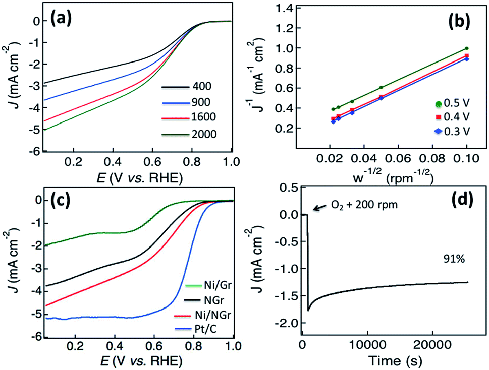 | ||
| Fig. 4 (a) Linear sweep voltammograms (LSVs) of Ni/NGr at different rotation frequencies at a scan rate of 10 mV s−1 in O2-saturated 0.1 M KOH(aq). (b) Koutecky–Levich plots of Ni/NGr at electrode potentials of 0.3, 0.4 and 0.5 V vs. RHE. (c) Comparison of LSV plots of Ni/Gr, NGr, Ni/NGr and Pt/C at 1600 rpm. (d) Stability test of Ni/NGr in chronoamperometry for 25000 s. | ||
In the Koutecky–Levich equation, J, JK, and JL are the measured current density, the kinetic-limiting current density and the diffusion-limiting current density, respectively; ω is the angular velocity of the disc, n is the overall number of electrons transferred in the oxygen reduction, F is the Faraday constant (96485 C mol−1), Co is the bulk concentration of oxygen (1.2 × 10⁻⁶ mol cm−3), Do is the diffusion coefficient of oxygen in 0.1 M KOH(aq) (1.9 × 10⁻⁵ cm2 s−1), v is the kinetic viscosity (0.01 cm2 s−1) and 0.2 is a constant that is valid when the rotation speed is expressed in rpm.
The Koutecky–Levich plots of J−1vs. ω−1/2 at potentials of +0.3, +0.4 and +0.5 V on the Ni/NGr electrode (Fig. 4b) show good linearity (R2 = 0.998). The electron transfer number was 3.7–3.9 in the potential range of 0.3 to 0.5 V, which indicated a four-electron process as the preferred pathway. A comparison of the linear sweep voltammetry curve of Ni/NGr with those of NGr, Ni/Gr and Pt/C (Fig. 4c) reveals the superior onset potential and current density of Ni/NGr compared to NGr and Ni/Gr. The Ni/Gr demonstrated poor ORR activity as neither the graphene nor pure nickel nanoparticles have good ORR properties,20 but in the case of Ni/NGr, the presence and distribution of nickel nanoparticles inside the nitrogen-doped graphene layers play crucial roles in the formation of a three-dimensional structure. The half-wave potential of Ni/NGr is found to be 0.62 V which is much lower than that of the benchmark Pt/C (0.8 V) but comparable with those of Ir/C (0.69) and RuO/C (0.68) (Table T1 in the ESI†). However the kinetic current density (4.6 mA cm−2) is comparatively closer to the kinetic current density of Pt/C (5.2 mA cm−2). Even though pure nickel is not a good catalyst for the ORR, the presence of nickel oxide with highly catalytically active sites of nitrogen-doped graphene enhanced the adsorption of oxygen in the solution and thus improved the kinetic current density.35 The electrocatalytic stability of Ni/NGr was also investigated by continuous chronoamperometric measurements at a constant potential of +0.6 V (Fig. 4d). The increment of current density was observed with the addition of oxygen to the solution as well as keeping the rotation speed at 200 rpm. A constant current density curve after stabilization was observed for a long cycle time and even at 25000 s around 91% of its initial current density was retained.
Electrocatalytic activity towards the oxygen evolution reaction (OER)
Based on the efficient electrocatalytic OER activity of nickel nanoparticles26 and nitrogen-doped graphene,11,28 the OER properties of the hybrid electrode material of Ni/NGr are investigated by sweeping the RDE potential from 1.0 to 2.0 V. From the LSV curves of Ni/NGr, Ru/C, NGr, Ni/Gr and Pt/C plotted in Fig. 5a, the onset potentials were measured to be 1.48, 1.46, 1.56, 1.49 and 1.68 V respectively. The potentials for a current density of 10 mA cm−2 for Ni/NGr, Ru/C, NGr, Ni/Gr and Pt/C were evaluated at 1.62, 1.64, 1.76, 1.78 and 1.88 V respectively as the potential required to oxidize water at the current density of 10 mA cm−2 is used to judge the OER activity. Therefore, Ni/NGr exhibited a similar onset potential and lower potential to oxidize water at the current density of 10 mA cm−2 compared to Ru/C (one of the best electrocatalysts for the OER at present) and they were superior to those of Pt/C. Even though the Ni/Gr showed low onset potential the LSV curve indicated a two-step process due to the poorer electrocatalytic properties of graphene. The Tafel slopes for Ni/NGr, Ru/C and Pt/C were about 98, 109 and 238 mV per decade respectively indicating the better OER activity of Ni/NGr (Fig. 5b). The high exchange current density and smaller Tafel slope indicated that the OER facilitated a kinetically more efficient pathway compared to RuO/C and Pt/C. The high distribution of nickel nanoparticles along with the high atomic percentage of nitrogen including a high percentage of pyridinic N and graphitic N on the edges of the surface creates active sites for efficient bi-catalysis reaction for oxygen reduction and evolution. The atomic doping of nickel with the configurations of NiO, NiOOH and β-Ni(OH)2 played a crucial role to enhance the intrinsic catalytic activity of the composite.36,37 Upon comparison of bifunctional electrocatalysis with Pt/C measured using LSV plots obtained at 1600 rpm in oxygen-saturated 0.1 M KOH (Fig. 5c), a comparable ORR with a four electron transfer pathway and better OER activity of Ni/NGr were observed. In the ORR, the onset potential and current density of Ni/NGr were lower than those of commercial Pt/C as it is the state-of-the-art ORR electrode; however in the OER the good catalytic activity of Ni/NGr was revealed by its lower onset potential and higher current density than Pt/C. | ||
| Fig. 5 (a) Linear sweep voltammograms (LSV) of Ni/NGr, Ru/C, NGr, Ni/Gr and Pt/C at a scan rate of 10 mV s−1 in 0.1 M KOH(aq). (b) The Tafel plots of Ni/NGr, Ru/C and Pt/C. (c) LSV curves of Ni/NGr and Pt/C on an RDE (1600 rpm) in O2-saturated 0.1 M KOH(aq) at a scan rate of 10 mV s−1 showing the electrocatalytic activities towards both ORR and OER. (d) Comparison of LSV curves of Ni/NGr initially and after 1000 cycles for the OER. | ||
The OER and ORR activities of Ni/NGr are also superior to those of Ru/C, as the ORR activity of Ru/C is poor compared to that of Pt/C and nitrogen-doped carbons.15 The electrocatalytic stability of Ni/NGr for the OER is also evaluated and almost similar properties are observed after 1000 cycles (Fig. 5d). Thus this active material can be a potential platform for developing bifunctional electrocatalysts for metal–air batteries and water splitting.
Electrocatalytic activity towards the hydrogen evolution reaction (HER)
After observing the efficient ORR and OER electrocatalytic properties of Ni/NGr, the electrodes were assessed in nitrogen-saturated 0.1 M KOH electrolyte using a typical three-electrode cell at room temperature to evaluate the hydrogen evolution reaction (HER) properties. NGr, Ni/Gr and Pt/C catalysts with the same mass loading on a glassy carbon electrode were examined for comparison. The linear sweep voltammetry curves of Ni/NGr, NGr, Ni/Gr and Pt/C (Fig. 6a) at a scan rate of 5 mV s−1 in 0.1 M KOH solution demonstrated electrocatalytic activity towards the HER. | ||
| Fig. 6 (a) Linear sweep voltammograms (LSVs) of Ni/NGr, NGr, Ni/Gr and Pt/C at a scan rate of 5 mV s−1 in argon-saturated 0.1 M KOH(aq). (b) LSV curves of Ni/NGr, NGr, Ni/Gr and Pt/C at a scan rate of 5 mV s−1 in argon-saturated 0.1 M H2SO4(aq). (c) The Tafel plots of Ni/NGr and Pt/C in 0.1 M KOH(aq). (d) The Tafel plots of Ni/NGr and Pt/C in 0.1 M H2SO4(aq). | ||
Commercial Pt/C shows the best HER activity and Ni/NGr shows comparable HER activity close to that of Pt/C (Fig. 6a) in alkali medium. NGr shows poor activity toward the HER. Ni/Gr showed better HER electrocatalysis activity for water splitting compared to NGr as the Ni/NiO interface exhibits efficient hydrogen evolution electrocatalysis.38 The superior activities of Ni/NGr indicate that the active sites in Ni/NiO/NGr are associated with Ni, NiO and N. The nitrogen doping influences the HER activity of the Ni/NiO nano-interface for enhanced electrocatalysis. The HER activity of the electrodes was also investigated in acidic 0.1 M H2SO4 electrolyte (Fig. 6b) and the electrodes were found to be more active in acidic media. The potential for generating a current density of −20 mA cm−2 for Ni/NGr is −0.18 V vs. RHE which is superior to that reported for Co–NG.17 The Tafel plots in alkali medium show a Tafel slope of 166 mV per decade for Ni/NGr and 92 mV per decade for Pt/C (Fig. 6c) but in the acidic medium the Tafel plot of Ni/NGr is 38 mV per decade close to Pt/C (32 mV per decade) (Fig. 6d). The small Tafel slope of Ni/NGr showed its efficiency of hydrogen evolution in acidic media by the active electrocatalytic nano-interface of metal/nitrogen-doped graphene. The nitrogen–nickel interaction with the presence of nickel oxide forms the NGr/Ni/NiO nanointerface that provides the synergistically active sites for HER catalysis both in the acidic and alkaline media. In alkaline media, the HER pathway could be through the Volmer–Heyrovsky process or Volmer–Tafel pathways.24
| H2O + e− → Hads + OH− (Volmer) and Hads + Hads → H2 (Tafel) | (2) |
| H2O + e− → Hads + OH− (Volmer) and H2O + Hads + e− → H2 + OH− (Heyrovsky) | (3) |
Both pathways involve the adsorption of an H2O molecule, electrochemical reduction of the adsorbed H2O into adsorbed OH− and a H atom, desorption of OH− to refresh the surface and formation of a H adsorbed intermediate for H2 generation. The H atom binding energy of Ni metal is close to that of Pt; however the HER catalytic activity is worse compared with Pt.26 The exact nature of the HER of nickel/nickel oxide on nitrogen-doped graphene is still unknown. Therefore, we assume that the nature would be similar to the proposed mechanism for heterostructured NiO/Ni hybrid as OH− generated by H2O splitting could preferentially attach to the nitrogen-doped graphene/NiO site at the interface due to strong electrostatic affinity to the locally positively charged Ni2+ species and more unfilled d orbitals in Ni2+ than in Ni metal, while a nearby Ni site would facilitate H adsorption and thus the Volmer process, imparting synergistic HER catalytic activity to Ni/NiO–NGr.24
Electrocatalytic activity towards the hydrogen peroxide oxidation reaction (HPOR)
The recent attention on developing hydrogen peroxide fuel cells, hydroxide exchange membrane fuel cells and fuel cells for outer space and underwater applications requires efficient noble metal free electrodes for the hydrogen peroxide oxidation reaction (HPOR).39,40 Due to the multifunctional roles of hydrogen peroxide in fuel cells as a liquid oxidant, fuel for one-compartment or membraneless fuel cells, source of oxygen in an air-free environment and for avoiding water flooding, the importance of the use of hydrogen peroxide for developing advanced fuel cells is highly crucial, and thus the development of efficient noble-metal free electrocatalysts.40–42 Nickel supported nitrogen-doped carbon nanotubes and nickel deposited carbon fiber had been demonstrated to exhibit promising electrocatalytic properties for hydrogen peroxide oxidation reaction (HPOR) activity respectively.23,43 Observing the HPOR activity of nickel deposited carbon material, the HPOR activity of the synthesized Ni/NGr is also explored. The cyclic voltammograms of Ni/NGr in argon saturated 0.1 M NaOH solution without adding any hydrogen peroxide showed a linear feature without any oxidation or reduction peak, and a broad electrooxidation peak of hydrogen peroxide at around 0.96 V associated with a small hydrogen peroxide reduction peak at 0.85 V was observed after adding 0.5 mM solution of hydrogen peroxide (Fig. 7a).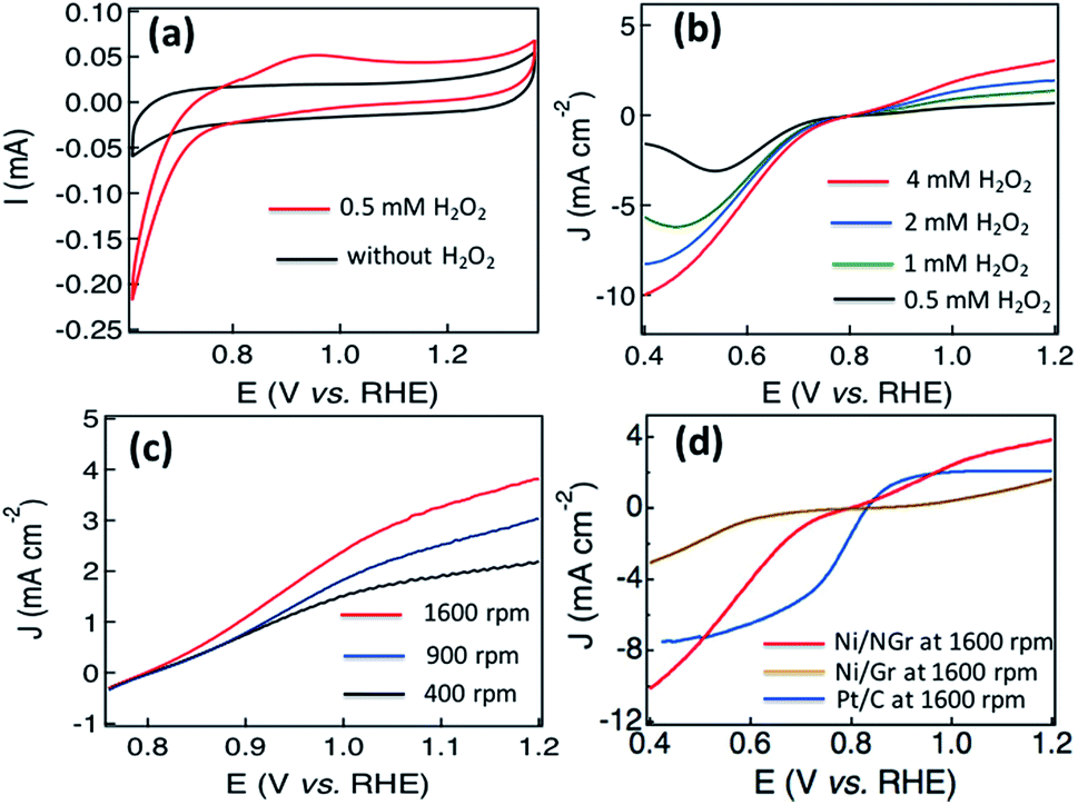 | ||
| Fig. 7 (a) Cyclic voltammograms (CV) of Ni/NGr in argon-saturated 0.1 M NaOH(aq) in the absence and presence of H2O2, (b) LSV curves of Ni/NGr at a scan rate of 5 mV s−1 in argon-saturated 0.1 M NaOH(aq) with different concentrations of H2O2, (c) the LSV curves of Ni/NGr at different rotation frequencies at a scan rate of 5 mV s−1 in argon-saturated 0.1 M NaOH(aq) with 4 mM H2O2, (d) LSV curves of Ni/NGr and Pt/C on an RDE (1600 rpm) in argon-saturated 0.1 M NaOH(aq) with 4 mM H2O2 at a scan rate of 5 mV s−1 showing electrocatalytic activities towards both HPOR and HPRR. | ||
Linear sweep voltammetry was applied to investigate the effects of current density with the raising of concentration at a rotation frequency of 1600 rpm. The increment of current density for the HPOR as well as hydrogen peroxide reduction reaction (HPRR) was observed with the increment of concentration (Fig. 7b). The adsorption of the oxygen generated in the HPOR process and the peroxide ions on the transition metal/metal oxide surface was attributed to the high current density.39 Increments of current were also observed in Fig. 7c with the increments of rotation frequency in the solution of 0.1 M NaOH with 4 mM H2O2. In alkaline media, the HPOR takes place to form oxygen, water and electrons according to the following mechanism,40
| HO−2 + OH− → O2 + H2O + 2e− | (4) |
In addition, the HPRR takes place in alkaline media according to
| O2 + 2H2O + 4e− → 4OH− | (5) |
The comparison of Ni/NGr with Ni/Gr and Pt/C for the HPOR and HPRR in Fig. 7d indicates the superior current density of Ni/NGr than Pt/C at a rotation frequency of 1600 rpm in argon saturated 0.1 M NaOH solution with 4 mM H2O2. The Ni/Gr exhibits comparatively poor HOR and HPRR activity due to the poor electrocatalytic properties of graphene. The high current density observed for the HPRR at lower potential is due to the lower activation energy of the hydrogen peroxide reduction reaction compared to the oxygen reduction reaction of oxygen molecules. The fast kinetics and large current density of the hydrogen peroxide reduction reaction might be associated with the comparatively lower energy required for breaking the single oxygen bond (146 kJ mol−1) in hydrogen peroxide than the double oxygen bond (494 kJ mol−1) in oxygen molecules.44 Thus the nanostructured Ni/NGr shows remarkable electrocatalytic activity for the HPOR associated with the HPRR in hydrogen peroxide and can be a promising electrode for the development of reversible and one compartment hydrogen peroxide based fuel cells.
Conclusions
In conclusion, we report a single pot synthesis of nickel and nickel oxide embedded N-doped graphenes (Ni/NGr) with high electrocatalytic activity. The superior electrochemical activities for the ORR, OER, HER and HPOR are attributed to the synergistic effect of the high atomic percentage of nitrogen including edge N atoms and Ni. The efficient atomic percentage of nickel doping on the carbon lattice of graphene contributes to single atom catalysis along with the embedded nickel/nickel oxide nanoparticles on the nitrogen-doped graphene surface. The quadrafunctional electrocatalytic activities of the composite for the ORR, OER, HER and HPOR demonstrate the applicability of this nanostructured electrode material for developing multifunctional energy storage and conversion devices such as reversible fuel cells, metal–air batteries, hybrid energy storage systems, platinum-free electrolyzers for complete water splitting and hydrogen peroxide based one compartment fuel cells.Conflicts of interest
There are no conflicts to declare.Acknowledgements
S. N. Faisal and E. Haque are grateful to the University of Sydney for USydIS postgraduate scholarships. N. Noorbehesht gratefully acknowledges financial support in the form of a Postgraduate Scholarship from the CSIRO-National Research Flagships Program (Future Manufacturing Flagship; No. FlagshipPhD12/03743). ATH and AIM are thankful for the ongoing support of the ARC and University of Sydney.Notes and references
- A. S. Arico, P. Bruce, B. Scrosati, J. M. Tarascon and W. V. Schalkwijk, Nat. Mater., 2005, 4, 366–377 CrossRef PubMed.
- J. Zhang, Z. Xia and L. Dai, Sci. Adv., 2015, 1, 1500564–1500583 Search PubMed.
- S. Zhai, H. E. Karahan, L. Wei, Q. Qian, A. T. Harris, A. I. Minett, S. Ramakrishna, A. K. Ng and Y. Chen, Energy Storage Materials, 2016, 3, 123–129 CrossRef.
- S. H. Joo, S. J. Choi, I. Oh, J. Kwak, Z. Liu, O. Terasaki and R. Ryoo, Nature, 2001, 412, 169–172 CrossRef PubMed.
- P. V. Kamat, J. Phys. Chem. Lett., 2012, 3, 3404 CrossRef.
- Y. Hou, Z. Wen, S. Cui, S. Ci, S. Mao and J. Chen, Adv. Funct. Mater., 2015, 25, 872–882 CrossRef.
- H. Liu, Y. Liu and D. Zhu, J. Mater. Chem., 2011, 21, 3335–3345 RSC.
- E. Pourazadi, E. Haque, S. N. Faisal and A. T. Harris, Mater. Chem. Phys., 2018, 207, 380–388 CrossRef.
- H. Wang, T. Maiyalagan and X. Wang, ACS Catal., 2012, 2, 781–794 CrossRef.
- Y. Zhao, R. Nakamura, K. Kamiya, S. Nakanishi and K. Hashimoto, Nat. Commun., 2013, 4, 2391–2398 CrossRef PubMed.
- Z. Lin, G. H. Waller, Y. Liu, M. Liu and C. P. Wong, Carbon, 2013, 53, 130–136 CrossRef.
- R. Zhou, M. Jaroniec and S. Z. Qiao, ChemCatChem, 2015, 7, 3808–3817 CrossRef.
- B. Y. Xia, Y. Yan, X. Wang and X. W. Lou, Mater. Horiz., 2014, 1, 379–399 RSC.
- J. Zhang, Z. Zhao, Z. Xia and L. Dai, Nat. Nanotechnol., 2015, 10, 444–452 CrossRef PubMed.
- R. Li, Z. Wei and X. Gou, ACS Catal., 2015, 5, 4133–4142 CrossRef.
- D. Li, M. B. Muller, S. Gilje, R. B. Kaner and G. G. Wallace, Nat. Nanotechnol., 2008, 3, 101–105 CrossRef PubMed.
- H. Fei, J. Dong, M. J. A. Jimenez, G. Y. N. D. Kim, E. L. G. Samuel, Z. Peng, Z. Zhu, F. Qin, J. Bao, M. J. Yacaman, P. M. Ajayan, D. Chen and J. M. Tour, Nat. Commun., 2015, 6, 8668–8676 CrossRef PubMed.
- S. Guo, S. Zhang, L. Wu and S. Sun, Angew. Chem., Int. Ed., 2012, 51, 11770–11773 CrossRef PubMed.
- P. Quaino, F. Juarez, E. Santos and W. Schmickler, Beilstein J. Nanotechnol., 2014, 5, 846–854 CrossRef PubMed.
- X. Liu, W. Liu, M. Ko, M. Park, M. G. Kim, P. Oh, S. Chae, S. Park, A. Casimir, G. Wu and J. Cho, Adv. Funct. Mater., 2015, 25, 5799–5808 CrossRef.
- J. Du, F. Cheng, S. Wang, T. Zhang and J. M. Chen, Sci. Rep., 2014, 4, 4386–4392 CrossRef PubMed.
- M. M. Islam, S. N. Faisal, T. Akhter, A. K. Roy, A. I. Minett, K. Konstantinov and S. X. Dou, Part. Part. Syst. Charact., 2017, 34, 1600386(1)–1600386(6) CrossRef.
- Z. Zhuang, S. A. Giles, J. Zheng, G. R. Jenness, S. Caratzoulas, D. G. Vlachos and Y. Yan, Nat. Commun., 2016, 7, 10141–10148 CrossRef PubMed.
- M. Gong, W. Zhou, M. C. Tsai, J. Zhou, M. Guan, M. Lin, B. Zhang, Y. Hu, D. Y. Wang, J. Yang, S. J. Pennycook, B. J. Hwang and H. Dai, Nat. Commun., 2014, 5, 4695–4701 CrossRef PubMed.
- J. Ren, A. Antonietti and T. P. Fellinger, Adv. Energy Mater., 2015, 5, 1401660–1401666 CrossRef.
- W. Sheng, M. Myint, J. G. Chen and J. Y. Yan, Energy Environ. Sci., 2013, 6, 1509–1512 RSC.
- S. Chen, J. Duan, J. Ran, M. Jaroniec and S. Z. Qiao, Energy Environ. Sci., 2013, 6, 3693–3699 RSC.
- S. N. Faisal, E. Haque, N. Noorbehesht, W. Zhang, A. T. Harris, T. L. Church and A. I. Minett, RSC Adv., 2017, 7, 17950–17958 RSC.
- Y. Zhu, W. Chu, N. Wang, T. Lin, W. Yang, J. Wen and X. S. Zhao, RSC Adv., 2015, 5, 77958–77964 RSC.
- A. Kamyabi-Gol, S. M. Zebarjad and S. A. Sajjadi, Colloids Surf., A, 2009, 336, 69–74 CrossRef.
- J. Wang, Z. Wei, S. Mao, H. Li and Y. Wang, Energy Environ. Sci., 2018, 11, 800–806 RSC.
- M. R. Salvadori, C. A. O. Nascimento and B. Corrêa, Sci. Rep., 2014, 4, 6404(1)–6404(6) Search PubMed.
- N. Weidler, J. Schuch, F. Knaus, P. Stenner, S. hoch, A. Maljusch, R. Schäfer, B. Kaiser and W. Jaegermann, J. Phys. Chem. C, 2017, 121, 6455–6463 CrossRef.
- P. Ganesan, A. Sivanantham and S. Shanmugam, J. Mater. Chem. A, 2016, 4, 16394–16402 RSC.
- V. Vij, S. Sultan, A. H. Harzandi, A. Meena, J. N. Tiwari, W. G. Lee, T. Yoon and K. S. Kim, ACS Catal., 2017, 7, 7196–7225 CrossRef.
- B. Kim, A. Oh, M. K. Kabiraz, Y. Hong, J. Joo, H. Baik, S. Choi and K. Lee, ACS Appl. Mater. Interfaces, 2018, 10, 10115–10122 CrossRef PubMed.
- T. Zhou, Z. Cao, P. Zhang, H. Ma, Z. Gao, H. Wang, Y. Lu, J. He and Y. Zhao, Sci. Rep., 2017, 7, 46154(1)–46154(10) Search PubMed.
- Z. Zhang, S. Liu, F. Xiao and S. Wang, ACS Sustainable Chem. Eng., 2017, 5(1), 529–536 CrossRef.
- T. Poux, A. Bnnefont, A. Ryabova, G. Kéranguéven, G. A. Tsirlina and E. R. Savinova, Phys. Chem. Chem. Phys., 2014, 16, 13595–13600 RSC.
- L. An, T. Zhao, X. Yan, Z. Zhou and P. Tan, Sci. Bull., 2015, 60, 55–64 CrossRef.
- Y. Yamada, M. Yoneda and S. Fukuzumi, Energy Environ. Sci., 2015, 8, 1698–1701 RSC.
- A. E. Sanli, Int. J. Energy Res., 2013, 7, 1488–1497 CrossRef.
- A. Aytac, M. Gurbuz and A. E. Sanli, Int. J. Hydrogen Energy, 2011, 36, 10013–10021 CrossRef.
- D. Cao, L. Sun, G. Wang, Y. Lv and M. Zhang, J. Electroanal. Chem., 2008, 621, 31–37 CrossRef.
Footnote |
| † Electronic supplementary information (ESI) available. See DOI: 10.1039/c8se00068a |
| This journal is © The Royal Society of Chemistry 2018 |