
Carbon-assisted conversion reaction-based oxide nanomaterials for lithium-ion batteries
Xueying
Li
 *a,
Lizhuang
Chen
a,
Yongquan
Qu
bc and
Yuanyuan
Ma
bc
*a,
Lizhuang
Chen
a,
Yongquan
Qu
bc and
Yuanyuan
Ma
bc
aSchool of Environmental and Chemical Engineering, Jiangsu University of Science and Technology, Zhenjiang, 212003, China. E-mail: Lixueying@just.edu.cn
bCenter for Applied Chemical Research, Frontier Institute of Science and Technology, State Key Laboratory for Mechanical Behavior of Materials, Xi'an Jiaotong University, Xi'an, 710049, China
cMOE Key Laboratory for Nonequilibrium Synthesis and Modulation of Condensed Matter, Xi'an Jiaotong University, Xi'an, 710049, China
First published on 13th March 2018
Abstract
This study presents the research progress in carbon-assisted conversion reaction-based metal oxides for high-performance anodes of lithium-ion batteries (LIBs). Conversion reaction-based metal oxides as anodes for LIBs suffer from large volume variations during charging/discharging processes, which would result in poor conductivity and fading capacity. In the past decade, various conversion reaction-based metal oxides have been integrated into different carbon nanostructures including one-dimensional nanostructures (carbon nanotubes, carbon nanofibers), two-dimensional nanostructures (graphene, graphene oxides), three-dimensional nanostructures (carbon networks, carbon foam) as well as porous carbon materials. This study describes the structures and properties of these composites and further focuses on the synergistic effects of hybrid nanostructures on the specific capacitance, rate capacity and cyclability. This study also briefly discusses charge transport, ion diffusion, and the related reaction energy barriers.
 Xueying Li | Xueying Li received her Ph.D. degree from the Center for Applied Chemical Research, Frontier Institute of Science and Technology of Xi'an Jiaotong University in 2016. She has been investigating the anode materials for lithium ion batteries. Her research is focused on the synthesis and design of transition metal oxides as anode materials for lithium ion batteries. |
 Lizhuang Chen | Lizhuang Chen is a professor at the School of Environmental and Chemical Engineering, Jiangsu University of Science and Technology. Dr Chen obtained his Ph.D. (2009) from Nanjing University. His current research interest is focused on the phase change materials (PCM) in the molecular-based system and new energy materials and devices. |
 Yongquan Qu | Dr Yongquan Qu received his B.S. in Materials Science and Engineering from Nanjing University in 2001, M.S. in Chemistry from Dalian Institute of Chemical Physics in 2004, and Ph.D. in Chemistry from the University of California, Davis in 2009. He worked as postdoctoral research fellow at the University of California, Los Angeles from 2009 to 2011. He became a faulty member of Center for Applied Chemical Research, Frontier Institute of Science and Technology, Xi'an Jiaotong University, China at 2012. His research interests focus on the heterogeneous catalysis in areas of organic synthesis, clean energy production and environmental remediation. Details can be found at: http://gr.xjtu.edu.cn/web/yongquan. |
 Yuanyuan Ma | Dr Yuanyuan Ma received her Bachelor's degree in Chemical Engineering from Nanjing University in 2002 and Ph.D in Chemistry from the University of California, Davis in 2012. She is now a faculty member of Center for Applied Chemical Research, Frontier Institute of Science and Technology, Xi'an Jiaotong University, China. Her research interests focus on heterogeneous catalysis and electrochemical catalysis of transition metals. |
1. Introduction
Economic development has impacted human life at the cost of our environment. With severe environmental pollution resulting from vast fossil-fuel consumption, there is significant interest in clean energy as a substitute for fossil fuels for the sustainable development of our economy. The investigations on clean energy sources such as solar, wind, water, geothermal, and biomass, which can reduce CO2 emission and protect the environment, have received significant attention. Energy storage is a critical component in the energy conversion storage-delivery chain. Researchers have started to develop some advanced technologies for energy storage, especially electrochemical energy storage in the form of batteries and electrochemical capacitors, which are widely used in various electrochemical systems, from renewable energy systems to portable electronic devices.Lithium-ion batteries are advanced rechargeable energy storage devices that can be applied in high-tech devices such as the iPad and iPhone mainly due to their high energy density and relatively long cycle life.
LIBs can store charge by three mechanisms:1,2
(1) Intercalation–deintercalation mechanism: some two-dimensional layer structures or 3D network structures can reversibly intercalate into the lattice without destroying the nanostructures3–6 (e.g. graphite, oxides of titanium).
(2) Alloying/de-alloying mechanism: elements, such as Si7,8 and Ge,9,10 and metals, such as Sn11,12 and Bi,13,14 can form alloys with lithium metal,15 which have unique crystal structures with different physical properties from the pristine lithium, elements, and metals.
(3) Conversion (redox) mechanism: the electrochemical reactions of transitional metal oxides during the lithiation/de-lithiation process could generate nanosized transition metal particles,16–18 catalyzing the electrochemically inactive Li2O to decompose to the metal and oxygen.
The performance of lithium ion batteries is limited by the diffusion of lithium ions in solid bulk materials. LIBs can store charge by the intercalation of lithium ions not only on the surface but also in the bulk of the active materials.19 In order to pursue efficient electrical energy storage, we should develop innovative material chemistry to design electrode materials with high special capacities, stable cyclability and high rate performance, which would be determined by the composition and structures of these electrode materials. The redox (conversion) reaction between lithium and nanosized transition metal oxides, involving multi-electron transfer,20–22 is shown in eqn (1):
| MxOy + 2yLi ↔ xM0 + yLi2O, (M = transitionmetals) | (1) |
They are therefore always considered as potential candidates for lithium ion batteries, however, due to their intrinsic material properties such as low conductivity, poor mechanical properties and side reactions on the interface between the electrolyte and electrode materials, single phased nanomaterials fail to meet the demands and even hinder the application of these materials.23–25 Dalverny et al.16 described the interfacial electrochemical/chemical/physical properties of metal oxide electrodes in conversion reactions and proved the asymmetry in the chemical and electrical responses of the interfaces in charge and discharge, which was in agreement with the voltage hysteresis observed for the metal oxide conversion/reconversion. The difference in voltages between the discharge and charge profiles, large volume expansion, low initial coulombic efficiency and rate capability need to be further optimized in the redox reaction-based nanomaterials.26–28
Carbon materials that are graphitic, diamond-like, and amorphous as dictated by the carbon precursor have good conductivity and excellent mechanical properties.29,30 Their properties are various, depending on the arrangement of their carbon atoms. They are often used to combine with the metal oxides to promote the performance of metal oxide-based anode materials for lithium ion batteries. Over the past several decades, the nanostructured carbon materials,31 such as one dimensional (1D),32,33 two dimensional (2D),34,35 three dimensional (3D) materials36,37 and porous carbon, have been engineered to be components in the composite electrode materials to promote the kinetics of lithium ion insertion/de-insertion and relax the strain of the conversion reaction-based oxide nanomaterials.38–40 Furthermore, the hybrid materials with carbon could possess high surface area, high charge storage, and high electrical conductivity for fast charge transportation.
In this review, we summarize the effects of carbon materials with different dimensions on the conversion reaction-based electrode materials for lithium ion batteries, and further inspire more novel work in the future, to put forward the development of electrode materials (Scheme 1). The structural design of the materials and investigation of corresponding structure–property relationships are discussed.
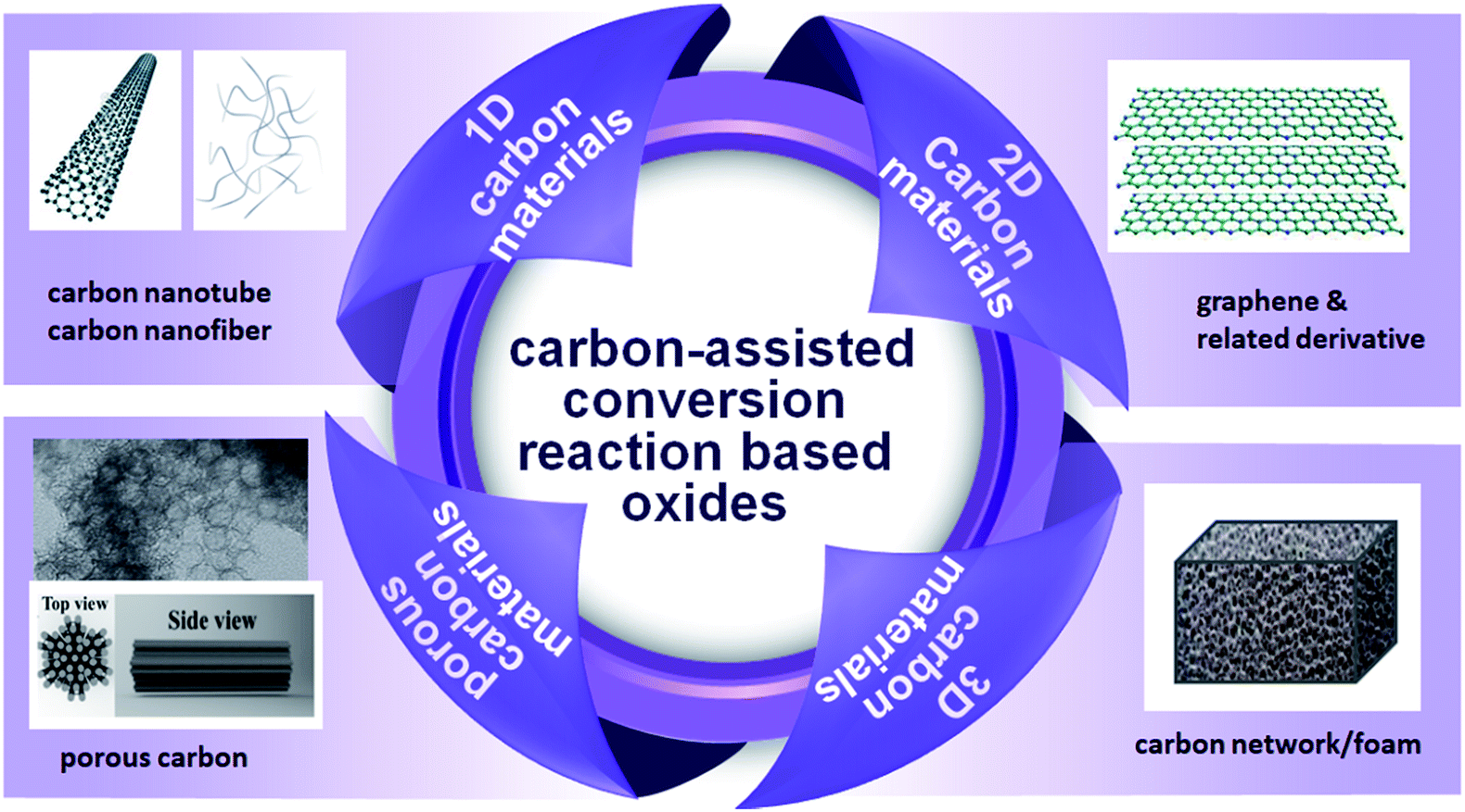 | ||
| Scheme 1 Schematic diagram of carbon-assisted conversion reaction based oxides as the anode for LIBs. The underlying materials include 1D carbon materials, 2D carbon materials, 3D carbon materials, porous carbon materials.41,42 Reproduced with permission from ref. 41. Copyright© 2011 John Wiley & Sons. Reproduced with permission from ref. 42. Copyright© 2015 Elsevier. | ||
2. One dimensional carbon based hybrid materials
2.1 Carbon nanotubes based hybrid materials
With a one-dimensional cylindrical structure, carbon nanotubes have a unique structure, high conductivity (105–106 S m−1 at 300 K), low density and high tensile strength.43–45 The graphene sheets of the carbon nanotubes can play the role of electron conduction channels. The surface functional groups on carbon nanotubes are often the faradaic redox centres (Fig. 1a and b).43,46 In the single-walled carbon nanotubes (SWCNTs), the graphene sheets are rolled up into cylinders with fullerene caps, and in multi-walled carbon nanotubes (MWCNTs) they are composed of multiple sheets.47 Lithium ions can intercalate between the MWCNT layers with lattice defects and in the interstitial sites of SWCNT bundles.45 Owing to the curvature-induced lithium condensation inside nanotubes, the capacities (300 to 600 mA h g−1) of carbon nanotubes (CNT) are significantly higher than the capacities of graphite (372 mA h g−1).48 The superior mechanical properties of carbon nanotubes could further increase the reversible capacities, e.g., SWCNTs could exhibit reversible capacities that exceed the theoretical capacities (>1116 mA h g−1).49,50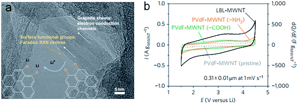 | ||
| Fig. 1 (a) Faradaic reactions between surface oxygen functional species (orange arrows) and Li, schematically illustrated on an HRTEM image of LBL–MWNT electrodes. (b) Cyclic voltammogram data for an LBL–MWNT electrode and composite electrodes of pristine MWNT, MWNT–COOH and MWNT–NH2, with the LBL–MWNT electrode having higher current and capacitance normalized to the MWNT weight, compared to the composite electrodes. Reproduced with permission.46 Copyright© 2010 Nature Publishing Group. | ||
As such, carbon nanotubes are often considered as critical components in hybrid composite materials to promote the performance of anodic materials. CNTs have high electrical conductivity (>5 × 10⁵ S m−1) and high aspect ratio (>10![[thin space (1/6-em)]](https://www.rsc.org/images/entities/char_2009.gif) 000), which allow for lower weight doping levels to achieve contiguous pathways for electron transportation.51–53 The use of CNTs as a significant support matrix in hybrid materials has several advantages:54–56 (1) to prevent the electrode materials from pulverization, the highly conductive carbon nanotube, as a glue matrix for the conversion reaction-based nanomaterials, could remain attached to the electrode's current collector. (2) The carbon nanotube could transport the electrons to and from the conversion reaction-based nanomaterials during the lithiation/delithiation processes. (3) The carbon nanotubes could be able to store additional lithium that is not reacted with the conversion reaction-based nanomaterials. Azam et al.57 investigated the adsorption capabilities and charge transfer of lithium ions attached to SWCNT and metal oxides. They found that the SWCNT/metal oxide electrode enabled an increase in specific surface area and improved the electronic conductivity and charge transfer through calculating the band structure, density of states (DOS), charge distribution and lithium adsorption energy. Recently, great advances in combining carbon nanotubes with conversion reaction-based nanomaterial composites have been made in order to promote the performance of redox reaction-based anode materials.58–60
000), which allow for lower weight doping levels to achieve contiguous pathways for electron transportation.51–53 The use of CNTs as a significant support matrix in hybrid materials has several advantages:54–56 (1) to prevent the electrode materials from pulverization, the highly conductive carbon nanotube, as a glue matrix for the conversion reaction-based nanomaterials, could remain attached to the electrode's current collector. (2) The carbon nanotube could transport the electrons to and from the conversion reaction-based nanomaterials during the lithiation/delithiation processes. (3) The carbon nanotubes could be able to store additional lithium that is not reacted with the conversion reaction-based nanomaterials. Azam et al.57 investigated the adsorption capabilities and charge transfer of lithium ions attached to SWCNT and metal oxides. They found that the SWCNT/metal oxide electrode enabled an increase in specific surface area and improved the electronic conductivity and charge transfer through calculating the band structure, density of states (DOS), charge distribution and lithium adsorption energy. Recently, great advances in combining carbon nanotubes with conversion reaction-based nanomaterial composites have been made in order to promote the performance of redox reaction-based anode materials.58–60
Metal oxide nanoparticles can be decorated on/in the carbon nanotubes33,58,61,62 and establish coaxial core–shell nanostructures.60,63,64 They efficiently give the hybrid materials two mechanisms to store lithium. The metal oxides can achieve the lithium storage based on the conversion reaction with lithium. Meanwhile, the lithium ion can also be intercalated into the CNTs. Fe3O4 as an anode material exhibits a high capacity for lithium storage (the theoretical capacity is ∼924 mA h g−1). The Fe3O4 suffers from severe volume changes during the lithiation/delithiation processes, resulting in electrode capacity loss. In order to address the problem of pulverization, hybrid nanoarchitectures have been designed. For example, He et al.65 synthesized Fe3O4 nanoparticles adhered to the surfaces of CNTs. The composite, as the anode material, exhibited the initial discharge capacity of 1035 mA h g−1 at the current density of 100 mA g−1. The capacity retention remained 645 mA h g−1 after 145 cycles, showing excellent cyclability. Subsequently, the Fe3O4/CNTs/rGO composite designed.66 As shown in Fig. 2a, Fe3O4 nanoparticles wrapped with CNTs were sandwiched by rGO layers in the composite. The discharge capacity of the Fe3O4/CNTs/rGO composite electrode was 1048 mA h g−1 after 50 cycles (Fig. 2b). The superior performance was attributed to the improved electronic conductivity and structural stability. The hollow interior of the CNTs could provide enough inner space to accommodate the volume expansion of the metal oxides. According to this design concept, Yan et al.67 synthesized Fe2O3 nanoparticles wrapped in multi-walled carbon nanotubes (Fig. 2c). Due to the relatively low loading ratio of the Fe2O3 nanoparticles, the discharge capacity could only retain 515 mA h g−1 based on the total mass after 50 cycles (Fig. 2d). However, according to the discharge capacity and mass ratio, the discharge capacity contributed by Fe2O3 nanoparticles could be calculated as 1147 mA h g−1, which was better than in the previous works.32,68–70 It is worth noting that researchers started to investigate the preparation of array-like electrode materials with superior performance. Carbon nanotube arrays facilitated ion and electron transport and acted as excellent carbon based-structures that minimized pulverization of the active materials by relaxing the stress during the charging and discharging processes.71 Reddy et al.72 fabricated hybrid coaxial nanotubes with MnO2 nanotubes in the outer shell and highly conducting CNTs in the inner core. The first discharge capacity reached to 2170 mA h g−1, but the reversible capacity was only about 500 mA h g−1 after 15 cycles with poor cyclability. Subsequently, Fan et al.69 designed a uniform Fe3O4 sheath on aligned carbon nanotube scaffolds, with the size of Fe3O4 confined to 5–7 nm, by directly drawing from CNT arrays (Fe3O4-SACNT). Under the current density of 100 mA g−1, the electrode delivered a highly reversible capacity over 800 mA h g−1 based on the total electrode mass as well as excellent rate capability (Fig. 3a). The high overall specific capacity resulted from the removal of binder and current collectors. As shown in Fig. 3b, the Fe3O4-SACNT still retained the initial morphologies after cycling. It was found that the carbon coating could further improve the stability of composite electrodes. Lou et al.73 reported coaxial carbon/MnOy/aligned carbon nanotube (ACNT) arrays over stainless-steel foil;73 MnOy particles with the size of 10–20 nm uniformly coated the CNTs (Fig. 3c). C/MnOy/ACNTs exhibited a gradual capacity increase up to about 60 cycles at the current density of 600 mA g−1. A high capacity of 737 mA h g−1 was achieved after 100 cycles (Fig. 3d). The cyclic stability was better than that of MnOy/ACNTs resulting from the external carbon layers. The layer could enhance the electrical conductivity, maintain a low mass-transfer resistance and finally stabilize the solid electrolyte interface. According to the literature,75–77 we found that the metal oxides decorated on the carbon nanotube could not keep the nanostructure stability very well during the charging/discharging processes, resulting in the poor long-term performance during lithium cycling. Therefore, people started to design nanomaterials with hierarchical structures,74,78,79 which would be capable of accommodating large volume changes and provide fast electron transport. Zhou et al.74 synthesized coaxial ZnCo2O4 shells and a nanosheet-like morphology around CNT by a simple synthetic approach (Fig. 4a). The CNT could provide high mechanical strength and excellent electrical conductivity, which facilitated efficient charge transfer. The ZnCo2O4 nanosheets on the surface of the CNT could provide numerous active sites. Thereby, the composite electrode exhibited a large reversible capacity of 1068 mA h g−1 after 100 cycles at the current density of 400 mA g−1 (Fig. 4b), whereas the pure ZnCo2O4 electrode showed a rapid decrease during the cycling. Yu et al.60 also reported the similar morphology with hierarchical NiCoO2 nanosheets supported on amorphous carbon nanotubes based on the templates and carbon source of polymeric nanotubes (PNTs) (Fig. 4c). Importantly, these PNTs could be used to prepare many other functional one-dimensional metal oxides@amorphous CNT nanostructures.80,81 NiCoO2@CNT with such unique nanostructures exhibited an ultrahigh discharge capacity of 1309 mA h g−1 at the current density of 400 mA g−1 after 300 cycles (Fig. 4d). This work illustrated that the one dimensional amorphous carbon matrix offered significant benefits for high-capacity metal oxide-based anode nanomaterials.60 Besides, Wang et al.82 designed α-Fe2O3 hollow nanohorns grown on carbon nanotube (CNT) backbones with the surface area of 96 m2 g−1. The unique hybrid structure exhibited a very stable capacity retention of 500 mA h g−1 over 100 cycles at a current density of 500 mA g−1. Although the performance was not as good as that of carbon coated CNT@Fe2O3, it was much better than that of α-Fe2O3 nanoparticles. The abovementioned works demonstrated that although the metal oxides/CNT with hierarchical structures could retain high capacity and stability at relatively low current density in short-term cycling, they still could not achieve the high rate performances in long-term cycling. Some works also focused on encapsulating nanoparticles within the hollow cavity of CNTs. However, the small bore and considerable length of the CNTs had a negative impact on the control of the uniformity of the filler material, resulting in a very low filling rate.83 Therefore, the carefully crafted combination of CNTs and conversion reaction-based oxide nanomaterials with high capacities could work synergistically to deliver high capacity and good cyclability.
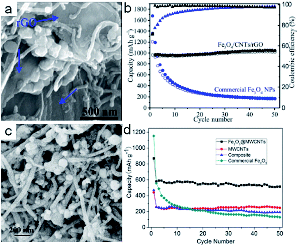 | ||
| Fig. 2 (a) SEM image of the cross-section of the Fe3O4/CNTs/rGO composite electrode. (b) Capacity retention and coulombic efficiency of the Fe3O4/CNT/rGO composite electrode at 0.2 A g−1. Reproduced with permission.66 Copyright© 2016 American Chemical Society. (c) SEM image of Fe2O3@MWCNTs. (d) Discharge capacities versus cycle number of Fe2O3@MWCNTs, the composite and commercial Fe2O3 at the current density of 100 mA g−1 between 3 and 0 V. Reproduced with permission.67 Copyright© 2013 Springer Nature. | ||
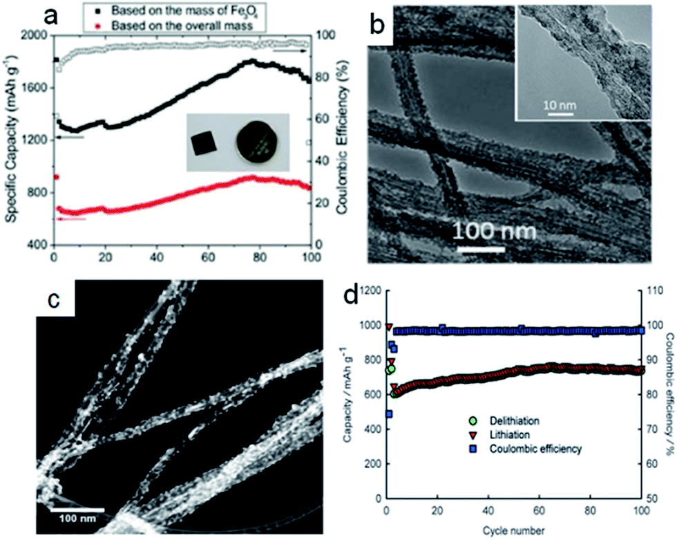 | ||
| Fig. 3 (a) Reversible specific capacity of Fe3O4-SACNT. Values based on the Fe3O4 mass and the total anode mass are in black and red, respectively. The empty black square in the curves illustrates the coulombic efficiency. Inset in (a) photograph of the Fe3O4-SACNT electrode before being sealed in a CR 2016 cell. (b) Post-cycle TEM image; inset: corresponding TEM image at high magnification. Reproduced with permission.69 Copyright© 2013 American Chemical Society. (c) The STEM image of C/MnOy/ACNTs. (d) C/MnOy/ACNTs at a current density of 60 mA g−1 for the first two cycles and 600 mA g−1 for the following cycles between 0.01 and 3.0 V versus Li/Li+; capacity was calculated based on the total weight for both carbon and manganese oxide. Reproduced with permission.73 Copyright© 2014 John Wiley & Sons. | ||
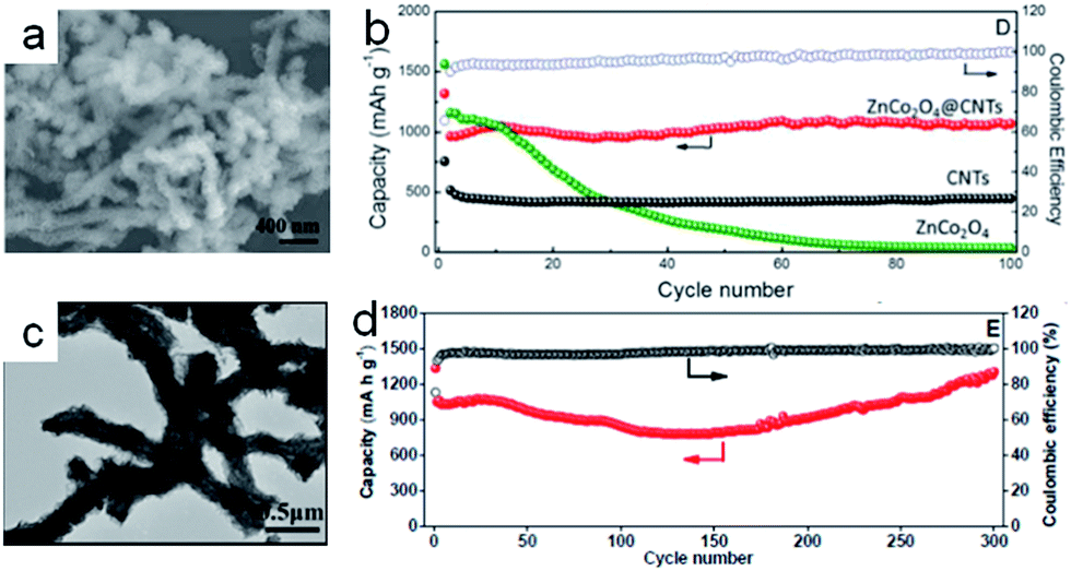 | ||
| Fig. 4 (a) SEM image of ZnCo2O4@CNT nanocomposites. (b) Comparison of the cycling performance of ZnCo2O4@CNT, CNT and pure ZnCo2O4 at a current density of 400 mA g−1.74 Copyright© 2016 Springer Nature. (c) TEM images of NiCoO2 NSs@amorphous CNT composites. (d) Cycling performance and corresponding coulombic efficiency of NiCoO2@CNT composites at a current density of 400 mA g−1. Reproduced with permission.60 Copyright© 2014 Royal Society of Chemistry. | ||
2.2 Carbon nanofibers based hybrid materials
Carbon nanofibers (CNFs) as one-dimensional materials have excellent mechanical flexibility and conductivity.84 The traditional methods to obtain the carbon nanofibers were the template method and electrospinning technique.85,86 Recently, CNFs also became attractive materials for supporting the conversion reaction-based nanomaterials in the composite electrodes to relax the strain of volume and improve the ionic and electronic transport. Meanwhile, the conversion reaction-based nanomaterials acted as the redox centers that contributed to the energy density.59,87 The strategy of combining conversion reaction-based nanomaterials (MnOx, FeOx, NiO, CuO, etc.) with the carbon nanofibers is involved in electrochemical deposition,88,89 chemical precipitation,90,91 chemical impregnation,92,93 and so on. Typically, the chemical precipitation and chemical impregnation need further heat treatment. Lin et al.88 fabricated MnOx particles on carbon nanofibers by electrochemical deposition, with the carbon nanofibers as the working electrode in the Mn(CH3COO)2 and Na2SO4 mixed solution. The discharge capacity of MnOx/CNFs was only 475 mA h g−1 with the capacity retention of 70% at 50 mA g−1. It might be that the MnOx nanoparticles were pulverized and had weak bonds to the carbon nanofibers during the charging/discharging processes. Subsequently, David Lou and his coworkers94 designed MnO/carbon nanofiber coaxial nanocables in order to reinforce the coupling effect (Fig. 5a). The CNF@MnO coaxial nanocables exhibited remarkable lithium storage properties. The reversible capacity was around 750 mA h g−1 after 150 cycles at the current density of 200 mA g−1, with the corresponding coulombic efficiency of 98% (Fig. 5b). Luo et al.95 also used a similar method to synthesize nano-Fe3O4 with an average size of 10 nm decorated on the carbon nanofiber templated by bacterial cellulose as flexible, binder-free, and cost-effective materials for lithium ion battery anodes (Fig. 5c). When the Fe3O4 content was about 34.1 wt%, the capacity of the electrode exhibited 754 mA h g−1 for 100 cycles at the current density of 100 mA g−1 (Fig. 5d). The uniform distribution of Fe3O4 nanoparticles enhanced the interconnected carbon nanofiber structure to impart the electrode with good conductivity and excellent transportation of electrons and lithium ions. Bryan D. Vogt et al.97 designed Ni/NiO/MnOx/carbon hierarchically structured fiber composites with high surface areas (150 m2 g−1). The block copolymers templated internal nanoporous morphology and the carbon in these composite fibers helped to accommodate volumetric changes during charging. The unique nanostructures could lead to lithium ion battery anodes with decent rate performances and long-term cycling stability. This study illustrated the importance of electronic conductivity and continuous charge transfer pathways necessary for high-performance lithium ion battery anodes. From the above works, we found that the nanoparticles anchored on the surface of the carbon nanofibers facilitated pulverization and needed further carbon coating to keep the structural integrity. But what happened when the nanoparticles were encapsulated in the carbon nanofibers? Cao et al.96 synthesized CoO–carbon nanofiber networks by electrospinning as binder-free anode materials for lithium ion batteries with enhanced properties. As shown in Fig. 5e, the CoO nanoparticles with diameters of about 8 nm were homogeneously distributed in the matrix of the nanofibers with diameters of 200 nm after carbonization at 650 °C (C650). The electrode C650 delivered 633 mA h g−1 after 52 cycles at a current density of 100 mA g−1 (Fig. 5f). The good performance was ascribed to nanofibers as the framework to keep the structural stability, and favorable mass and charge transport.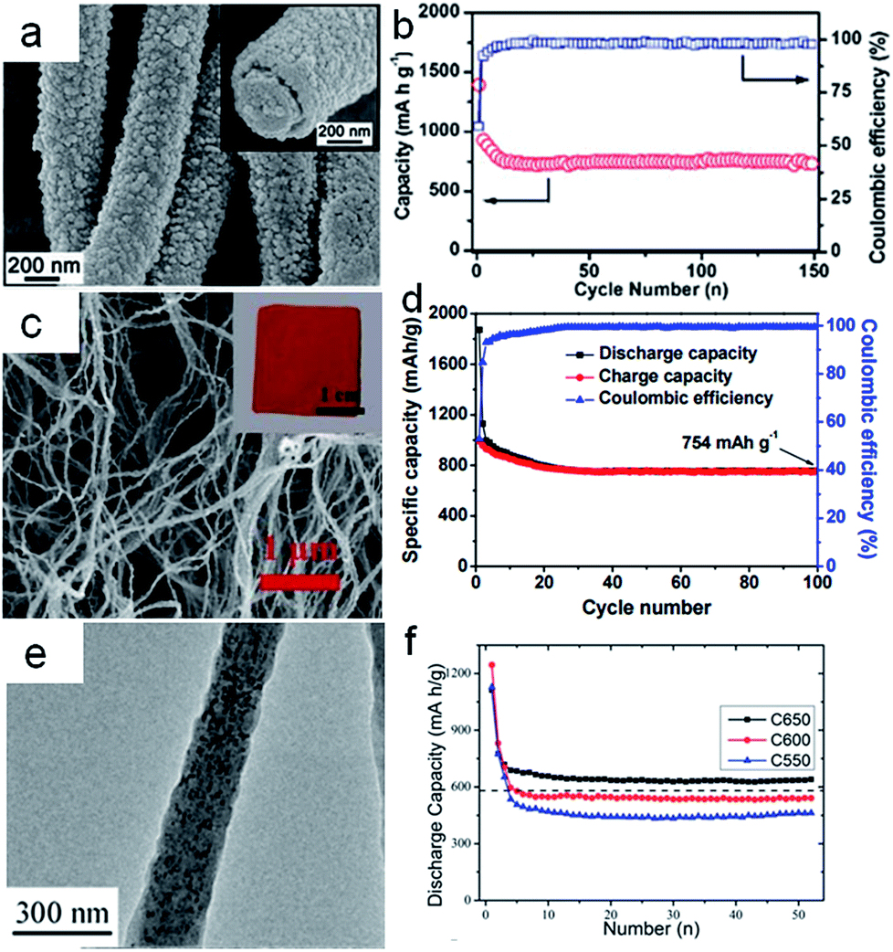 | ||
| Fig. 5 (a) TEM images of CNF@MnO nanocables. (b) Cycling performance of CNF@MnO at a current density of 200 mA g−1. Reproduced with permission.94 Copyright© 2014 Royal Society of Chemistry. (c) SEM images of Fe3O4–carbon nanofibers (CNFs) inset in (a) photograph of the Fe3O4–carbon nanofiber electrode. (d) Charge and discharge capacities with coulombic efficiency as a function of cycle number of Fe3O4 (34.1%)–carbon nanofibers (CNFs) at a current density 100 mA g−1. Reproduced with permission.95 Copyright© 2015 Royal Society of Chemistry. (e) TEM images of CoO–C obtained at 650 °C. (f) Cyclic properties of the samples C650, C600, C550 at a current density 100 mA g−1. Reproduced with permission.96 Copyright© 2013 Royal Society of Chemistry. | ||
Additionally, the theoretical specific capacity of metal oxides is much higher than that of graphite. Obviously, the capacity of the electrode is strongly dependent on the content of the metal oxides in the composites. Therefore, some scientists fabricated carbon nanofiber (CNF)/metal oxides (CNF/Co3O4,99 CNF/NiO,100 CNF/α-Fe2O3,89 CNF/CuO,101) core–shell nanowires to promote the lithium insertion performance and lithium ion diffusion. In order to enlarge the surface area of the electrode, the morphologies of the metal oxides could be controlled as mesoporous,101 flower-like,102 plate-like103 and so on. The carbon nanofiber-based electrode could exhibit high capacity and excellent rate performance, but the cyclability was very poor. Few composites could retain high capacity for long-term cycling. Jiang et al.98 designed C/MnO2 nanowires/carbon fibers as sustainable anodes for lithium ion batteries. They had a smart strategy to fabricate carbon fibers based anodes with the natural cellulose fibers in the bamboo chopsticks as the precursor. The whole fiber extraction process occurred in the alkali solution by the hydrothermal method. The graphitic carbon fibers were obtained after carbonization at 800 °C under the protection of Ar flow for 2 h (Fig. 6a). The specific surface area for the evolved carbon fibers was ∼808.25 m2 g−1. The carbon fibers contained ∼47% microporosity below 2 nm, with small mesopores centered in the range of 2–10 nm (Fig. 6b and c). The graphitic carbon fibers showed far better electrochemical behavior than the unseparated bulky bamboo carbons in specific energy and high rate capabilities. The electrode performance of the carbon fibers could be optimized by growing MnO2 robustly on the carbon fiber surface (Fig. 6d). The surface defects and hydrophilic functional groups of the carbon fiber were helpful for the nucleation of MnO2 on the carbon surface. The mass ratio of MnO2 in C/MnO2 nanowire/carbon fibers was about 45.7%. The C/MnO2 nanowires/carbon fibers, as anode materials for LIBs, delivered ∼710 mA h g−1 without decaying, lasting for 300 cycles (Fig. 6e). This was ascribed to the robust backbone of the carbon fibers and the conducting cable of the MnO2 nanowires. The carbon nanofibers as flexible materials could provide large specific surface areas, good electrical conductivity and adequate void space for conversion reaction-based metal oxides as anodes for lithium ion batteries. The content and morphology of the metal oxides in the hybrid materials, the relative position between metal oxides and carbon nanofibers on the nanoscale, and the pore structure of carbon nanofibers all affect the electrochemical performance of these hybrid materials in the lithium ion batteries.
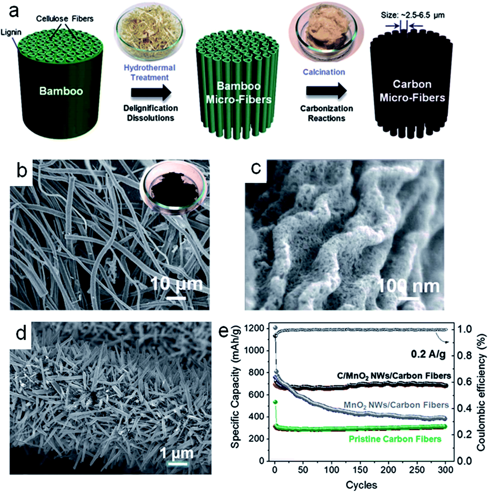 | ||
| Fig. 6 (a) Schematic diagram displaying the overall evolution of bamboo chopsticks into uniform carbon fibers. (b) Low magnification SEM image of carbon fibers. (c) High magnification SEM image of carbon fibers. (d) SEM images of the C/MnO2 NWs/carbon fibers hybrid. (e) Cycling performance of C/MnO2 NWs/carbon fibers, MnO2 NWs/carbon fibers and the pristine carbon fibers performed at 0.2 A g−1 for 300 cycles, respectively. Reproduced with permission.98 Copyright© 2014 Royal Society of Chemistry. | ||
3. Two-dimensional carbon based hybrid materials
Graphene, the most popular two dimensional carbon material, consists of large monolayer sheets of sp2 carbon atoms.35,105 As such, graphene could minimize the lateral dimensions to improve lithium ion diffusion with high reversibility. Graphene has high surface area (2630 m2 g−1),106 high intrinsic carrier mobility (200000 cm2 V−1 S−1),107 light weight and excellent mechanical properties. Singh et al. using DFT calculations revealed that the structural transformation from MWCNT to graphene nanosheets was favoured by lithium intercalation on the metal oxides/MWCNT;108 therefore, graphene is often considered as a superior material to promote the electrochemical properties of conversion reaction-based electrode materials.104,109,110
Various graphene hybrid materials have been investigated as electrodes over several years. Graphene is often combined with metal,12,111–113 metal oxide114–117 or silicon7,8 to promote the electrochemical performance of the electrode. Cheng et al.104 reported six models describing graphene/metal oxide composites. As illustrated in Fig. 7, the six structural models are as follows: (a) the anchored model with nano-sized particles anchored on graphene surfaces (Fig. 7a); (b) the wrapped model with particles wrapped by graphene (Fig. 7b); (c) the encapsulated model with particles encapsulated in graphene (Fig. 7c); (d) the sandwich-like model, where the nanoparticles are squeezed between two graphene layers creating a sandwich-like structure (Fig. 7d); (e) the layered model, alternating layers of nanoparticles and graphene (Fig. 7e); (f) the mixed model, where graphene and nanoparticles are mechanically mixed with graphene, forming a conductive network among the nanoparticles (Fig. 7f). Chemically derived graphene sheets contain carboxylic, hydroxyl, epoxide and other functional groups118–120 on the surface that can interact with metal oxides, and the functional groups on the graphene sheets could increase the defects on the graphene. Several calculation investigations demonstrated that graphene with defects was more suitable for lithium storage with high capacity than pristine graphene with graphitic structure.121,122 The presence of defects could enhance the adsorption energy of lithium in the region near the defect.123,124 The Li/C ratio in the intercalation compound could therefore be significantly increased in the graphene-based materials. Fan et al.125 proved that lithium ions can diffuse freely in the direction perpendicular to the graphene sheets that have double-vacancy and high-order defects. Hou et al.126 described the effects of topological defects on the lithium adsorption on the graphene. They found that the energy barrier for the diffusion of lithium atoms on the graphene along the boundary was lower than that perpendicular to boundary. Therefore, lithium atoms tended to migrate from non-boundary sites toward the boundary zone and charge could be transferred from lithium atoms to their nearest neighbouring carbon atoms.127 Strongly coupled inorganic–graphene hybrid electrode materials can afford higher specific capacity and rate capability. Significant synergistic effects often occur in graphene/metal oxide composites because of size effects and interfacial interactions.129,130 Metal oxides can suppress the re-stacking of graphene during the charging/discharging processes.131–133 The functions of graphene in the anode materials for lithium ion batteries are summarized as follows: (a) the graphene as a 2D support can uniformly anchor or disperse metal oxides with well-defined sizes, morphologies and crystallinity. (b) The graphene as a 2D conductive template can improve the poor electrical properties and charge transfer pathways of metal oxides. (c) Graphene can suppress the volume change and agglomeration of metal oxides. (d) The functional groups on graphene ensure good interfacial interactions and electrical contacts between graphene and metal oxides. Due to these synergistic effects, the integration of graphene and metal oxides in composites fully uses each active component and consequently achieves excellent electrochemical performance in lithium ion batteries. In particular, the strong anchoring effect between small nanoparticles and graphene afford short diffusion lengths of ions and enhance electron transport, leading to improved stability of the electrode during cycling. However, most metal oxides/graphene composites with the decorated model have fading capacity during cycling.134–139 The morphologies of metal oxides decorating the surface of graphene have been tailored in some cases in order to increase the interfacial interaction between the metal oxides and graphene to promote the charge transfer in the electrode materials. Pinna et al.140 developed a general microwave-assisted non-aqueous sol–gel approach at a variety of temperatures and composition ranges to control the final particle size, density and distribution of iron oxides selectively grown in situ at the surface of graphene oxide (GO). Combined with the TEM images and the data from X-ray absorption near edge spectroscopy (XANES) of the composites, they found that with higher GO content, the particle density on the reduced graphene oxide decreased. The concentration of surface defects (e.g., oxygenated species) in the graphene, as a higher defect concentration, would lead to a higher nucleation density and therefore to smaller particles in the final material. The effect resulted in the iron oxide/reduced graphene oxide composites having 1050 mA h g−1 at the current density of 100 mA g−1, and 500 mA h g−1 at the high current density of 1600 mA g−1. In particular, Ning et al.128 fabricated ∼3 nm Fe2O3 nanoparticles uniformly distributed in the nanopores of nanomesh graphene (NMG) by the adsorption–precipitation process. The size of Fe2O3 would be increased with the increased amount of FeCl3, as shown in Fig. 8a–c. The increased size of Fe2O3, impeded the formation of a uniform composite. Thereby, the 10% Fe–NMG composite exhibited superior capacity and gradually increased from 814 to 883 mA h g−1 after 100 cycles, much higher than the other materials (Fig. 8d). The excellent cycling performance of the 10% Fe–NMG composite was attributed to the good dispersion of nanoparticles on the NMG, which efficiently prevented the aggregation and kept the structural stability. Similarly, the metal oxides with nanorods,34,141 nanocubes142,143 and nanowires144,145 were also decorated on the reduced graphene oxides. Zhou et al.146 confirmed the oxygen bridges between metal oxide nanosheets and graphene by first-principles calculations. The calculated adsorption energies (1.37 eV for graphene with hydroxyl) were much lower than the calculated diffusion barriers (2.23 eV for graphene with hydroxyl) of the Ni atoms on the oxygenated graphene surface. The strong C–O–Ni bridge facilitated fast electron hopping from graphene to NiO and thus the reversible lithiation and delithiation of NiO. Therefore, the nanostructures could allow highly reversible capacities and excellent rate performances in short-term cycling. Subsequently, Guo et al.147 combined layered α-Fe2O3 nanodisks and reduced graphene oxide via oxygen bridges. They found that such oxygen bridges between metal oxides and graphene were beneficial to lithium ion storage. The Fe atoms anchored on the reduced graphene oxide might facilitate fast electron hopping from graphene to α-Fe2O3 nanodisks during the lithiation/delithiation processes. The excellent electrical conductivity of graphene, the large contact area between α-Fe2O3 nanodisks and reduced graphene oxides and the layered nanostructure could enhance the reaction kinetics of the composites; the layered α-Fe2O3/rGO composite delivered the capacity of 931 mA h g−1 at 0.2 A g−1 after 50 cycles. Even at a high current density of 10 A g−1, the composites showed much higher capacity (337 mA h g−1). However, the exposed metal oxide nanoparticles on the graphene surface were prone to aggregate, resulting in volume expansion and a decreased electrochemical performance.
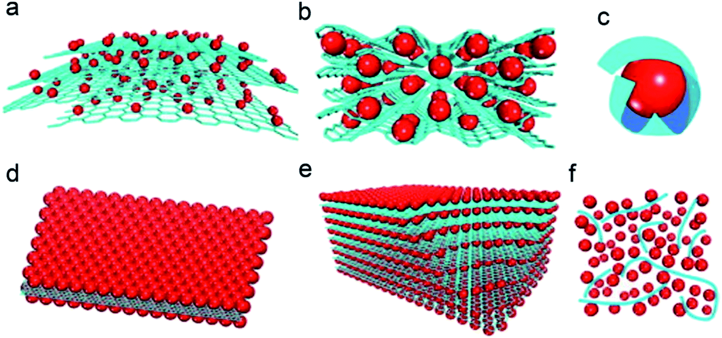 | ||
| Fig. 7 Schematic diagram of the structural models of graphene-based hybrid materials. (a) Anchored model: nanosized oxide particles are anchored on the surface of graphene. (b) Wrapped model: metal oxide particles are wrapped by graphene. (c) Encapsulated model: oxide particles are encapsulated by graphene. (d) Sandwich-like model: graphene serves as a template for the creation of a metal oxide/graphene/metal oxide sandwich-like structure. (e) Layered model: a structure composed of alternating layers of metal oxide nanoparticles and graphene. (f) Mixed model: graphene and metal oxide particles are mechanically mixed and graphene forms a conductive network among the metal oxide particles. Red: metal oxide particles; blue: graphene sheets. Reproduced with permission.104 Copyright© 2012 Elsevier. | ||
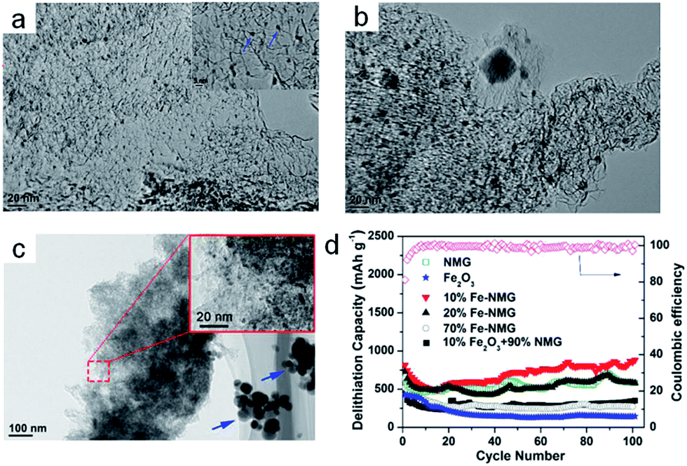 | ||
| Fig. 8 (a) TEM image of 10% Fe–NMG. The inset picture shows the high-magnification TEM image of the 10% Fe–NMG composite. (b) TEM image of 20% Fe–NMG. (c) TEM image of 70% Fe–NMG. The inset picture shows the high-magnification TEM image of the 70% Fe–NMG composite. (d) Cycling stability at the current density of 1000 mA g−1 for as-prepared materials. Reproduced with permission.128 Copyright© 2014 American Chemical Society. | ||
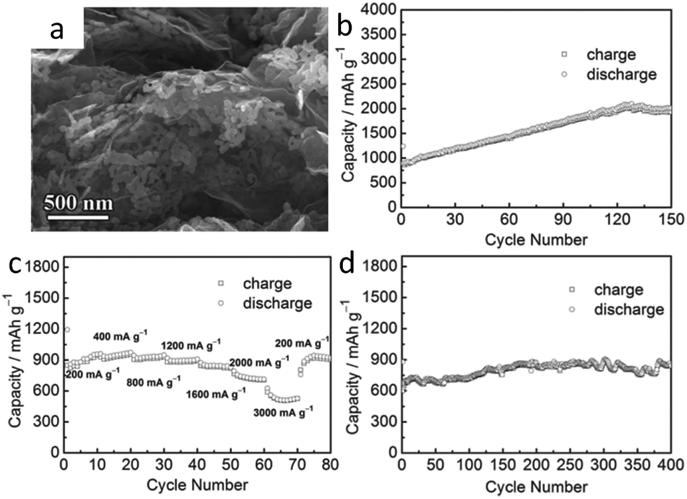
The performance of lithium ion batteries in the wrapped model of graphene-based metal oxides was better than that in the anchored model. Representative research in this area, which achieved high capacity and stable cyclability properties, includes Fe2O3 wrapped with few layered graphene, conducted by Zhu et al.,148 graphene-wrapped Fe3O4–graphene nanoribbons by Tour et al.,149 graphene nanoscroll-wrapped of Fe3O4 nanoparticles by Yan et al.150 and graphene wrapped mesoporous cobalt oxide hollow spheres by Lian et al.151 The high capacity and stable cyclability properties were achieved in these works. Especially, Huang et al.152 explored a hybrid material consisting of MnO nanocrystals grown on conductive graphene nanosheets (Fig. 9a), which exhibited 2014.1 mA h g−1 after 150 cycles at 200 mA g−1 (Fig. 9b), even though the current density got to 3000 mA g−1, the capacity was still 625.8 mA h g−1 (Fig. 9c). After 400 cycles, the electrode delivered 843.3 mA h g−1 at 2000 mA g−1 with only 0.01% capacity loss per cycle (Fig. 9d). Such highly reversible capacity, excellent rate capability and superior cyclability were attributed to the long-term stable reconstruction nanoarchitecture of graphene-supported ultrafine MnO nanoparticles with a short transportation length for both lithium ions and electrons. More work should be conducted on designing conversion electrodes that can form a stable electrochemical system during cycling in order to achieve superior lithium storage properties. In these hybrid materials, the contact efficiency of graphene with metal oxides is an important factor in influencing the electrochemical performance. Maximum contact efficiency could be achieved via a face-to-face contact between the graphene sheets and metal oxides nanoparticles; thereby, higher capacity and better rate properties can be achieved in other models of graphene-based hybrid materials focusing on sandwich-like structures and layer structures. Sandwich-like graphene-based metal oxides could not only tackle the aggregation of nanoparticles, but could also maintain the high conductivity of the electrode. Wang et al.153 fabricated Fe2O3–graphene sheet-on-sheet sandwich-like nanocomposites. The composites had a high reversible capacity of 662.4 mA h g−1 at 1000 mA g−1 after 100 cycles. Such improved cycling performance was attributed to the unique structural affinity between the Fe2O3 nanosheets and graphene nanosheets; similar work has been subsequently published. The sandwich graphene-based Co3O4 or NiO,154 sandwich-structured graphene–Fe3O4@carbon nanocomposites,155 sandwich-structured graphene–NiFe2O4–carbon nanocomposite,156 RGO–MnO–RGO sandwich nanostructures,157 and sandwich-like structured α-Fe2O3/graphene hybrids158 have demonstrated high reversible capacity, good cycle performance and good rate capability, compared to normal graphene-based metal oxides. This was attributed to the unique sandwich-like structure being able to separate the graphene-based metal oxides and increase the number of lithium ion intercalated metal oxides. More recently, there has been much interest in binder-free anodes with superior performance for advanced micro-scale energy devices. Dou et al.159 prepared the atomically thin mesoporous Co3O4 nanosheets/graphene composite (ATMCNs-GE) for high performance lithium ion batteries. The atomically thin mesoporous Co3O4 nanosheets and the nearly transparent graphene nanosheets of 1.2 nm in thickness are displayed clearly in Fig. 10a and b. This atomic layer-by-layer composite delivered high discharge capacities of 2014.7 mA h g−1 and 1134.4 mA h g−1 at 0.11C and 2.25C (1C equal to 890 mA g−1), respectively, and maintained a capacity retention of 92.1% even after 2000 cycles at 2.25C (Fig. 10c). Such outstanding electrochemical performance is mainly attributed to the metal oxide layer acting as a lithium ion accepting phase and the graphene layer as an electron accepting phase for the lithium storage. Meanwhile, the high specific surface area, high electrical conductivity and flexibility of graphene could enhance the electronic/ionic transportation and structural stability of the electrode. Similar results were also confirmed by Yu et al.160 and Wang et al.161
 | ||
| Fig. 9 (a) FESEM images of the as-synthesized MnO/graphene hybrid; (b) cycling performance of the prepared MnO/graphene hybrid electrode cycled at 200 mA g−1; (c) at various current densities of 200, 400, 800, 1200, 1600, 2000, and 3000 mA g−1; (d) cycling performance of the MnO/graphene electrodes at 2000 mA g−1. All carried out in the voltage range 3–0.01 V (vs. Li/Li+). Reproduced with permission.152 Copyright© 2013 John Wiley & Sons. | ||
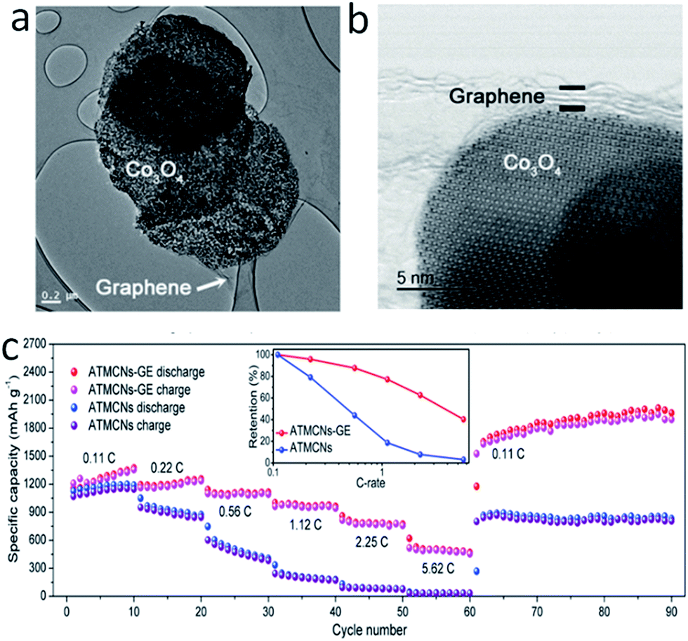 | ||
| Fig. 10 (a) Low-magnification STEM images of atomically thin mesoporous Co3O4 nanosheets/graphene composite (ATMCNs-GE). (b) High-resolution STEM images of ATMCNs-GE. (c) Rate capabilities and capacity ratios (inset) of ATMCNs-GE and ATMCNs. Reproduced with permission.159 Copyright© 2016 John Wiley & Sons. | ||
Graphene and its derivatives (RGO and functionalized GO) can be introduced into the conversion reaction-based metal oxides in several ways to improve the performance of electrode materials. The relationship between the thickness of graphene, defects, disordered features and the lithium storage mechanism in this hybrid material need to be further investigated. The large surface area, favourable wettability towards the electrolyte, high electrical conductivity and fast charge transport of metal oxides/graphene hybrid materials are expected to lead to the high performance of the robust electrode materials for LIBs.
4. Three-dimensional carbon-based hybrid materials
Very recently, considerable interest has been focused on building anode materials with large capacity, high power density and excellent cyclic stability; a specially designed heterogeneous structure is required. Three dimensional (3D) carbon networks have been proven to be beneficial for LIBs applications,163–165 and 3D carbon networks can be directly employed as the current collector, without binders and conducting agents. The interlaced networks of interconnecting pores and carbon frameworks provide perfect channels for electrolyte penetration and electron conduction, respectively. Thereby, the network can prevent not only the aggregation of metal oxide particles but also the poor connection between the active material and the current collector due to the volume change during long-term cycling. We could prepare the carbon network by chemical vapor deposition (CVD) or casting methods using a 3D porous flexible template, but the synthesis of 3D carbon networks in a facile way still faces serious challenges.There are several works that refer to the incorporation of electrochemically active nanoparticles into carbon networks using different methods. Luo et al.166 controllably synthesized mesoporous MnO/C networks by microwave irradiation. Xue et al.167 fabricated robust composite structures consisting of uniform Fe3O4 nanoparticles (∼5 nm) embedded in mesoporous carbon spheres with an average size of about 70 nm using a hydrothermal method and subsequent carbonization. The interconnecting carbon framework could provide continuous 3D electron transportation routes. The electrode had a highly reversible capacity of 271 mA h g−1 at 10 A g−1. Very recently, significant attention has been directed toward nanoparticles wrapped in graphene sheets, which could alleviate the pulverization induced by the volume changes of metal oxides. Feng et al.36 fabricated three-dimensional (3D) graphene foams cross-linked with Fe3O4 nanospheres (Fe3O4 NSs) encapsulated with graphene (Fe3O4@GS/GF). Fe3O4@GS/GF delivered a highly reversible capacity of 1059 mA h g−1 at the current density of 93 mA g−1 over 150 cycles. In order to achieve a high-performance flexible anode for the lithium ion battery with large power density, energy density, and long cyclic life, Xu and co-workers designed a 3DG/Fe2O3 aerogel with porous Fe2O3 nano-frameworks well encapsulated within graphene.162 Such unique geometric confinement of metal oxides within the graphene matrix could shorten the ion diffusion and electron transport pathway and enhance electrode stability against cycling processes for lithium storage (Fig. 11a). As shown in Fig. 11b, Fe2O3 nanoparticles wrapped in the graphene were highly porous nano-frameworks. Remarkably, the 3DG/Fe2O3 aerogel showed a discharge capacity of 523.5 mA h g−1 at the current density of 5 A g−1 even after 1200 cycles (Fig. 11c). Owing to the strong interlocking of graphene sheets in the 3DG/Fe2O3 aerogel, the composite electrode had decent mechanical stability (Fig. 11d), which could meet the demand for a flexible anode with high performance for LIBs. Similar results can also be found in other works, where the 3D graphene network integrated electrodes with free-standing superlight and highly conductive architectures have the best electrochemical performance: porous α-Fe2O3 nanorods supported on carbon nanotubes–graphene foam were obtained by the solvothermal synthesis method;168 mesoporous Co3O4 nanosheets 3D graphene network hybrid materials were obtained by the hydrothermal method;169 self-assembly of mesoporous CuO nanosheets–CNT 3D network composites by the self-assembly approach;101 3D ultrathin graphite/carbon nanotube/NiO composite by electrochemical deposition170 and subsequent annealing; a foam-like Fe3O4/C composite171 by a sol–gel-type method; MnO nanoparticles interspersed in a 3D porous carbon framework172 by wet chemical methods; anchoring Fe3O4 nanoparticles on 3D carbon nanofibers173 by hydrothermal methods and subsequent carbonization. Fan and co-workers37 have summarized different preparation methods and the associated electrochemical performance of the 3D graphene network integrated electrodes. They found that there are three different ways to combine 3D graphene networks with active materials: (1) the 3D laminate composite structure; (2) 3D bilayer composite structure; (3) 3D arrays composite structure.
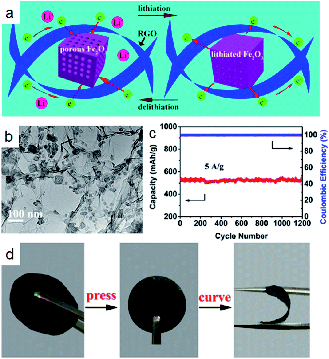 | ||
| Fig. 11 (a) The schematic of delithiation/lithiation reactions of 3DG/Fe2O3. (b) TEM image of the microstructure of 3DG/Fe2O3 prepared by annealing 3DG/PB at 250 °C for 2 h. (c) Cycling performance of 3DG/Fe2O3 at 5 A g−1. (d) Preparation of a flexible binder-free 3DG/Fe2O3 electrode. Reproduced with permission.162 Copyright© 2017 American Chemical Society. | ||
The 3D conducting host is prone to promote charge transfer and improve the kinetic properties of the composite. The good elasticity and mechanical stability of this 3D carbon structure can effectively buffer the stress/strain caused by volume variation of metal oxides during the lithium ion insertion/extraction processes. Thereby, because of the unique structural features, 3D carbon network based nano-architectures are very promising for use in high-performance LIBs. The bonding between metal oxides and the carbon surface and the synergistic effects between 3D carbon networks and conversion reaction based oxides need to be further investigated.
5. Porous carbon based hybrid materials
According to the pore dimensions, porous carbon can be classified as macroporous carbon, mesoporous carbon and microporous carbon. The macropores can minimize diffusive resistance to mass transport; the micro- and/or mesopores can provide a high surface area for active site dispersion. The combination of metal oxides with multifunctional porous carbon materials can effectively keep the metal oxide nanoparticles from aggregation, further improving the electrode stability and capacity.165The metal oxides are often embedded in the porous carbon material in order to confine the electrochemically active particles and relax the stress and strain related to the particle volume expansion/contraction during the lithium insertion/removal. Kim et al.41 synthesized Fe3O4 nanocrystals confined in mesocellular carbon foam by a “host–guest” approach. The mesoporous carbon with large pore sizes (∼20 nm) could not only accommodate a large quantity of electrochemically active materials, but also facilitates the electrolyte penetration into the pores. Even at the high current density of 2 A g−1, the capacity was still retained at 580 mA h g−1 after 150 cycles. Similar structures could be fabricated by many different methods. Ultrafine MnO nanocrystals embedded in a porous carbon matrix by carbonization of the metal–organic framework were reported by Chen et al.174 Sun et al.175 encapsulated nickel oxide or iron oxide nanocrystals into porous carbon by the sol–gel method and the annealing method. Ding and co-workers42 synthesized ultrathin NiO nanosheets anchored on a highly ordered nanostructured carbon with CMK-3 as the template (Fig. 12a and b). A highly reversible capacity (∼879 mA h g−1) could be achieved after 50 cycles at the current density of 400 mA g−1, which was higher compared to the bare CMK-3 and aggregated NiO nanosheets electrode (Fig. 12c). The superior capacity could be mainly ascribed to the unique nanosheets–mesopore structure. As shown in Fig. 12d and e, the fast lithium ion diffusion was attributed to ultrathin NiO nanosheets on the surface of the porous carbon network. The increased exposed surface of the active materials could provide more active sites for lithium storage. The ultrathin nanosheets could improve the structural stability during the lithiation/delithiation processes (Fig. 12f and g). All these works presented excellent performances of lithium storage.
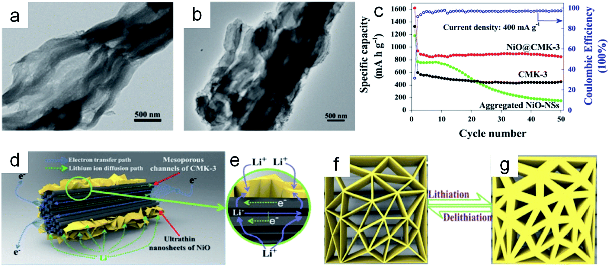 | ||
| Fig. 12 (a) TEM image of bare CMK-3 templates. (b) TEM image of NiO@CMK-3 composites. (c) Specific capacities (at a current density of 400 mA g−1) of the pure CMK-3, aggregated NiO–NSs and NiO@CMK-3 composites versus the cycle number in the voltage range 0.005–3.0 V vs. Li/Li+. The schematic representation of (d, e) the lithium ion diffusion and the electron transfer path in the nanosheets–mesoporous structure, and (f, g) the buffer function of the ultra-thin NiO–NSs during the lithiation/delithiation process. Reproduced with permission.42 Copyright© 2015 Elsevier. | ||
Recently, the N-doping porous carbon composites also attracted the interest of scientists. Nitrogen doping can improve the electrical conductivity and interfacial stability and promote the reaction kinetics of electrodes.176,177 Wu et al.178 synthesized nitrogen-doped carbon-wrapped porous single-crystalline CoO nanocubes as anodes for LIBs. A highly reversible capacity of 598.3 mA h g−1 could be retained after 50 cycles at a current density of 100 mA g−1. Similar results were also obtained by Zhang et al.179 and Wang et al.,180 showing that the composites had high electrochemical performance.
Among these porous carbonaceous materials, ordered mesoporous carbons (OMCs) have drawn much attention due to their high surface area and large pore volume, as well as the control of metal oxide nanoparticle size grown inside the well-defined mesopores, which could further prevent particle aggregation in the lithium cycling. For example, Wang et al.181 fabricated dual-template ordered mesoporous carbon/Fe2O3 nanowires as lithium ion battery anodes. The composites have high structural stability – a reversible lithium storage capacity of 819 mA h g−1 at the current density of 0.5 A g−1 after 1200 cycles. The related research in this area includes highly dispersed Fe3O4 nanocrystals on ordered mesoporous carbon by Mu et al.,182 hybrids of iron oxide/ordered mesoporous carbon,183 three-dimensional nanohybrids of Mn3O4/ordered mesoporous carbon by Yin et al.,184 and so on. Recently, Mu et al.185 synthesized mesoporous dual carbon armored MnO nanoparticles by a top-down strategy. MnO nanoparticle embedded N-doped carbon on reduced graphene oxide (rGO) showed outstanding reversible capacity, cyclability and rate capability, benefiting from the function of the dual carbon, mesoporous structure and the N-doping effect.
The porous carbon-based hybrid materials are different from the three-dimensional carbon-based hybrid materials, possessing high surface areas, high pore volume ratios, high accessibilities and prompt mass transport properties. However, the high content of carbon in these carbonaceous materials could have a negative impact on the specific capacity of hybrid materials, which is due to the low theoretical specific capacity of carbon. Therefore, the design of porous carbon-based hybrid materials needs to involve the appropriate weight ratio between the metal oxides and carbon materials in order to achieve high capacity and stable cyclability.
6. Summary and outlook
In this review, we covered fundamental electrochemical storage principles of lithium-ion batteries and briefly reviewed recent progress in applying carbon material-assisted conversion reaction-based metal oxides as anodes for lithium ion batteries. The conversion reaction-based oxides are considered as promising anode candidates due to their high theoretical capacity. However, the large volume expansions and relatively poor electrochemical conductivity in such electrodes during the lithium cycling result in rapid cycle fading. With outstanding electrical conductivity and unique mechanical stress, the carbon-based hybrid materials as anodes for lithium ion batteries are able to provide superior electrochemical performances. Studies using these hybrid materials with different dimensional carbon materials for the anodes of lithium ion batteries have been summarized in this review. Significant improvements in battery performances have been reported with the employment of these conversion reaction-based metal oxides and carbon hybrid materials.Although great progress has been made in building conversion-based metal oxides and carbon hybrid materials for application in the anodes of lithium ion batteries, many critical challenges still remain. Further research on the phenomenon of the increasing trend in the capacity of conversion-based metal oxides and carbon hybrid materials as the anode during lithium cycling is still lacking. The profound insights into the novel energy storage mechanisms that govern such electrode performances are expected to be entirely disclosed. The representative work by the Bruce group involves the demonstration of the pseudocapacitive mechanism in mesoporous and nanocrystal films during the lithium insertion process.186,187 Subsequently, they found that the oxygen vacancies could enhance the pseudocapacitive charge storage properties of conversion reaction based oxides. In addition, the balance between volumetric and gravimetric quantities is receiving increasing attention with respect to energy applications. The low mass density of carbon materials is favorable for gravimetric energy density and power density but yields poor volumetric values. Therefore, an appropriate mass density is required, without sacrificing the ion diffusion rate. In optimizing the electrochemical performance of carbon and conversion reaction-based hybrid materials, we need to consider the thickness and loading of the carbon-based hybrid materials. In order to satisfy practical consideration and fully reflect the detailed situations in commercial systems, the development of lithium ion full cells, including high capacity cathodes and anodes, needs more attention.
It should be noted that each device requires specific electrode materials with different charge-storage mechanisms. A suitable structural design is desirable for the high rate, high capacity and durable rechargeable electrode materials. The question of how to trade off the structural factors becomes a critical issue in anode designs. The preparation of hybrid materials with high electrical performance is usually tedious with low yield and high energy consumption. We should focus on exploiting the facile, repeatable, reliable and low-cost methods to fabricate the conversion reaction-based metal oxides and carbon hybrid materials in the future. The mechanical and electrochemical methods should be developed to design scaled-up, continuous and solvent recyclable growth methods. Meanwhile, the related monitoring methods and theoretical calculations for lithium insertion/extraction in the anode materials are also important to the carbon-assisted conversion reaction-based oxide electrode materials.
In conclusion, the improved electrochemical performance of oxides/carbon hybrid materials with different dimensions, through various methods, shows that the carbon materials could catalyze the conversion reaction-based oxides to be high capacity anodes for LIBs. In the future, with the industrialized processes of carbon material with different dimensions and the improvement of synthesis methods for hybrid materials, lithium ion batteries with large capacity, high rate performance, and long cycle life can be expected.
Conflicts of interest
There are no conflicts to declare.Acknowledgements
We acknowledge the financial support from the National 1000-Plan program and the National Natural Science Foundation of China (NSFC, No. 21671084). This work was also funded by the Scientific Research Fund for Advanced Talents in Jiangsu University of Science and Technology (No. 1112931605).References
- M. V. Reddy, G. V. Subba Rao and B. V. R. Chowdari, Chem. Rev., 2013, 113, 5364–5457 CrossRef CAS PubMed.
- J. S. Meng, H. C. Guo, C. J. Niu, Y. L. Zhao, L. Xu, Q. Li and L. Q. Mai, Joule, 2017, 8, 1–26 Search PubMed.
- Y. P. Wu, E. Rahm and R. Holze, J. Power Sources, 2003, 114, 228–236 CrossRef CAS.
- S. H. Liu, H. P. Jia, L. Han, J. L. Wang, P. F. Gao, D. D. Xu, J. Yang and S. A. Che, Adv. Mater., 2012, 24, 3201–3204 CrossRef CAS PubMed.
- M. Fehse, S. Cavaliere, P. E. Lippens, I. Savych, A. Iadecola, L. Monconduit, D. J. Jones, J. Rozière, F. Fischer, C. Tessier and L. Stievano, J. Phys. Chem. C, 2013, 117, 13827–13835 CAS.
- N. A. Kaskhedikar and J. Maier, Adv. Mater., 2009, 21, 2664–2680 CrossRef CAS.
- J. Y. Ji, H. X. Ji, L. L. Zhang, X. Zhao, X. Bai, X. B. Fan, F. B. Zhang and R. S. Ruoff, Adv. Mater., 2013, 25, 4673–4677 CrossRef CAS PubMed.
- L. W. Ji, H. H. Zheng, A. Ismach, Z. K. Tan, S. D. Xun, E. Lin, V. Battaglia, V. Srinivasan and Y. G. Zhang, Nano Energy, 2012, 1, 164–171 CrossRef CAS.
- X. W. Li, Z. B. Yang, Y. J. Fu, L. Qiao, D. Li, H. W. Yue and D. Y. He, ACS Nano, 2015, 9, 1858–1867 CrossRef CAS PubMed.
- Y. J. Cho, C. H. Kim, H. S. Im, Y. Myung, H. S. Kim, S. H. Back, Y. R. Lim, C. S. Jung, D. M. Jang, J. Park, S. H. Lim, E. H. Cha, K. Y. Bae, M. S. Song and W. I. Cho, Phys. Chem. Chem. Phys., 2013, 15, 11691–11695 RSC.
- Y. H. Xu, Q. Liu, Y. J. Zhu, Y. H. Liu, A. Langrock, M. R. Zachariah and C. S. Wang, Nano Lett., 2013, 13, 470–474 CrossRef CAS PubMed.
- G. X. Wang, B. Wang, X. L. Wang, J. Park, S. X. Dou, H. Ahn and K. Kim, J. Mater. Chem., 2009, 19, 8378–8384 RSC.
- F. H. Yang, F. Yu, Z. A. Zhang, K. Zhang, Y. Q. Lai and J. Li, Chem.–Eur. J., 2016, 22, 2333–2338 CrossRef CAS PubMed.
- H. Yin, Q. W. Li, M. L. Cao, W. Zhang, H. Zhao, C. Li, K. F. Huo and M. Q. Zhu, Nano Res., 2017, 10, 2156–2167 CrossRef CAS.
- M. N. Obrovac and V. L. Chevrier, Chem. Rev., 2014, 114, 11444–11502 CrossRef CAS PubMed.
- A. L. Dalverny, J. S. Filhol and M. L. Doublet, J. Mater. Chem., 2011, 21, 10134–10142 RSC.
- J. Reed and G. Ceder, Chem. Rev., 2004, 104, 4513–4534 CrossRef CAS PubMed.
- J. X. Zhu, T. Zhu, X. Z. Zhou, Y. Y. Zhang, X. W. Lou, X. D. Chen, H. Zhang, H. H. Hng and Q. Y. Yan, Nanoscale, 2011, 3, 1084–1089 RSC.
- M. D. Bhatt and C. O'Dwyer, Phys. Chem. Chem. Phys., 2015, 17, 4799–4844 RSC.
- X. P. Gao and H. X. Yang, Energy Environ. Sci., 2010, 3, 174–189 CAS.
- K. Zhang, Z. Hu, Z. L. Tao and J. Chen, Sci. China Mater., 2014, 57, 42–58 CrossRef.
- H. H. Lee, Y. Park, S. H. Kim, S. H. Yeon, S. K. Kwak, K. T. Lee and S. Y. Hong, Adv. Funct. Mater., 2015, 25, 4859–4866 CrossRef CAS.
- S. H. Yu, S. H. Lee, D. J. Lee, Y. E. Sung and T. Hyeon, Small, 2016, 12, 2146–2172 CrossRef CAS PubMed.
- X. Y. Li, Z. Y. Zhang, J. Li, Y. Y. Ma and Y. Q. Qu, J. Mater. Chem. A, 2015, 3, 18649–18656 CAS.
- H. B. Wu, J. S. Chen, H. H. Hng and X. Wen Lou, Nanoscale, 2012, 4, 2526–2542 RSC.
- V. Etacheri, R. Marom, R. Elazari, G. Salitra and D. Aurbach, Energy Environ. Sci., 2011, 4, 3243–3262 CAS.
- J. Jiang, Y. Y. Li, J. P. Liu, X. T. Huang, C. Z. Yuan and X. W. Lou, Adv. Mater., 2012, 24, 5166–5180 CrossRef CAS PubMed.
- Y. G. Wang, H. Q. Li, P. He, E. Hosono and H. S. Zhou, Nanoscale, 2010, 2, 1294–1305 RSC.
- S. L. Candelaria, Y. Y. Shao, W. Zhou, X. L. Li, J. Xiao, J. G. Zhang, Y. Wang, J. Liu, J. H. Li and G. Z. Cao, Nano Energy, 2011, 1, 195–220 CrossRef.
- D. S. Su and R. Schlögl, ChemSusChem, 2010, 3, 136–168 CrossRef CAS PubMed.
- I. Lahiri and W. B. Choi, Crit. Rev. Solid State Mater. Sci., 2013, 38, 128–166 CrossRef CAS.
- C. M. Ban, Z. C. Wu, D. T. Gillaspie, L. Chen, Y. Yan, J. L. Blackburn and A. C. Dillon, Adv. Mater., 2010, 22, 145–149 CrossRef PubMed.
- Z. Y. Cao and B. Q. Wei, J. Power Sources, 2013, 241, 330–340 CrossRef CAS.
- M. Fu, Q. Z. Jiao and Y. Zhao, J. Mater. Chem. A, 2013, 1, 5577–5586 CAS.
- X. Huang, X. Y. Qi, F. Boey and H. Zhang, Chem. Soc. Rev., 2012, 41, 666–686 RSC.
- W. Wei, S. B. Yang, H. X. Zhou, I. Lieberwirth, X. L. Feng and K. Müllen, Adv. Mater., 2013, 25, 2909–2914 CrossRef CAS PubMed.
- X. H. Xia, D. L. Chao, Y. Q. Zhang, Z. X. Shen and H. J. Fan, Nano Today, 2014, 9, 785–807 CrossRef CAS.
- Z. Li, Z. Liu, H. Y. Sun and C. Gao, Chem. Rev., 2015, 115, 7046–7117 CrossRef CAS PubMed.
- Z. B. Yang, J. Ren, Z. T. Zhang, X. L. Chen, G. Z. Guan, L. B. Qiu, Y. Zhang and H. S. Peng, Chem. Rev., 2015, 115, 5159–5223 CrossRef CAS PubMed.
- F. Yao, D. T. Pham and Y. H. Lee, ChemSusChem, 2015, 8, 2284–2311 CrossRef CAS PubMed.
- E. Kang, Y. S. Jung, A. S. Cavanagh, G.-H. Kim, S. M. George, A. C. Dillon, J. K. Kim and J. Lee, Adv. Funct. Mater., 2011, 21, 2430–2438 CrossRef CAS.
- Z. Y. Fan, J. Liang, W. Yu, S. J. Ding, S. D. Cheng, G. Yang, Y. L. Wang, Y. X. Xi, K. Xi and R. V. Kumar, Nano Energy, 2015, 16, 152–162 CrossRef CAS.
- A. C. Dillon, Chem. Rev., 2010, 110, 6856–6872 CrossRef CAS PubMed.
- H. Zhang, G. P. Cao and Y. S. Yang, Energy Environ. Sci., 2009, 2, 932–943 CAS.
- S. W. Lee, N. Yabuuchi, B. M. Gallant, S. Chen, B. S. Kim, P. T. Hammond and Y. Shao Horn, Nat. Nanotechnol., 2010, 5, 531–537 CrossRef CAS PubMed.
- N. Karousis, N. Tagmatarchis and D. Tasis, Chem. Rev., 2010, 110, 5366–5397 CrossRef CAS PubMed.
- B. J. Landi, M. J. Ganter, C. D. Cress, R. A. DiLeo and R. P. Raffaelle, Energy Environ. Sci., 2009, 2, 638–654 CAS.
- C. de las Casas and W. Z. Li, J. Power Sources, 2012, 208, 74–85 CrossRef CAS.
- K. Nishidate and M. Hasegawa, Phys. Rev. B, 2005, 71, 245418 CrossRef.
- J. J. Zhao, A. Buldum, J. Han and J. Ping Lu, Phys. Rev. Lett., 2000, 85, 1706–1709 CrossRef CAS PubMed.
- I. Lahiri, S. W. Oh, J. Y. Hwang, S. J. Cho, Y. K. Sun, R. Banerjee and W. B. Choi, ACS Nano, 2010, 4, 3440–3446 CrossRef CAS PubMed.
- K. Wang, S. Luo, Y. Wu, X. F. He, F. Zhao, J. P. Wang, K. L. Jiang and S. S. Fan, Adv. Funct. Mater., 2013, 23, 846–853 CrossRef CAS.
- J. S. Zhou, H. H. Song, B. C. Fu, B. Wu and X. H. Chen, J. Mater. Chem., 2010, 20, 2794–2800 RSC.
- D. Eder, Chem. Rev., 2010, 110, 1348–1385 CrossRef CAS PubMed.
- Y. Zhang, W. Y. Bai, X. L. Cheng, J. Ren, W. Weng, P. N. Chen, X. Fang, Z. T. Zhang and H. S. Peng, Angew. Chem., Int. Ed., 2014, 53, 14564–14568 CrossRef CAS PubMed.
- W. Wang, I. Ruiz, S. Guo, Z. Favors, H. H. Bay, M. Ozkan and C. S. Ozkan, Nano Energy, 2014, 3, 113–118 CrossRef CAS.
- L. W. Tack, M. A. Azam and R. N. A. R. Seman, J. Phys. Chem. A, 2017, 121, 2636–2642 CrossRef CAS PubMed.
- L. Y. Wang, L. H. Zhuo, H. Y. Cheng, C. Zhang and F. Y. Zhao, J. Power Sources, 2015, 283, 289–299 CrossRef CAS.
- M. J. Zhi, C. C. Xiang, J. T. Li, M. Li and N. Q. Wu, Nanoscale, 2013, 5, 72–88 RSC.
- X. Xu, B. T. Dong, S. J. Ding, C. H. Xiao and D. M. Yu, J. Mater. Chem. A, 2014, 2, 13069–13074 CAS.
- Z. L. Zhang, Y. H. Wang, M. J. Zhang, Q. Q. Tan, X. Lv, Z. Y. Zhong and F. B. Su, J. Mater. Chem. A, 2013, 1, 7444–7450 CAS.
- S. Luo, H. C. Wu, Y. Wu, K. L. Jiang, J. P. Wang and S. S. Fan, J. Power Sources, 2014, 249, 463–469 CrossRef CAS.
- X. Xu, H. Tan, K. Xi, S. J. Ding, D. M. Yu, S. D. Cheng, G. Yang, X. Y. Peng, A. Fakeeh and R. V. Kumar, Carbon, 2015, 84, 491–499 CrossRef CAS.
- H. Xia, M. Lai and L. Lu, Journal of Mater. Chem., 2010, 20, 6896–6902 RSC.
- Y. He, L. Huang, J. S. Cai, X. M. Zheng and S. G. Sun, Electrochim. Acta, 2010, 55, 1140–1144 CrossRef CAS.
- Y. Yang, J. Q. Li, D. Q. Chen and J. B. Zhao, ACS Appl. Mater. Interfaces, 2016, 8, 26730–26739 CAS.
- N. Yan, X. H. Zhou, Y. Li, F. Wang, H. Zhong, H. Wang and Q. W. Chen, Sci. Rep., 2013, 3, 3392 CrossRef PubMed.
- G. M. Zhou, D. W. Wang, P. X. Hou, W. S. Li, N. Li, C. Liu, F. Li and H. M. Cheng, J. Mater. Chem., 2012, 22, 17942–17946 RSC.
- Y. Wu, Y. Wei, J. P. Wang, K. L. Jiang and S. S. Fan, Nano Lett., 2013, 13, 818–823 CrossRef CAS PubMed.
- X. F. He, Y. Wu, F. Zhao, J. P. Wang, K. L. Jiang and S. S. Fan, J. Mater. Chem. A, 2013, 1, 11121–11125 CAS.
- R. A. Susantyoko, X. H. Wang, Q. Z. Xiao, E. Fitzgerald and Q. Zhang, Carbon, 2014, 68, 619–627 CrossRef CAS.
- A. L. M. Reddy, M. M. Shaijumon, S. R. Gowda and P. M. Ajayan, Nano Lett., 2009, 9, 1002–1006 CrossRef CAS PubMed.
- F. L. Lou, H. T. Zhou, T. D. Tran, M. E. Melandsø Buan, F. Vullum-Bruer, M. Rønning, J. C. Walmsley and D. Chen, ChemSusChem, 2014, 7, 1335–1346 CrossRef CAS PubMed.
- H. Zhou, L. Zhang, D. Y. Zhang, S. Q. Chen, P. R. Coxon, X. He, M. Coto, H. K. Kim, K. Xi and S. J. Ding, Sci. Rep., 2016, 6, 37752 CrossRef CAS PubMed.
- S. Abouali, M. Akbari Garakani, Z. L. Xu and J. K. Kim, Carbon, 2016, 102, 262–272 CrossRef CAS.
- X. L. Zhang, T. Wang, C. L. Jiang, F. Zhang, W. Y. Li and Y. B. Tang, Electrochim. Acta, 2016, 187, 465–472 CrossRef CAS.
- A. K. Mondal, H. Liu, Z. F. Li and G. X. Wang, Electrochim. Acta, 2016, 190, 346–353 CrossRef CAS.
- Y. M. Chen, L. Yu and X. W. Lou, Angew. Chem., Int. Ed., 2016, 55, 5990–5993 CrossRef CAS PubMed.
- J. Wu, W. J. Yin, W. W. Liu, P. Guo, G. B. Liu, X. C. Liu, D. S. Geng, W. M. Lau, H. Liu and L. M. Liu, J. Mater. Chem. A, 2016, 4, 10940–10947 CAS.
- M. C. Zou, Z. M. Ma, Q. F. Wang, Y. B. Yang, S. T. Wu, L. S. Yang, S. Hu, W. J. Xu, P. C. Han, R. Q. Zou and A. Y. Cao, J. Mater. Chem. A, 2016, 4, 7398–7405 CAS.
- X. Xu, S. Chen, C. H. Xiao, K. Xi, C. W. Guo, S. W. Guo, S. J. Ding, D. M. Yu and R. V. Kumar, ACS Appl. Mater. Interfaces, 2016, 8, 6004–6010 CAS.
- Z. Wang, D. Luan, S. Madhavi, Y. Hu and X. W. Lou, Energy Environ. Sci., 2012, 5, 5252–5256 CAS.
- Z. Wen, Q. Wang, Q. Zhang and J. Li, Adv. Funct. Mater., 2007, 17, 2772–2778 CrossRef CAS.
- W. H. Li, M. S. Li, K. R. Adair, X. L. Sun and Y. Yu, J. Mater. Chem. A, 2017, 5, 13882–13906 CAS.
- L. Qie, W. M. Chen, Z. H. Wang, Q. G. Shao, X. Li, L. X. Yuan, X. L. Hu, W. X. Zhang and Y. H. Huang, Adv. Mater., 2012, 24, 2047–2050 CrossRef PubMed.
- J. W. Jung, C. L. Lee, S. Yu and I. D. Kim, J. Mater. Chem. A, 2016, 4, 703–750 CAS.
- Z. Chen, J. Zhou, X. Wang, X. Liao, X. Huang and B. Shi, RSC Adv., 2016, 6, 10824–10830 RSC.
- Z. Lin, L. W. Ji, M. D. Woodroof and X. W. Zhang, J. Power Sources, 2010, 195, 5025–5031 CrossRef CAS.
- M. S. Wu, Y. H. Ou and Y. P. Lin, Electrochim. Acta, 2010, 55, 3240–3244 CrossRef CAS.
- S. Van de Vyver, J. Geboers, W. Schutyser, M. Dusselier, P. Eloy, E. Dornez, J. W. Seo, C. M. Courtin, E. M. Gaigneaux, P. A. Jacobs and B. F. Sels, ChemSusChem, 2012, 5, 1549–1558 CrossRef CAS PubMed.
- Z. X. Tai, J. W. Lang, X. B. Yan and Q. J. Xue, J. Electrochem. Soc., 2012, 159, A485–A491 CrossRef CAS.
- T. Kim, Y. Ohata, J. Kim, C. K. Rhee, J. Miyawaki and S. H. Yoon, Carbon, 2014, 80, 698–707 CrossRef CAS.
- W. Donphai, T. Kamegawa, M. Chareonpanich and H. Yamashita, Ind. Eng. Chem. Res., 2014, 53, 10105–10111 CrossRef CAS.
- G. Q. Zhang, H. B. Wu, H. E. Hoster and X. W. Lou, Energy Environ. Sci., 2014, 7, 302–305 CAS.
- Y. Z. Wan, Z. W. Yang, G. Y. Xiong and H. L. Luo, J. Mater. Chem. A, 2015, 3, 15386–15393 CAS.
- M. Zhang, E. Uchaker, S. Hu, Q. F. Zhang, T. H. Wang, G. Z. Cao and J. Y. Li, Nanoscale, 2013, 5, 12342–12349 RSC.
- S. M. Bhaway, Y.-M. Chen, Y. Guo, P. Tangvijitsakul, M. D. Soucek, M. Cakmak, Y. Zhu and B. D. Vogt, ACS Appl. Mater. Interfaces, 2016, 8, 19484–19493 CAS.
- J. Jiang, J. H. Zhu, W. Ai, Z. X. Fan, X. N. Shen, C. J. Zou, J. P. Liu, H. Zhang and T. Yu, Energy Environ. Sci., 2014, 7, 2670–2679 CAS.
- G.-H. An and H.-J. Ahn, J. Power Sources, 2014, 272, 828–836 CrossRef CAS.
- S. H. Park and W. J. Lee, RSC Adv., 2015, 5, 23548–23555 RSC.
- S. H. Park and W. J. Lee, Sci. Rep., 2015, 5, 9754 CrossRef CAS PubMed.
- S. H. Park and W. J. Lee, Carbon, 2015, 89, 197–207 CrossRef CAS.
- W. L. Yao, J. Q. Chen and H. W. Cheng, J. Solid State Electrochem., 2011, 15, 183–188 CrossRef CAS.
- Z. S. Wu, G. M. Zhou, L. C. Yin, W. C. Ren, F. Li and H. M. Cheng, Nano Energy, 2012, 1, 107–131 CrossRef CAS.
- A. Kaplan, Z. Yuan, J. D. Benck, A. Govind Rajan, X. S. Chu, Q. H. Wang and M. S. Strano, Chem. Soc. Rev., 2017, 46, 4530–4571 RSC.
- M. Pumera, Energy Environ. Sci., 2011, 4, 668–674 CAS.
- C. H. Xu, B. H. Xu, Y. Gu, Z. G. Xiong, J. Sun and X. S. Zhao, Energy Environ. Sci., 2013, 6, 1388–1414 CAS.
- I. Elizabeth, B. P. Singh, T. K. Bijoy, V. R. Reddy, G. Karthikeyan, V. N. Singh, S. R. Dhakate, P. Murugan and S. Gopukumar, Electrochim. Acta, 2017, 231, 255–263 CrossRef CAS.
- S. H. Lee, M. Kotal, J. H. Oh, P. Sennu, S. H. Park, Y. S. Lee and I. K. Oh, Carbon, 2017, 119, 355–364 CrossRef CAS.
- S. P. Wu, R. Xu, M. J. Lu, R. Y. Ge, J. Iocozzia, C. P. Han, B. B. Jiang and Z. Q. Liu, Adv. Energy Mater., 2015, 5, 1500400 CrossRef.
- S. J. Guo, S. J. Dong and E. Wang, ACS Nano, 2010, 4, 547–555 CrossRef CAS PubMed.
- J. Li, C. Y. Liu and Y. Liu, J. Mater. Chem., 2012, 22, 8426–8430 RSC.
- X. Y. Li, J. Li, X. M. Zhou, Y. Y. Ma, Z. P. Zheng, X. F. Duan and Y. Q. Qu, Carbon, 2014, 66, 713–719 CrossRef CAS.
- N. Gao and X. S. Fang, Chem. Rev., 2015, 115, 8294–8343 CrossRef CAS PubMed.
- J. S. Lee, K. H. You and C. B. Park, Adv. Mater., 2012, 24, 1084–1088 CrossRef CAS PubMed.
- X. Y. Li, Y. Y. Ma, L. Qin, Z. Y. Zhang, Z. Zhang, Y. Z. Zheng and Y. Q. Qu, J. Mater. Chem. A, 2015, 3, 2158–2165 CAS.
- X. F. Li, X. B. Meng, J. Liu, D. S. Geng, Y. Zhang, M. N. Banis, Y. L. Li, J. L. Yang, R. Y. Li, X. L. Sun, M. Cai and M. W. Verbrugge, Adv. Funct. Mater., 2012, 22, 1647–1654 CrossRef CAS.
- V. Georgakilas, J. N. Tiwari, K. C. Kemp, J. A. Perman, A. B. Bourlinos, K. S. Kim and R. Zboril, Chem. Rev., 2016, 116, 5464–5519 CrossRef CAS PubMed.
- V. Georgakilas, M. Otyepka, A. B. Bourlinos, V. Chandra, N. Kim, K. C. Kemp, P. Hobza, R. Zboril and K. S. Kim, Chem. Rev., 2012, 112, 6156–6214 CrossRef CAS PubMed.
- L. Yan, Y. B. Zheng, F. Zhao, S. J. Li, X. F. Gao, B. Q. Xu, P. S. Weiss and Y. L. Zhao, Chem. Soc. Rev., 2012, 41, 97–114 RSC.
- C. C. Ma, X. H. Shao and D. P. Cao, J. Mater. Chem., 2012, 22, 8911–8915 RSC.
- L. J. Zhou, Z. F. Hou, B. Gao and T. Frauenheim, J. Mater. Chem. A, 2016, 4, 13407–13413 CAS.
- D. Datta, J. W. Li, N. Koratker and V. B. Shenoy, Carbon, 2014, 80, 305–310 CrossRef CAS.
- Y. H. Dan, A. Kinaci, Z. J. Zhao, M. K. Y. Chan and J. Greeley, ACS Appl. Mater. Interfaces, 2014, 6, 21141–21150 Search PubMed.
- X. F. Fan, W. T. Zheng and J. L. Kuo, ACS Appl. Mater. Interfaces, 2012, 4, 2432–2438 CAS.
- L. J. Zhou, Z. F. Hou, L. M. Wu and Y. F. Zhang, J. Phys. Chem. C, 2014, 118, 28055–28062 CAS.
- Z. Q. Pang, X. H. Shi, Y. J. Wei and D. N. Fang, Carbon, 2016, 107, 557–563 CrossRef CAS.
- X. Zhu, X. Y. Song, X. L. Ma and G. Q. Ning, ACS Appl. Mater. Interfaces, 2014, 6, 7189–7197 CAS.
- K. Cheng, N. Han, Y. Su, J. Zhang and J. Zhao, Sci. Rep., 2017, 7, 41771 CrossRef CAS PubMed.
- H. L. Wang and H. J. Dai, Chem. Soc. Rev., 2013, 42, 3088–3113 RSC.
- X. B. Yu, B. Qu, Y. Zhao, C. Y. Li, Y. J. Chen, C. W. Sun, P. Gao and C. L. Zhu, Chem.–Eur. J., 2016, 22, 1638–1645 CrossRef CAS PubMed.
- M. Srivastava, J. Singh, T. Kuila, R. K. Layek, N. H. Kim and J. H. Lee, Nanoscale, 2015, 7, 4820–4868 RSC.
- M. Khan, M. N. Tahir, S. F. Adil, H. U. Khan, M. R. H. Siddiqui, A. A. Al-warthan and W. Tremel, J. Mater. Chem. A, 2015, 3, 18753–18808 CAS.
- Y. J. Chen, M. Zhuo, J. W. Deng, Z. Xu, Q. H. Li and T. H. Wang, J. Mater. Chem. A, 2014, 2, 4449–4456 CAS.
- A. K. Rai, L. T. Anh, J. Gim, V. Mathew, J. Kang, B. J. Paul, N. K. Singh, J. J. Song and J. Kim, J. Power Sources, 2013, 244, 435–441 CrossRef CAS.
- H. L. Wang, L. F. Cui, Y. Yang, H. Sanchez Casalongue, J. T. Robinson, Y. Y. Liang, Y. Cui and H. J. Dai, J. Am. Chem. Soc., 2010, 132, 13978–13980 CrossRef CAS PubMed.
- M. Zhang, D. N. Lei, X. M. Yin, L. B. Chen, Q. H. Li, Y. G. Wang and T. H. Wang, J. Mater. Chem., 2010, 20, 5538–5543 RSC.
- Z. S. Wu, W. C. Ren, L. Wen, L. B. Gao, J. P. Zhao, Z. P. Chen, G. M. Zhou, F. Li and H. M. Cheng, ACS Nano, 2010, 4, 3187–3194 CrossRef CAS PubMed.
- X. J. Zhu, Y. W. Zhu, S. Murali, M. D. Stoller and R. S. Ruoff, ACS Nano, 2011, 5, 3333–3338 CrossRef CAS PubMed.
- S. H. Yu, D. E. Conte, S. H. Baek, D. C. Lee, S. K. Park, K. J. Lee, Y. Piao, Y. E. Sung and N. Pinna, Adv. Funct. Mater., 2013, 23, 4293–4305 CrossRef CAS.
- Q. Zhou, Z. B. Zhao, Z. Y. Wang, Y. F. Dong, X. Z. Wang, Y. Gogotsi and J. S. Qiu, Nanoscale, 2014, 6, 2286–2291 RSC.
- A. Numan, N. Duraisamy, F. Saiha Omar, Y. K. Mahipal, K. Ramesh and S. Ramesh, RSC Adv., 2016, 6, 34894–34902 RSC.
- X. B. Li, S. W. Yang, J. Sun, P. He, X. P. Pu and G. Q. Ding, Synth. Met., 2014, 194, 52–58 CrossRef CAS.
- X. Cao, G. Tian, Y. Chen, J. Zhou, W. Zhou, C. Tian and H. Fu, J. Mater. Chem. A, 2014, 2, 4366–4374 CAS.
- S. Zhang, L. X. Zhu, H. H. Song, X. H. Chen and J. S. Zhou, Nano Energy, 2014, 10, 172–180 CrossRef CAS.
- G. M. Zhou, D. W. Wang, L. C. Yin, N. Li, F. Li and H. M. Cheng, ACS Nano, 2012, 6, 3214–3223 CrossRef CAS PubMed.
- J. Qu, Y. X. Yin, Y. Q. Wang, Y. Yan, Y. G. Guo and W. G. Song, ACS Appl. Mater. Interfaces, 2013, 5, 3932–3936 CAS.
- Y. K. Wang, L. C. Yang, R. Z. Hu, W. Sun, J. W. Liu, L. Z. Ouyang, B. Yuan, H. H. Wang and M. Zhu, J. Power Sources, 2015, 288, 314–319 CrossRef CAS.
- L. Li, A. Kovalchuk, H. L. Fei, Z. W. Peng, Y. L. Li, N. D. Kim, C. S. Xiang, Y. Yang, G. D. Ruan and J. M. Tour, Adv. Energy Mater., 2015, 5, 1500171 CrossRef.
- J. P. Zhao, B. J. Yang, Z. M. Zheng, J. Yang, Z. Yang, P. Zhang, W. C. Ren and X. B. Yan, ACS Appl. Mater. Interfaces, 2014, 6, 9890–9896 CAS.
- H. T. Sun, X. Sun, T. Hu, M. P. Yu, F. Y. Lu and J. Lian, J. Phys. Chem. C, 2014, 118, 2263–2272 CAS.
- Y. M. Sun, X. L. Hu, W. Luo, F. F. Xia and Y. H. Huang, Adv. Funct. Mater., 2013, 23, 2436–2444 CrossRef CAS.
- J. Kan and Y. Wang, Sci. Rep., 2013, 3, 3502 CrossRef PubMed.
- W. B. Yue, S. H. Jiang, W. J. Huang, Z. Q. Gao, J. Li, Y. Ren, X. H. Zhao and X. J. Yang, J. Mater. Chem. A, 2013, 1, 6928–6933 CAS.
- L. Zhao, M. M. Gao, W. B. Yue, Y. Jiang, Y. Wang, Y. Ren and F. Q. Hu, ACS Appl. Mater. Interfaces, 2015, 7, 9709–9715 CAS.
- E. K. Heidari, B. Zhang, M. H. Sohi, A. Ataie and J. K. Kim, J. Mater. Chem. A, 2014, 2, 8314–8322 CAS.
- T. Z. Yuan, Y. Z. Jiang, W. P. Sun, B. Xiang, Y. Li, M. Yan, B. Xu and S. X. Dou, Adv. Funct. Mater., 2016, 26, 2198–2206 CrossRef CAS.
- X. Qi, H. B. Zhang, J. T. Xu, X. Y. Wu, D. Z. Yang, J. Qu and Z. Z. Yu, ACS Appl. Mater. Interfaces, 2017, 9, 11025–11034 CAS.
- Y. H. Dou, J. T. Xu, B. Y. Ruan, Q. N. Liu, Y. D. Pan, Z. Q. Sun and S. X. Dou, Adv. Energy Mater., 2016, 6, 1501835 CrossRef.
- A. Yu, H. W. Park, A. Davies, D. C. Higgins, Z. W. Chen and X. C. Xiao, J. Phys. Chem. Lett., 2011, 2, 1855–1860 CrossRef CAS.
- R. H. Wang, C. H. Xu, J. Sun, Y. Q. Liu, L. Gao and C. C. Lin, Nanoscale, 2013, 5, 6960–6967 RSC.
- T. C. Jiang, F. X. Bu, X. X. Feng, I. Shakir, G. L. Hao and Y. X. Xu, ACS Nano, 2017, 11, 5140–5147 CrossRef CAS PubMed.
- D. Wang, R. Kou, D. Choi, Z. Yang, Z. Nie, J. Li, L. V. Saraf, D. Hu, J. Zhang, G. L. Graff, J. Liu, M. A. Pope and I. A. Aksay, ACS Nano, 2010, 4, 1587–1595 CrossRef CAS PubMed.
- X. H. Cao, Y. M. Shi, W. H. Shi, X. H. Rui, Q. Y. Yan, J. Kong and H. Zhang, Small, 2013, 9, 3433–3438 CrossRef CAS PubMed.
- S. Dutta, A. Bhaumik and K. C. W. Wu, Energy Environ. Sci., 2014, 7, 3574–3592 CAS.
- W. Luo, X. L. Hu, Y. M. Sun and Y. H. Huang, ACS Appl. Mater. Interfaces, 2013, 5, 1997–2003 CAS.
- Y. Chen, B. H. Song, M. Li, L. Lu and J. M. Xue, Adv. Funct. Mater., 2014, 24, 319–326 CrossRef CAS.
- M. Chen, J. Liu, D. Chao, J. Wang, J. Yin, J. Lin, H. Jin Fan and Z. Xiang Shen, Nano Energy, 2014, 9, 364–372 CrossRef CAS.
- H. Y. Sun, Y. G. Liu, Y. L. Yu, M. Ahmad, D. Nan and J. Zhu, Electrochim. Acta, 2014, 118, 1–9 CrossRef CAS.
- W. W. Liu, C. X. Lu, X. L. Wang, K. Liang and B. K. Tay, J. Mater. Chem. A, 2015, 3, 624–633 CAS.
- F. Wu, R. Huang, D. Mu, B. Wu and S. Chen, ACS Appl. Mater. Interfaces, 2014, 6, 19254–19264 CAS.
- S. B. Wang, Y. L. Xing, H. Z. Xu and S. C. Zhang, ACS Appl. Mater. Interfaces, 2014, 6, 12713–12718 CAS.
- Y. Z. Wan, Z. W. Yang, G. Y. Xiong, R. S. Guo, Z. Liu and H. L. Luo, J. Power Sources, 2015, 294, 414–419 CrossRef CAS.
- F. C. Zheng, G. L. Xia, Y. Yang and Q. W. Chen, Nanoscale, 2015, 7, 9637–9645 RSC.
- J. Ming, J. B. Park and Y. K. Sun, ACS Appl. Mater. Interfaces, 2013, 5, 2133–2136 CAS.
- X. Shi, H. H. Song, A. Li, X. H. Chen, J. S. Zhou and Z. K. Ma, J. Mater. Chem. A, 2017, 5, 5873–5879 CAS.
- Q. F. Wang, R. Q. Zou, W. Xia, J. Ma, B. Qiu, A. Mahmood, R. Zhao, Y. C. Yang, D. G. Xia and Q. Xu, Small, 2015, 11, 2511–2517 CrossRef CAS PubMed.
- K. W. Xie, P. Wu, Y. Y. Zhou, Y. Ye, H. Wang, Y. W. Tang, Y. M. Zhou and T. H. Lu, ACS Appl. Mater. Interfaces, 2014, 6, 10602–10607 CAS.
- L. L. Zhang, D. H. Ge, G. L. Qu, J. W. Zheng, X. Q. Cao and H. W. Gu, Nanoscale, 2017, 9, 5451–5457 RSC.
- L. Wang, Y. L. Zheng, X. H. Wang, S. H. Chen, F. G. Xu, L. Zuo, J. F. Wu, L. L. Sun, Z. Li, H. Q. Hou and Y. H. Song, ACS Appl. Mater. Interfaces, 2014, 6, 7117–7125 CAS.
- J. K. Hu, C. F. Sun, E. Gillette, Z. Gui, Y. H. Wang and S. B. Lee, Nanoscale, 2016, 8, 12958–12969 RSC.
- F. Wu, R. Huang, D. B. Mu, X. Y. Shen and B. Wu, J. Alloys Compd., 2014, 585, 783–789 CrossRef CAS.
- Z. Q. Li, X. K. Wang, C. B. Wang and L. W. Yin, RSC Adv., 2013, 3, 17097–17104 RSC.
- Z. Q. Li, N. N. Liu, X. K. Wang, C. B. Wang, Y. X. Qi and L. W. Yin, J. Mater. Chem., 2012, 22, 16640–16648 RSC.
- W. Zhang, J. N. Li, J. Zhang, J. Z. Sheng, T. He, M. Y. Tian, Y. F. Zhao, C. J. Xie, L. Q. Mai and S. C. Mu, ACS Appl. Mater. Interfaces, 2017, 9, 12680–12686 CAS.
- V. Augustyn, J. Come, M. A. Lowe, J. W. Kim, P.-L. Taberna, S. H. Tolbert, H. D. Abruña, P. Simon and B. Dunn, Nat. Mater., 2013, 12, 518–522 CrossRef CAS PubMed.
- H. S. Kim, J. B. Cook, H. Lin, J. S. Ko, S. H. Tolbert, V. Ozolins and B. Dunn, Nat. Mater., 2016, 16, 454–461 CrossRef PubMed.
| This journal is © The Royal Society of Chemistry 2018 |