
Atomic scale Pt decoration promises oxygen reduction properties of Co@Pd nanocatalysts in alkaline electrolytes for 310k redox cycles†
Yu
Zhuang
a,
Jyh-Pin
Chou
 b,
Hsin-Yi
Tiffany Chen
c,
Yang-Yang
Hsu
c,
Chih-Wei
Hu
c,
Alice
Hu
*a and
Tsan-Yao
Chen
*cd
b,
Hsin-Yi
Tiffany Chen
c,
Yang-Yang
Hsu
c,
Chih-Wei
Hu
c,
Alice
Hu
*a and
Tsan-Yao
Chen
*cd
aDepartment of Mechanical and Biomedical Engineering, City University of Hong Kong, Hong Kong. E-mail: alicehu@cityu.edu.hk
bInstitute for Solid State Physics and Optics, Wigner Research Centre for Physics, Hungarian Academy of Sciences, POB 49, Budapest, H-1525, Hungary
cDepartment of Engineering and System Science, National Tsing Hua University, Hsinchu 30013, Taiwan. E-mail: chencaeser@gmail.com
dInstitute of Nuclear Engineering and Science, National Tsing Hua University, Hsinchu 30013, Taiwan
First published on 15th December 2017
Abstract
Nanocatalysts (NCs) with Co core–Pd shell structures and surface decoration of atomic scale Pt clusters (namely Co@Pd–Pt) are synthesized by using a self-aligned wet chemical reduction method in carbon nanotube supports. The Co@Pd–Pt contains ∼2.48 at% Pt metal. It shows a 30.2-fold mass activity (2056.3 mA mg−1) of the Pt metal as compared to that of commercial Pt catalysts (67.1 mA mg−1) at 0.85 volt (vs. RHE) and shows an exceptional stability of retained current density of ∼100% vs. the initial ones in an accelerated degradation test (ADT) for over 310k cycles in an alkaline electrolyte. The results of structural characterization and electrochemical analyses reveal that the high current density with substantial stability in the ORR is attributed to a strong electronic coupling and interface lattice that extract electrons from Co and Pd atoms in the presence of atomic Pt clusters in the Pd shell. A worth noticing finding is that such exceptional electrochemical performances are developed in a novel composition window in which Pt atoms are mostly positioned in defect sites of the Pd–Co interface in the shell region.
Introduction
Redox performance of a fuel cell module is a factor of fuel decomposition kinetics/activity and over-potential losses from assembled components (gas diffusion layer, fuel channel, conducting support, and nanocatalysts (NCs) at both anode and cathode sides). In a state-of-the-art fuel cell module, cathodic NCs complete the system redox cycle via the oxygen reduction reaction (ORR) and incur the highest energy barrier (∼0.3 to 0.4 volt) as compared to that of the rest of the components including H2 dissociation in the anode (∼0.1 to 0.2 volt) and proton (hydroxide ion) diffusion in the electrolyte (∼0.05 to 0.1 volt).1 In low temperature fuel cell modules, cathodic NCs are synthesized with high noble metal (Pt in most cases) loading electrodes that incur the highest capital cost among assembled components. In addition to an unaffordable price, structural reliability and activity are indexes of commercialization of NCs in a fuel cell module.Transition metal additives are commonly adopted in Pt based binary (PtM, M denotes Co, Ni, Sn, Pd, etc.) nanocatalyst to reduce material cost. To further enhance catalytic performance, alloy or core–shell structure with Pt riched surface are designed in order to increase Pt utilization of NC in a redox reaction.2 From heterogeneous catalysis theory, the activity of NCs is positively proportional to their redox kinetics against fuel decomposition. In a heterogeneous NC, redox kinetics is dominated by three major pathways, which are (1) a bifunctional mechanism (selectivity and variety of sorption sites), (2) ligand effects (charge relocation via heteroatomic electronegativity difference), and (3) electron localization by lattice strain between the core–shell interface and intra-particle heteroatomic clusters. Among existing properties, structure and electrochemical reliability are the most important indexes for evaluating commercialization and scientific merits of NCs. The two indexes are interrelated with each other and are highly sensitive to material degradation modes of fuel cell NC layers. As shown in Scheme 1, six major pathways account for NC degradation in the redox reaction. They are (1) carbon support oxidation or decomposition to CO2via electrochemical reactions at the NC interface, (2) changes of atomic structure, crystal shape, and degree of alloying via metal corrosion in electrolyte, (3) NC growth through metal corrosion followed by re-deposition of metal ions to neighbouring NCs from residual metal ions in the electrolyte or diffusion in the carbon surfaces, (4) NC coalescence by interfacial atomic diffusion between nanoparticles, (5) poisoning or passivation by strongly bonded molecules at NC surfaces, and (6) NC detachment from the electrode as a result of severe carbon support damage in the 1st pathway or metal corrosion in the 2nd pathway.
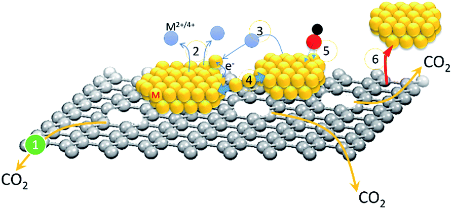 | ||
| Scheme 1 Schematic representation of degradation pathways of NCs in the oxygen reduction reaction. | ||
Pathways as mentioned above in relation to the redox activity and reliability of NCs can be optimized by manipulating their geometric configuration (i.e., interfaces between intra-particle domain, individual particle, and particle to support), chemical identity, and outfit (i.e., crystal shape, crystal size, defect density, and type/amount of decoration).2b,3 These assessments are developed based on concepts of reducing atomic diffusion coefficient in a NC and its interfaces to support as well as increase the energy barrier for metal dissolution in the electrolyte. They are dominated by the material's nature particularly when low electrochemical resistance identities (i.e., low Z transition metals of Zn, V, Co, Ni, Fe, Cu, etc.) are adopted to pursue commercialization of NCs. Among existing geometry designs in NCs, the core–shell structure with proper shell thickness and surface decoration promises low material cost, high activity, and redox stability in the ORR.1b,4 Such a unique structure possesses high interfacial lattice strain between upper and sublayer crystals. The lattice strain results in a substantial atomic distance displacement and an electron redistribution and therefore disrupts the relaxation time and reduces the adsorption energy of chemisorbed molecules in NC surfaces.
Surface modification by capping chemically inert materials (for instance, atomic scale Pt or Au clusters in the sorption site) further improves the redox stability of core–shell NCs. Those inert sub-nanometer clusters protect the defect sites and opened facets from corrosion via two pathways including geometric and electron field shielding effects. In a geometric shielding, the capping clusters form strong bonding to reinforce local structure and protect the defect sites or opened facets from interacting with protons/hydroxide in redox mediate. The strong electronegative force and lattice strain relocate electrons to nanoclusters from adjacent region (core crystal). It forms a relative strong negative field which weaken chemisorption of intermediate species in a ORR. The localized electrons build a negative field which reduces the relaxation time to weaken reaction molecules by means of improved redox stability of NCs. In the present study, ternary NCs comprising Co cores and Pd shells with atomic scale Pt clusters decorated in surface hollow sites (namely Co@Pd–Pt) are synthesized. Such a structural design optimized the heteroatomic Pt to Pd intermix shell crystal with a proper atomic scale configuration and a negative potential field for oxygen reduction. The Co@Pd–Pt improves the mass activity (MA) of Pt 30.2-fold at 0.85 volt (vs. RHE) as compared to that of commercial Pt NCs (J.M.-Pt) in an alkaline electrolyte. Most importantly, an exceptional redox stability is found in Co@Pd–Pt NCs which show no MA degradation in an accelerated degradation test (ADT) for more than 300k redox cycles (the retention current of “J.M.-Pt” is ∼50% at the 5000th cycle).
Experimental
Synthesis of atomic Pt cluster decorated Cocore–Pdshell NCs and control samples
Synthesis of atomic Pt cluster decorated Cocore–Pdshell NCs was conducted by reducing Pt4+ ions in the Pd shell surface by a wet chemical reduction method with sequential control. For improving NC attachment, a carbon nanotube support (CNT, Cnano Technology Ltd.) was acid treated in an aqueous solution of 4.0 M sulphuric acid at 80 °C for 6 h and then washed with distilled water till the pH value of the washing liquid is 6.0. After washing, the CNT powder was immersed in an ethylene glycol (EG, 99%, Sigma-Aldrich, Co.) solution of cobalt(III) chloride tri-hydrate (CoCl3·3H2O, 99%, Sigma-Aldrich Co.) and stirred at 250 rpm at 25 °C for 6 h. This solution (solution A) contained 57.1 mg CoCl3·3H2O (i.e., 15.0 mg “0.023 mmol” of Co metal ions) and 30 g EG. After immersion, 3.0 g of EG solution containing 10.0 mg (0.252 mmol) NaBH4 (99%, Sigma-Aldrich Co.) was added to solution A and stirred at 250 rpm for 15 s. Then, Pd precursor solution which comprised 1.0 g distilled water and ∼24.2 mg “∼0.023 mmol” Pd ions was added to solution A to form solution B. In solution B, the mole ratio of Co/Pd was 1.0. The Pd precursor solution was prepared by dissolving the metal powder (Pd, 99%, Sigma-Aldrich Co.) in 1.0 M HCl(aq). After 30 s, 500 mg of Pt precursor EG solution containing ∼13.3 mg H2PtCl6·6H2O (99%, Sigma-Aldrich Co.) was added to solution B to prepare NCs in an atomic ratio of Pt/Pd = 0.05. In this step, atomic Pt clusters were decorated in hollow and defect sites of the Pd shell region by the reduction of Pt4+ ions with H. In this study, the Pt cluster modified Co@Pd NC was named Co@Pd–Pt. The synthesis of Co@Pd followed similar processes to those used to prepare Co@Pd–Pt, except that the Pt metal precursor was absent in the reaction system. Control samples (Pt intercalated Pd (Co) NCs), were synthesized by immersing CNTs in Pd (Co) precursor EG solution at 25 °C for 6 h followed by adding 3.0 g of NaBH4 and then 500 mg of Pt precursor solution to the reaction system. In this study, the Pd (Co)/CNT ratio is 30 wt% and the Pt to Pd (Co) ratio is 0.05. Details of electrode preparation and electrochemical characterization of NCs in the ORR are given in the ESI.†Characterization of atomic Pt cluster decorated Cocore–Pdshell NCs
High-resolution transmission electron microscopy (HRTEM) analysis was carried out at the Electron Microscopy Center at National Sun Yat-Sen University. X-ray diffraction (XRD) patterns were measured at the beamline of BL-12B2 at Spring-8 (Japan) and BL-01C2 at the National Synchrotron Radiation Research Center (Hsinchu Taiwan). X-ray absorption spectroscopy (XAS) and X-ray photoemission spectroscopy (XPS) spectra of experimental NCs were measured at BL-17C and BL-24A of the NSRRC (Hsinchu, Taiwan). The parameters for XPS analysis were adopted from the literature.5Results and discussion
Effects of atomic Pt cluster incorporation on the crystal structure of Cocore–Pdshell NCs
X-ray diffraction analysis determines the crystal structure and average coherent length (Davg) of experimental NCs, and the corresponding structural parameters are compared in Table 1. As revealed by the XRD patterns in Fig. S1,† all control samples (Pt–CNT, Pd–CNT, and Pd@Pt) are in the metallic fcc phase and show different extents of preferential growth on (111) facets and uneven local alloying in different facets. Details of structural interpretation for control NCs mentioned above are given in the ESI.† As for experimental NCs, shown by characteristic diffraction peaks in Fig. 1, Cocore–Pdshell (Co@Pd) is a fcc metal NC and possesses the largest extent of preferential crystal growth on (111) facets (i.e., the highest (h(111)/h(200)) ratio of 3.44) among all NCs.| NC | Facet | 2θ | D (Å) | d (Å) | ε vs. Pt | ε vs. Pd |
|---|---|---|---|---|---|---|
| a (400): diffraction line of CoO2 (400) facets. | ||||||
| Pt–CNT | (111) | 17.56 | 65.41 | 2.257 | −0.22 | |
| (200) | 20.26 | 48.99 | 1.958 | −0.05 | ||
| (220) | 28.87 | 51.55 | 1.382 | −0.21 | ||
| Pd–CNT | (111) | 17.61 | 79.29 | 2.251 | 0.22 | |
| (200) | 20.33 | 49.09 | 1.951 | 0.31 | ||
| (220) | 29.01 | 59.27 | 1.375 | 0 | ||
| Pd@Pt | (111) | 17.54 | 61.42 | 2.258 | −0.17 | 0.53 |
| (200) | 20.21 | 40.95 | 1.963 | 0.2 | 0.92 | |
| (220) | 28.9 | 43.04 | 1.381 | −0.29 | 0.43 | |
| Co@Pd | (111) | 17.6 | 56.36 | 2.25 | −0.62 | 0.09 |
| (200) | 20.3 | 38.21 | 1.96 | 0 | 0.72 | |
| (220) | 29.0 | 46.51 | 1.38 | −0.5 | 0.22 | |
| (400)a | 19.9 | 938.4 | 1.99 | |||
| Co@Pd–Pt | (111) | 17.6 | 52.62 | 2.26 | −0.26 | 0.44 |
| (200) | 20.3 | 39.18 | 1.96 | −0.15 | 0.56 | |
| (220) | 28.9 | 41.56 | 1.38 | −0.21 | 0.51 | |
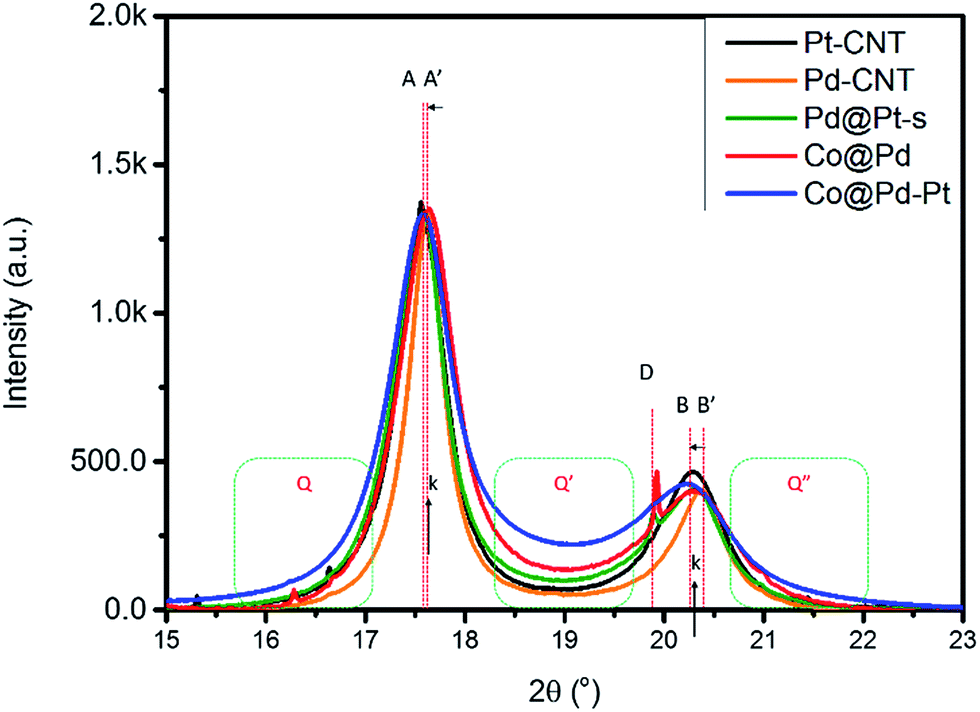 | ||
| Fig. 1 XRD patterns of CNT supported NCs. Pt–CNT and Pd–CNT denote the CNT supported Pt and Pd NCs. Co@Pd denotes the NC in the Co core and Pd shell structure. Pd–Pt and Co@Pd–Pt denote NCs with Pd and Co@Pt cores decorated by Pt atomic clusters. The intensity of the (111) peak for all patterns is normalized to the same value. The asymmetric profiles between peak A and B accompanied by a significant background scattering (Q, Q′ and Q′′) reveal the contribution of the out-of-phase scattering from heterogeneous interfaces between Co, Pd, and Pt domains in Co@Pd–Pt. | ||
The upshift of peak A by 0.015° simultaneously with the downshift of peak B by −0.073° denotes a lattice compression by 0.13% at d(111) and an expansion by 0.41% at d(200) (0.22% at d(220)) as compared to that of Pd–CNT. As consistently explained by DFT model calculation results, lattice compression occurs at the interface between Pt and Co which comes with atomic displacement in the lateral dimension of the (111) slab (i.e., lattice expansion in high index facets, (200) and (220)). A sharp peak at 19.94° denotes the diffraction line of the CoO2 (400) facet (d(400)_CoO2 = 1.991 Å and D(400)_CoO2 = 938.4 Å). Abnormal D(400)_CoO2 indicates a slight amount of rapid oxidation and crystallization of residual Co3+ ions or an insufficient amount of Pd capping matter in the Co core crystal surface. In Co@Pd–Pt, Pt surface modification reinforces the crystallinity of NCs. As compared to the diffraction peak position of the Co@Pd pattern, the position offset of peak A to a low angle is larger than that of peak B. It suggests that the (111) facet possesses a larger amount of the Pt–Pd alloy than the (200) facet in Co@Pd–Pt. In this event, Co@Pd–Pt possesses the highest background in the main peak region among all NCs. The high background scattering refers to substantial out-of-phase scattering from the high roughness NC surface, high local heteroatomic intermix, and coexistence of metal/metal oxide in the shell crystal (which simultaneously reduces the long-term ordering of Pd and Pt crystals) in Co@Pd–Pt.
The surface morphology, atomic structure, and crystal structure of experimental NCs are elucidated by using HRTEM analysis. As demonstrated in Fig. S2,† all control NCs (Pt–CNT and Pd–CNT) are fcc metals and preferentially grown on (111) facets. Variations in NC shape resulted from competitions between factors in the crystal growth rate including surface free energy, surface oxidation, and heteroatomic intermix in different facets. Fig. 2 compares the HRTEM (the line histogram of the selected lattice fringe and low magnification image are compared in the insets) images of Co–CNT, Co@Pd, and Co@Pd–Pt NCs. As indicated in Fig. 2a, a thin nano-flake in the CNT framework is formed in Co–CNT. The formation of such a nano-flake could be accounted for by the agglomeration of poorly crystalline Co oxide and Co metal NCs stacking in a thin sheet of carbon fibre (proved by the electron diffraction pattern in Fig. 2a, the inset and XAS spectra in the Co K-edge in Fig. S3†). Possible pathways include: (1) peeling of a carbon sheet from CNT by interaction between defects and H (released by decomposition of NaBH4) followed by Co2+ reduction to metallic Co clusters by electrons in its surface, (2) oxidation of metallic Co clusters to disordered CoOx, (3) agglomeration of CoOx into a thin sheet of the CoOx/carbon nano-sheet complex, and (4) formation of the CoOx/C nano-flake upon dehydration. In Co@Pd (Fig. 2b), a confinement effect on crystal growth is evident in three aspects. First, highly dispersed NCs are formed with an average particle size of 6.5 nm ± 1.5 nm in CNTs. Compared to the disordered nano-flake structure of Co–CNT, growth of the individual NC depicts the suppression of inter-particle agglomeration due to the presence of heteroatomic structure capping at the CoOx surface. Second, the size of the Co@Pd NC is significantly reduced by 60% (from 8–12 nm to 5–8 nm) as compared to that of the NC in Pd–CNT. This is a typical feature of the heterogeneous surface at the nucleation stage, where a limited amount of Pd ions was fed to grow the Pd shell in the reaction system. In this event, the presence of a self-aligned Pd shell crystal in the Co surface suppresses the crystal growth. Third, a strong lattice mismatch between Co and Pd crystals (∼10%) results in severe atomic displacements (denoted by atomic distance histograms of slices at lattice fringes along (1) and across (2) the mismatched lattices in the white dashed line with double arrows) in multi-facet interfaces ({111} and {220}) in polymorphic crystals. The varied lattice spacing of Pd{111} facets (d(111)_Pd) ranging from 2.248 to 2.284 ± 0.03 Å denotes the formation of incoherent and semi-coherent interfaces demonstrated by distinct differences of local atomic arrangement in various regions (denoted by histograms 1 and 2) of NCs and is consistently explained by the asymmetric diffraction of the peak shape and height in the XRD pattern (Fig. 1) and complex surface chemical species shown by the CV sweep curve (Fig. 5). Compared to Co@Pd, Co@Pd–Pt (Fig. 2c) is characterized by more surface truncations and a smaller particle size by 10 to 15%. The two features reveal relocation of NC surface atoms in two pathways: (1) galvanic replacement between Pt4+ ions and Pd metal atoms and (2) Pt atom deposition at surface defect sites (inter-faceted corner or terraces) of the shell crystal. As compared to d(111)_Co@Pd, d(111)_Co@Pd–Pt is compressed by 1.01% to be 2.264 Å. Such lattice compression explains a strong Pt–Pd bonding at displaced sites of incoherent/semi-coherent interfaces in the Co@Pd substrate. Such a defective interface structure is consistently revealed by Pd K-edge EXAFS analysis (Fig. S3†). As compared to that of Pd–CNT, a substantially smaller total CN of Pd atoms explains the formation of the disordered local structure in the Pd region of Co@Pd. Consequently, the structural reliability of Co@Pd–Pt in a long-term ADT is promised.
 | ||
| Fig. 2 HRTEM images of (a) Co–CNT, (b) Co@Pd, and (c) Co@Pd–Pt. Atomic displacements between lattice fringes are denoted by yellow arrows. Distinct surface truncations (denoted by red dashed lines) elucidate the position of Pt atoms at interfaceted corners or terraces in Co@Pd–Pt. Electron diffraction rings in the inset of (a) are indexed to those of (002), (100), and (103) facets for CNT. | ||
Atomic Pt cluster intercalation induced local atomic structure relocations of NCs
The influences of core crystal structure on atomic and electronic structure of Pt clusters decorating in NC surface is revealed by X-ray absorption spectroscopy analysis. Fig. 3a compares the Pt L3-edge X-ray absorption near-edge spectra (XANES) of NCs under inspection. | ||
| Fig. 3 (a) XANES and (b) Fourier transformed EXAFS spectra of the Co@Pd–Pt NC compared with Pt cluster decorated Co (Co@Pt), Pd (Pd@Pt) NCs and Pt–CNT. | ||
In an L3-edge spectrum, the position of the inflection point (arrow X) refers to the threshold energy (E0) for 2p to 5d electron transition and is linearly proportional to the oxidation state of the target atom (particularly for transition metals). Intensity (ha) and width (WA) of the main peak elucidate the relative extent of empty states and splitting of the 5d5/2 orbital. Width (WB) and intensity (hB) of the post-edge region hump elucidate the extent of structural ordering around the target atom. As can be seen, Pt atoms are in the metallic phase in Pt–CNT, Pd@Pt, and Co@Pd–Pt as illustrated by a similar inflection point position to that of Pt foil (Fig. 3 inset). Compared to Pt foil, a slight increase of ha by ∼2% indicates a considerable extent of oxygen chemisorption due to the absence of the stabilization agent in the Pt–CNT surface. In the meantime, coexistence of metallic Pt and oxygen chemisorbed Pt disorders the surface local structure as revealed by slightly suppressed backscattering intensity in the post-edge region (hB). As for Pd@Pt, compared to the XANES features of Pt–CNT, the identical inflection point position illustrates the metallic state of Pt atoms. Meanwhile, ha is substantially enhanced by ∼15% suggesting that the majority of coordination sites of the Pt atom are occupied by oxygen chemisorption. As consistently illustrated by local atomic structure analysis (Fig. 3b), the high extent of oxygen chemisorption in Pt can be rationalized by the formation of sub-nanometer Pt clusters in the Pd NC surface. In Co@Pd–Pt, reduction of ha explains inhibition of Pt oxidation and the offset of X to the low energy side reveals a charge relocation to Pt from neighbouring atoms due to a slight electronegativity difference and low lattice compression (due to the presence of high density defects in the Pd shell) between Pd and Pt regions. The significant ha attenuation and WB broadening show a severe atomic structure disordering around Pt atoms. Such a hypothesis is clarified by positioning Pt atoms in hollow and defect sites of Pd shell crystals where Pt–Pd distances are determined to be 2.56–2.58 Å as a result of both extended X-ray absorption fine structure (EXAFS) analysis and theoretical DFT calculations. The configuration of Pt atom intercalation in the Pd shell with Pd relocation to the outermost surface in Co@Pd–Pt is further confirmed by enhanced oxygen chemisorption of Pd atoms as compared to that of Pd–CNT (peak H in Fig. S3b†). Local structural information around Co atoms further confirms the proposed nanostructure.
Quantitative atomic structural parameters around Pt and Pd atoms further confirm the nanostructure of experimental NCs. Fig. 3b (Fig. S3b†) shows the Fourier-transformed Pt L3-edge (Pd K-edges) EXAFS spectra (i.e., radial structure functions, RSF) of experimental NCs and structural parameters of model analysis are summarized in Table 2. For RSF of Pt–CNT, the two radial peaks at 1.97 Å (peak C) and 2.74 Å (peak E) respectively account for X-ray interference with bonding of Pt to oxygen and Pt to metallic Pt atoms. The weak peak C (Pt–O bond pair) with a coordination number (CN) of 0.61 suggests that oxygen atoms are bonded in a form of chemisorption at the Pt NC surface. In Pd@Pt RSF, the main radial peak (1.9–3.1 Å) is split into F and G. The split of the metallic RSF peak is a typical feature of destructive interference between outgoing X-ray and both homoatomic Pt–Pt (in a distance of RPt–Pt = 2.747 Å and CNPt–Pt = 2.09) and heteroatomic Pt–Pd (RPt–Pd = 2.731 Å and CNPt–Pd = 1.04) bond pairs in the inhomogeneous alloy (for instance, cluster-in-surface and cluster-in-cluster type) NC.6 Compared with the RSF profiles of experimental NCs, the strongest peak C intensity (CNPt–O = 1.75 and RPt–O = 2.062 Å) indicates the highest extent of Pt oxidation in Pd@Pt. Pt atoms are known to be in metallic states, so a large CNPt–O reveals a severe oxygen chemisorption at Pt clusters located in the near-surface region of the Pd shell. Such a configuration is further confirmed by a smaller total Pt CN (CNtotal_Pt(Pd@Pt) = CNPt–O + CNPt–Pt + CNPt–Pd = 4.88) than total Pd (CNtotal_Pd(Pd@Pt) = CNPd–O + CNPd–Pt + CNPd–Pd = 7.99) in Pd@Pt. Given that CNtotal_Pt(Pd@Pt) (4.88) is substantially smaller than that of atoms in the ideal crystal surface (CNtotal_surface = 6–9 at different facets), a severe oxygen chemisorption in the metallic state explains that Pt clusters are intercalated in the crystal surface and relocate Pd atoms to the outermost region. As a result, a reduced CNtotal_Pd (peak I, Fig. S3†) and CNPd–Oads (peak H, Fig. S3†) as compared to that of Pd–CNT is expectable. For Co@Pt, the main radial peak (peak D) in RSF across 1.7 to 3.2 Å is a contribution to Pt–Pt (RPt–Pt = 2.74 1 Å, CNPt–Pt = 2.63) and Pt–Co (RPt–Co = 2.592 Å, CNPt–Co = 1.98) bond pairs. A high heteroatomic intermix of Co atoms in Pt crystals (χCo–Pt = CNPt–Co/CNtotal_Pt(Co@Pt) = 43.0%, CNtotal_Pt(Co@Pt) = CNPt–Pt + CNPt–Co) depicts a substantial galvanic replacement of Pt4+ + Co0core → Pt0cluster + Co2+ followed by reduction of residual Co2+ and Pt4+ ions (by electrons provided from NaBH4) in the Co crystal surface. These pathways result in a NC comprising the Cocore and Pt rich Co shell. In the absence of CNPt–O, a small CNtotal_Pt (4.61) suggests that Pt atoms tend to form atomic clusters and stack in a highly disordered structure comprising Co, Co oxide, and Co1−xPtx (also proved by suppressed WB in the post-edge region). Compared to that of Co@Pt, a substantial attenuation of peak D intensity by 20.9% with a slight decrease of total CNtotal_Pt(Co@Pd–Pt) (CNPt–Pt + CNPt–Pd + CNPd–Co) by 3% can be rationalized by out-of-phase outgoing X-ray interferences between Pt–Pt (43.5%), Pt–Pd (25.9%), and Pt–Co (30.6%) bond pairs in a local environment with the complex heteroatomic intermix. As consistently explained by HRTEM, the absence of the Pt–O peak and high extent of the Co and Pd intermix reveal that Pt atoms tend to be located in displaced sites of incoherent/semicoherent interfaces to the “heal defective surface” of Co@Pd and formation of Co@Pd–Pt.
| sample | Pt (%) | Pt L3-edge | Pd K-edge | ||||||
|---|---|---|---|---|---|---|---|---|---|
| Bond pair | CN | R | χ | Bond pair | CN | R | χ | ||
| Co@Pt | 4.76 | Pt–Pt | 2.63 | 2.742 | 57.0 | NA | |||
| Pt–Co | 1.98 | 2.593 | 43.0 | ||||||
| Pd@Pt | 4.76 | Pt–O | 1.52 | 1.989 | NA | Pd–O | 0.36 | 2.062 | NA |
| Pt–Pt | 2.09 | 2.747 | 66.8 | Pd–Pd | 5.54 | 2.766 | 72.6 | ||
| Pt–Pd | 1.04 | 2.731 | 33.2 | Pd–Pt | 2.09 | 2.837 | 27.4 | ||
| Co@Pd | 0 | NA | Pd–Pd | 3.81 | 2.741 | 82.1 | |||
| Pd–Co | 0.83 | 2.961 | 17.9 | ||||||
| Co@Pd–Pt | 2.44 | Pt–Pt | 1.95 | 2.691 | 43.5 | Pd–Pd | 6.47 | 2.737 | 80.0 |
| Pt–Pd | 1.16 | 2.671 | 25.9 | Pd–Pt | 0.71 | 2.717 | 8.8 | ||
| Pt–Co | 1.37 | 2.671 | 30.6 | Pd–Co | 0.91 | 2.745 | 11.2 | ||
Atomic Pt cluster induced work function shift and local electron density re-distribution in the near valence band
Work function refers to a potential to be applied for extracting a valence electron to the vacuum level in a material. This value is an index for the activity of a material against redox reaction and can be determined by the position of the secondary cutoff (φ) potential in ultraviolet photoelectron spectroscopy (UPS). Fig. 4 compares the UPS spectra of experimental NCs and the corresponding φ is summarized in Table S1. Accordingly, the φ of experimental NCs follows the trend of Co@Pd–Pt (4.513 eV) < Pd@Pt (4.689 eV) < Pt–CNT (4.743 eV) < Co@Pd (5.003 eV) < Pd–CNT (5.235 eV). Such a trend explains differences of nanostructure, electronic structure, intra-particle heterogeneous interface coherency, oxidation extent, electronegativity of intra-particle domain, and crystal size between NCs. In general, the φ of metallic nanoparticles is smaller than that of the bulk metal and decreases with particle size. For Pd–CNT, a slightly higher φ than that of the Pd metal is a result of competition between the upshift by surface oxidation (PdO = ∼26.9%, determined by XPS in Table S2†) and the downshift by particle size in nanometer (∼7.93 nm). Compared to Pd–CNT, the φ of Co@Pd is reduced by 0.232 eV (5.003 eV). Given that the profile of the UPS spectrum completely differed from that of Co–CNT with prevailing Pd content in the surface (93.4%, Table S2†), Co segregation can be ruled out from an effective factor of φ in Co@Pd. In this event, lattice compression and nano-size effect play a major role in φ. The former increases local electron density in the Pd shell and the latter generates dangling defects in the NC surface.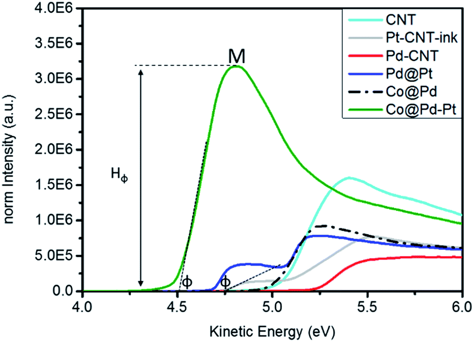 | ||
| Fig. 4 UPS spectra of the Co@Pd–Pt NC compared with Co@Pd, Pd@Pt, and Pd–CNT NCs. The sample of Pt–CNT-ink is a mixture of CNT supported Pt and Nafion. | ||
Both of them extract the electron to the NC surface and thus reduce φ by 0.2 eV as compared to that of metallic Pd. A mixture of Pt–CNT and Nafion slurry (Pt–CNT-ink) possesses a φ of 4.743 eV. This value is 0.377 eV lower than that of metallic Pt (5.12 eV) again rationalizing a nano-size effect on φ reduction. Surface chelation/stabilization by the sulfonyl ligand is a barrier for charge extraction from the NC and increases the φ of Pt–CNT-ink by ∼0.3 eV from the value as it is supposed to be (revealed by φ increment of J.M-Pt by mixing with the Nafion slurry in Fig. S4 and Table S1†). Compared to that of Pd–CNT, the φ of Pd@Pt is further reduced by 0.054 eV. With a similar surface oxidation of Pd (26.9%), a substantial reduction by 0.546 eV explains that local strain and electronegativity difference between Pt and Pd interfaces are dominant factors in NC φ. Co@Pd–Pt possesses a φ of 4.513 eV and is far below that of experimental NCs by 0.17 to 0.71 eV. Compared to that of Co@Pd, a substantial φ reduction is understandable in a NC comprising atomic Pt clusters positioned at the defective Cocore–Pdshell interface. A remarkable intensity (peak M) illustrates an easy electron ejection from the NC surface by inelastic photoelectron scattering and directly proved the electron accumulation by a strong local compression strain at Pt clusters.
Effects of core crystal configuration on the activity and stability of Cocore based ternary NCs in the oxygen reduction reaction
Surface chemical composition of experimental NCs is characterized by using cyclic voltammetry (CV) analysis. These results indicate possible pathways of experimental NCs in the ORR. By cross-referencing structural parameters in all spatial regimes, the exceptional redox durability of experimental NCs in the accelerated degradation test (ADT) with a long-term ORR is explained. Fig. 5 compares the CV curves of experimental NCs with that of the control sample (J.M.-Pt). The CV curves are recorded in an aqueous solution of 0.1 M KOH at room temperature. In general, both CV curves show typical voltammetric behaviour of hydro-reacted species (Pt or Pd) in alkaline media. These behaviours at peak potentials of hydrogen desorption (Ee and Ee′)/adsorption (Ea and Ea′) in the under-potential deposition (UPD) region (region A), formation of an electrical double layer (EDL) by OH-ligand chemisorption (region B), and reduction of chemisorbed oxygen at surface adatoms (at onset potentials of Eoi and Eoii at the forward scan) as well as reduction of alpha Pt or Pd oxides (EPtd or EPdd at the backward scan) (region C) are qualitatively elucidated from the CV curves. Area and features in the UPD H region determined the electrochemical surface area (ECSA) and potential of active facets interacting with proton (H+) in NC surface.7 Profiles in the UPD H region of a CV curve illustrate the responses of low index facets for H+ redox reactions in a NC surface. In this region, the symmetry responses in positive (H+ adsorption peak (e, e′)) and negative (H+ desorption peaks (a, a′)) potential sweeps suggest the growth of a redox stable NC.8 For J.M.-Pt, the position (Ee and Ee′) and intensity (He and He′) of the two characteristic peaks (e and e′) in Fig. 5a denote the potential to be applied for dissociation of H+ from close packed (111) and open ((200) and (220)) facets and corresponding current (reactivity), respectively. The indistinct profiles (peak intensity and position of e/e′ in the forward sweep with respect to a/a′ in the reverse sweep) in region A imply that NCs are grown in isotropic shape (i.e. spherical like) in J.M.-Pt. The presence of the current peak at a potential higher than Eoii (0.71 volt vs. RHE) implies the formation of Pt alpha oxide at inter-facet defects of NCs in J.M.-Pt. Compared to the CV curve profiles of J.M.-Pt, the downshift of all forward redox peaks (e and e′) by different extents accompanied by the upshift of reverse redox counterparts (peaks a and a′) in region A indicates a decrement of the energy barrier for redox desorption/adsorption of H+. As consistently revealed by HRTEM observation (Fig. S2†), a substantially higher intensity of peak e than that of peak e′ reveals a preferential crystal growth on (111) facets in Pt–CNT. Consequently, Pt–CNT possesses lower energy and fewer reaction sites for oxygen adsorption as compared to J.M.-Pt. For Pd–CNT, the smeared CV profile in the UPD H region is due to a high affinity of H+ adsorption and diffusion in the Pd crystal. A profound and narrow EPdd peak resembles the strong affinity with simple pathways for oxygen adsorption in the Pd surface. Such a characteristic implies an easy corrosion of Pd via a reaction of 2Pd + O2 → 2PdO followed by a hydration assisted corrosion in the ORR. The CV curve of the control sample (Co–CNT) is compared with that of Co@Pt in Fig. 5b. Before the hydroxide onset, the absence of reaction peaks in the forward sweep suggests that the surface of the NC is oxygen inactive due to the formation of Co oxide. Consequently, the presence of the asymmetric peak (Y) at 1.15 (volts vs. RHE) denotes the current response from hydration of cobalt oxides (CoOx + H2O + OH− ↔ CoOOH + e−). The absence of the counterpart peak at the reverse sweep suggests that the redox reaction is irreversible for Co–CNT. By adding Pt atoms in the Co–CNT surface (Co@Pt), the Co oxidation peak remained at 1.078 (volts vs. RHE) accompanied by a symmetric peak of O2 adsorption at Pt sites (Pt–Oads2) in its left (1.038 volts) in the forward sweep. In the reverse sweep, the low intensity indistinct oscillation current across a full potential range indicates a set of various pathways with different energy barriers for dissociation of Pt–Oads2 to 2Pt–Oads followed by desorption of Pt–Oadsvia pathways of direct desorption of Pt–Oads from the atop site (Ptad–Oads) and diffusion of Oads to neighbouring positions including hollow sites of Pt–Pt–Pt (Pth3), Pt–Pt–Co (Pt2Coh), and Pt–Co–Co (PtCoh2) bond pairs. As shown in Fig. 5c, the UPD H features of Pd@Pt are further smeared and attenuated as compared to those of Pt–CNT due to the coexistence of Pd and Pt sites for H+ adsorption. Indistinct Eoi and Eoii peaks reveal a suppression of alpha Pt oxides. The upshift and broadening of the Ed peak in the reverse sweep refer respectively to reduction of energy barriers and increase of pathways (i.e., the presence of Ptad, Pth3, Pt2Pdh, and PtPdh2) for Oads desorption from the NC surface. Characteristics mentioned above are attributed to the intrinsic properties of easy oxidation in Pd sites grabbing Oads from Pt in Pd@Pt. | ||
| Fig. 5 CV curves of experimental Co@Pd–Pt compared with that of control samples (Pt–CNT and Pd–CNT) (a) J.M.-Pt, (b) Co–CNT and Co@Pt, (c) Pd@Pt, (d) Co–CNT and Co@Pd, (e) Co@Pd and Co@Pd–Pt at the 1st potential sweep cycle. | ||
Considering the reaction sequences of Co core crystal formation followed by a subsequent heterogeneous crystal growth of Pd with full coverage in its surface, the Co@Pd shell possesses similar features to that of Pd–CNT in a CV curve (Fig. 5d). However, Co@Pd possesses a CV curve with completely different features from those of Pd–CNT and Co–CNT. Such an abnormality in CV explains the complexity of composition and configuration in the NC surface. In the case of bimetallic NC with significant lattice mismatch (ε), incoherent or semi-coherent interfaces are formed between Co and Pd crystals (ε ∼ 10%). Therefore, incomplete Pd coverage with prevailing defects and reaction sites including Pdh3, Coh3, Pd2Coh, and PdCoh2 for adsorption/desorption of oxygen in the NC surface is expectable. Triggered by strong Co oxidation preference, the onsets at 0.236 and 0.642 (volt vs. RHE) can be attributed to alpha oxide formation at PdCoh2 and Pd2Coh, respectively. Similar to redox features of Co@Pt and Co–CNT, the broad peak (Y) refers to an increased energy barrier to hydroxide formation in CoOx due to the presence of Pd around Co sites (i.e., Pd2Coh and PdCoh2) in the Co@Pd surface. In the reverse sweep, broad peaks b and b′ are symmetry counterparts of Eoii and Eoi in the forward sweep (see green double arrows) as a result of oxygen desorption from Pd2Coh and PdCoh2, respectively. In the UPD H region, the absence of redox counterpart peaks (e, e′ and a, a′) could be accounted for by the high affinity of H+ adsorption in a thin Pd and Pd oxide layer that assisted by attraction of CoOx underneath. For Co@Pd–Pt NC (Fig. 5e), as consistently proved by the XPS results, an insignificant Eoi peak in the forward CV curve indicates a suppression of alpha oxide in Pt sites. A broad Eoii peak with onset at 0.58 (volt vs. RHE) is the current response from oxygen adsorption at Pd2Coh followed by oxygen adsorption at Pth3 sites intercalated in Co/Pd (at peak Y) and CoOx hydration at peak X. In the reverse sweep curve, three broad current peaks at 1.12 (Y′) 0.88 (m), and 0.412 (b′′) (volt vs. RHE) are ascribed to oxygen desorption from hollow sites of Pt clusters intercalated in Co (Co@Pth3), Pt–Pd (Pt2Pdh and PtPdh2), and Co rich Pd–Co sites (PdCohR) at the Co–Pd–Pt interface respectively. The absence of proton redox peaks in UPD H elucidates the formation of a NC structure comprising a shell of discrete Pt clusters in an ultra-thin Pd crystal (thinner than ∼2 nm, according to the HRTEM image) and a small Co crystal underneath. The corresponding statements are consistently rationalized by oxygen adsorption energy differences at various sites by using density functional theory (DFT) calculations in the ESI.†
Fig. 6a and b demonstrate the linear sweep voltammetry (LSV) curves and accelerated degradation test (ADT) results of experimental NCs (Co@Pt, Pd@Pt, and Co@Pd–Pt) compared with that of J.M.-Pt in the ORR. To verify the ORR activity of NCs, the LSV curves of Pt–CNT and Pd–CNT are compared in Fig. S6.† These LSV curves are collected in an electrolyte of O2-saturated KOH solution (0.1 M) with a rotation speed of the working electrode fixed at 400–2500 rpm (only the spectra at 1600 rpm are shown and the curves collected at rest of rotation speeds are given in Fig. S6a–f† and the electrochemical properties are summarized in Table 3). Compared with the DFT results (Fig. S5†), the oxygen adsorption energy (Eads) at different heteroatomic sites complementary with the obtained parameters in electrochemical analysis rationalizes the mechanism for ultra-durable NCs with a proper nano-structure in the ORR application. According to Table 3, the Voc of experimental NCs follows the trend of 0.886 volt vs. RHE for Co@Pt, 0.908 volt vs. RHE for Co@Pd, 0.941 volt vs. RHE for Pd@Pt, and 0.937 volt vs. RHE for Co@Pd–Pt. In a LSV curve, Voc refers to the threshold voltage for initiating the ORR in the NC surface. Notice that Pd@Pt shows a 0.019 volt higher Voc (i.e., a lower ORR barrier) as compared to that of J.M.-Pt (0.922 volt vs. RHE). The Voc in a LSV curve is affected by the local environment (composition) of adsorption sites changing with the extent of surface oxidation (shielding effect), heteroatomic intermix (bifunctional mechanism), and identity as well as configuration of intra-particle structures. In general, the surface oxide plays two important roles in affecting the ORR activity: (1) suppression of oxygen adsorption by the steric effect in the NC surface and (2) restructure of transition metals into metal oxides in a highly open NC surface (surface free energy minimization). Both the pathways increase intra-particle resistances and therefore reduce the Voc of NC in the ORR. Increasing the heteroatomic intermix in the near surface region induces electron localization in ORR active sites and electron separation (depletion) in their neighbouring atoms. At active sites (hollow sites of Pt clusters in this study), a strong negative charge field is formed to weaken oxygen adsorption at Pt sites. In neighbouring atoms, a partial positive charge field accompanied by a potential gradient is formed by differences of electronegativity, atomic arrangement (shielding effect), and the extent of oxidation between intra-particle clusters. With a potential gradient, adsorbed oxygen (Oads) at Pt will tend to slide to neighbouring atoms and stay in a kinetically balanced state.
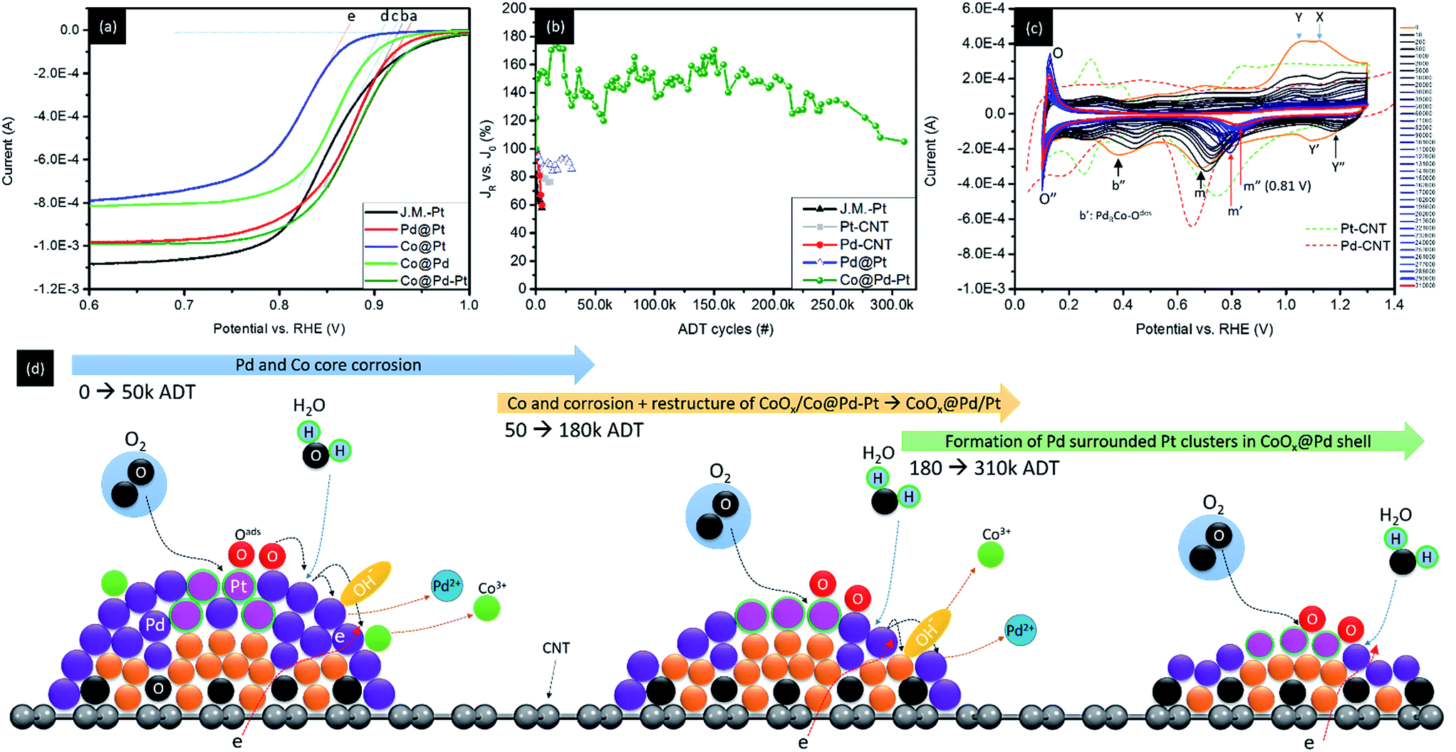 | ||
| Fig. 6 (a) Linear sweep voltammetry (LSV) curve and (b) accelerated degradation test (ADT) results of experimental NCs (Co@Pt, Pd@Pt, and Co@Pd–Pt) compared with that of J.M.-Pt in the ORR. (c) CV curves of Co@Pd–Pt with increasing ADT cycles. (d) Model of atomic structure relocation on Co@Pd–Pt in the ADT from 0 to 310k cycles. | ||
| Sample | V oc 1600 rpm (V) | N (0.5 V) | ECSA_H (m2 g−1) | J k (0.85 V) (mA cm−2) | MAPt (0.85 V) (mA mg−1) | MAtotal (0.85 V) (mA mg−1) | J 0 (mA cm−2) | J R final (mA cm−2) | ΔJ(JR − J0/J0) vs. J0 (%) | ADT cycle (#) |
|---|---|---|---|---|---|---|---|---|---|---|
| J.M.-Pt | 0.922 | 4 | 270.3 | 5.34 | 67.1 | 67.1 | 2.33 | 1.35 | −42.0 | 5000 |
| Pt–CNT | 0.935 | 4.1 | 35.4 | 15.22 | 271.9 | 271.9 | 4.28 | 3.28 | −24.0 | 12![[thin space (1/6-em)]](https://www.rsc.org/images/entities/char_2009.gif) 000 000 |
| Pd–CNT | 0.891 | 5.5 | 51.7 | 14.91 | NA | 32.7 | 1.91 | 1.15 | −40.1 | 5000 |
| Co–CNT | 0.654 | 4 | NA | 2.70 | NA | NA | ||||
| Co@Pt | 0.886 | 3.7 | NA | 2.32 | 134.8 | 134.8 | ||||
| Pd@Pt | 0.941 | 4.1 | 909.4 | 20.08 | 2040.6 | 329.9 | 4.87 | 4.18 | −14.0 | 30000 |
| Co@Pd | 0.908 | 3.3 | 42.0 | 5.15 | NA | 72.2 | ||||
| Co@Pd–Pt | 0.937 | 3.9 | 440.7 | 13.09 | 2056.3 | 172.6 | 2.28 | 2.4 | 5.3 | 310000 |
Given that the surface coverage of Pt is 47.1% in Co@Pd–Pt, a low distance and high frequency relocation pathway for Oads between Pt and Pd sites is expectable. Meanwhile, Pt and Pd prevailing in the surface (Pt = 47.1%, Pd = 49.4%, and Co = 3.5%) evidences the structure of the NC comprising the Pd/Pd rich shell with the Co core underneath. In this event, abundant neighbouring atoms share redox loading from Pt, thus achieving the ultra-durability of Co@Pd–Pt in a long-term ADT for more than 300k cycles in the ORR (Fig. 6b). For Co@Pd, the high interfacial strain between Co and Pd results in high density defects (terrace, step, and vacancy) and complicated heteroatomic sites for Oads (Coh3, Co2Pdh, CoPdh2, and Pdh3) in the NC surface. In the defect region, Oads possesses high adsorption energy at aatom sites. Such a strong bonding of Oads–Maatom leaves a strong strain between the aatoms and the substrate. In heteroatomic sites, strong Eads difference imbalances redox reaction frequency and strength between two metal atoms and Oads. Both the factors strengthen the electrochemical loading of active sites and thus reduce the durability of NCs for the ADT in the ORR.
In Co@Pt and Pd@Pt, shielding and electronic coupling effects of Pt clusters to adjacent domains (Pd and Co core) are relatively lower than those of Co@Pd–Pt. For Pd@Pt, according to the EXAFS fitting results (Table 2), Pt atoms that tend to adsorb in the Pd surface end up with a high density of dangling bonds in their neighbours. In the adsorbed Pt aatom (Ptaatom), the Eads of Oads is 1.5 eV. Such a value is ∼0.45 eV higher than that of neighbouring sites in the NC surface again causing an imbalanced loading effect between Ptaatom and their neighbouring (Pd or Pt) sites. In Pd@Pt, Pt atoms tend to intercalate in open ((200) and (220)) facets where the energy barrier for Oads is relatively lower than that of {111} facets. Therefore, oxidation kinetics and hydration assisted Pd corrosion in the ORR are facilitated. In addition, the charge-transfer-number (n) is 4.6 suggesting a significant amount of intermediates (including H2O2 and O) in the NC surface. These compounds facilitate metal corrosion; consequently, redox durability is reduced due to an exposure of unstable Ptaatom and highly oxygen reduction active species (Pd) to electrolyte in the ORR. Co@Pt shows similar electrochemical responses to Co@Pd in the ORR excepting that Co atoms tend to be oxidized due to insufficient Pt shielding (coverage) in the Co NC surface. In this case, formation of the metal–metal oxide (CoOx) contact weakens the attachment of Pt in the Co oxide core surface, significantly reducing the durability of Co@Pt in the ADT.
To figure out mechanisms for the ultra-fine durability of Co@Pd–Pt in the ADT, CV analysis on its surface chemical composition is conducted at ADT check points (Fig. 6c, measured by each 200 to 2000 ADT cycles) and the corresponding Voc in LSV and the atomic structure relocation model are shown in Fig. S7† and 6d. Compared to CV features of the NC without the ADT (0th), substantially reduced Y and X indicates a dramatic reduction of Co hydride and oxygen adsorption at Pt with increasing ADT cycles. These characteristics resemble a flattening of the NC due to the easy corrosion of defective CoPd composition in the Co@Pd–Pt surface. A significant upshift of peak Y′ to Y′′ refers to the formation of an oxygen inert Pth3 site intercalated at the interface of the Pd shell atop a Co core (PtRCo). Such a feature is ascribed to a strong electronegativity dipole and electronic coupling effect between Pt and Co atoms as a result of Pt cluster relocation to the Co surface via Pd dissolution upon the ADT. Sharp and intense counterpart peaks (O and O′′) in the UPD region are indications of surface redox reactions for H+ in sub-nanometer Pt clusters stacked on top of a thin Pd/Co nanocrystal without high index facets.9 A substantial upshift and attenuation of peaks b′ and b′′ in the reverse sweep curve depict an increasing Pd content in both Pd (PdRCo) and Co rich (PdCoR) sites due to the dissolution of Co from the Co@Pd–Pt NC with increasing ADT cycles. By increasing the number of ADT cycles higher than 50k, the absence of peak b′′ denotes a relocation of Pd to defect sites which reduces Co exposure to the NC surface. In the meantime, peak m is shifted to 0.79 volt vs. RHE (to peak m′) indicating a reduction of oxygen desorption energy by 0.1 volt. Given that Pd atoms tend to relocate to defect sites to flatten the NC surface, such an energy reduction can be attributed to the formation of Pt rich sites at the Co–Pd interface (Pth3). By increasing the ADT cycle higher than 50k, peak m′ is shifted to m′′ (0.81 volt) indicating a further weakening of oxygen desorption energy in the NC surface. As predicted by the DFT calculation results and the presence of atomic Pt clusters in the UPD region, such a feature could be attributed to the formation of a surface structure comprising Pt-clusters with neighbouring Pd atoms and certain layers of Co atoms underneath.
By cross referencing the results of structural characterization, electrochemical analysis, and DFT calculations, the ultra-durability of the ternary Co@Pd–Pt NC in the ORR can be systematically explained by geometric confinement effects in proper nanostructures and the corresponding local redox kinetics balance between active and neighbouring atoms. Details of schematic representation of crystal growth of Co@Pd and Co@Pd–Pt NCs are demonstrated in Scheme 2 and the proposed ORR pathways are shown in Scheme S1.† In the Co@Pd NC, significant lattice mismatch leaves an incoherent interface between Co and Pd regions. Such a highly defective interface possesses complex identity (i.e., Coh3, Co2Pdh, CoPdh2, and Pdh3) and configuration (i.e., dangling bond sites in terrace and step regions) of reaction sites in the NC surface. These reaction sites are kinetically imbalanced in reducing Oads. In this event, the ORR proceeds in the following steps: (1) O2 adsorption in reaction sites in the form of Co3−xPdx–Oads2 (x = 1–3), (2) dissociation of Oads2 into 2Oadsvia Co3−xPdx–Oads2 + Co3−xPdx → 2 Co3−xPdx–Oads, and (3) reduction of Co3−xPdx–Oads into Co3−xPdxvia electrons provided from H2O dissociation or reduction of Co3−xPdx–Oads2 by interaction with Co3−xPdx−H2Oads. Chemisorbed oxygen (Oads) is highly active and will oxidize the low atomic number transition metals (i.e., Pd and Co in this study). Therefore, over stress of the redox reaction occurs in active sites (Pdh3, Co2Pdh, and CoPdh2) and thus reduces the durability of Co@Pd. For Co@Pt, lattice mismatch, oxidation effects, and redox imbalance are even stronger than those in Co@Pd. These phenomena are induced by an insufficient amount of Pt coverage and a preferential formation of homoatomic Pt clusters in highly mismatched Co and CoOx surfaces.10 In terms of crystal growth of Pd@Pt, galvanic replacement upon immersing Pd–CNT in a Pt4+ glycol solution for a limited immersion period (10 s in this study) is suppressed by an insignificant electronegativity difference between Pd and Pt metals. Therefore, by interaction with the reducing agent (NaBH4), Pt atoms tend to locate in adsorption sites (hollow or surface defect sites) and form Pt clusters directly exposing to electrolyte. Given that the intermediate of H2O2 is highly reactive to the Pd metal and Pt–Pd sites at the step as well as the terrace in the NC surface, a corrosion induced current degradation is understandable for Pd@Pt in the ADT. For Co@Pd–Pt, Pt atoms are positioned by adsorbing Pt4+ in defect sites (*) at the Co–Pd interface followed by interaction of these Pt4+_ads-* with the reducing agent. These reaction pathways fix Pt clusters at the Co–Pd interface and, therefore, heal the defective surface into a form of Pt cluster intercalated Co@Pd. In such a surface, electron localization at Pt clusters with potential gradient in their neighbours is formed by lattice strain and electronegativity difference. The slight potential gradient leaves an effective slide for Oads from Pt to Pd sites and electron localization suppresses the adsorption of intermediate species (H2O2, H2O−, and OH−) in the NC surface. These two features protect the NC surface from corrosion, consequently enabling the ultra-durability of Co@Pd–Pt in the ADT for more than 300k cycles in the ORR.
 | ||
| Scheme 2 Schematic representation of crystal growth of Co@Pd and Co@Pd–Pt NCs in sequence controlled self-aligned wet chemical reduction. | ||
Conclusions
Carbon nanotube supported nanocatalysts comprising a Co/CoOx base capped with Pt cluster modified Pd crystals are synthesized by step by step reduction of Co, Pd, and Pt ions by interacting with sodium borohydride in an ethylene glycol solution. Our results show that Co ions will form a highly disordered Co/CoOx layer structure along with a CNT framework. Then the chemisorption of Pd2+ ions on Co/CoOx followed by interaction with H results in Pd capped Co/CoOx NCs (Co@Pd). Positioning and reduction of Pt4+ in Co@Pd result in a ternary NC comprising atomic Pt clusters stacked in the defect region of the core–shell interface (Co@Pd–Pt). We demonstrate that such a Pt decorated Cocore–Pdshell NC achieves ultra-durability in an ADT of the ORR with an impressive mass activity (2056.3 mA mgPt−1 and 172.6 mA mgPd+Pt−1). Such an exceptional stability is ascribed to the formation of an oxygen inert surface comprising Pt3 cluster decorated Pd crystals with Co/CoOx underneath. In such a structure, strong compression strain appears between Pt-to-Pd and Pd-to-Co domains that promotes valence electrons to the near-Fermi level region. This feature triggers a strong surface negative electron field that significantly reduces the work function in this way weakens the oxygen binding energy NC surface. By adopting these characteristics, the MA and ADT durability of NCs in the ORR are substantially enhanced. In the optimal case, the MA for the Pt metal of Co@Pd–Pt is improved ∼30.2-fold as compared to that of J.M.-Pt at 0.85 volt (vs. RHE); meanwhile, no current degradation is found (JR = 105.3% vs. J0) in the ADT for more than 310k cycles. Most importantly, this study provides systematic results of theoretical calculation and structural characterization for developing novel catalysts with a structure of Co/CoOx stack capped with Pt cluster decorated Pd crystals. Such a robust assessment enables the synthesis of NCs with reduced noble metal usage with exceptional stability in cathode devices of future alkaline fuel cell systems.Conflicts of interest
There are no conflicts to declare.Acknowledgements
The authors thank staffs of the National Synchrotron Radiation Research Center (NSRRC), Hsinchu, Taiwan, for helping in various synchrotron-based measurements. The VASP based DFT calculation and the results were conducted by using the clusters at the National Center for High-Performance Computing (NCHC), Taiwan. T.-Y. Chen is thankful for the funding support from the Ministry of Science and Technology, Taiwan (MOST 106-2112-M-007-016-MY3 and MOST 105-3113-E-006-019-CC2). H.-Y. T. Chen is thankful for financial support from MOST106-2112-M-007-001-MY3, Taiwan. AH acknowledges financial support provided by the City University of Hong Kong (Grant No. 9610336) and special thanks to TH2A.Notes and references
- (a) J. Larminie and A. Dicks, Fuel Cell Systems Explained, John Wiley & Sons Ltd, West Sussex PO19 8SQ, England, 2003 Search PubMed; (b) K. Sasaki, H. Naohara, Y. Cai, Y. M. Chio, P. Liu, M. B. Vukmirovic, J. X. Wang and R. R. Adzic, Angew. Chem., Int. Ed., 2010, 49, 8602 CrossRef CAS PubMed; (c) M. P. Hoh and T. R. Ralph, Platinum Met. Rev., 2002, 46, 117 Search PubMed.
- (a) S.-Y. Huang, C. M. Chang, K. W. Wang and C.-T. Yeh, ChemPhysChem, 2007, 8, 1774 CrossRef CAS PubMed; (b) R. R. Adzic, J. Zhang, K. Sasaki, M. B. Vukmirovic, M. Shao, J. X. Wang, A. U. Nilekar, M. Mavrikakis, J. A. Valerio and F. Uribe, Top. Catal., 2007, 46, 249 CrossRef CAS; (c) F. Besenbacher, I. Chorkendorff, B. S. Clausen, B. Hammer, A. M. Molenbroek, J. K. Nørskov and I. Stensgaard, Science, 1998, 279, 1913 CrossRef CAS PubMed; (d) F. Liu, J. Y. Lee and W. J. Zhou, Small, 2006, 2, 121 CrossRef CAS PubMed; (e) J. Greeley and M. Mavrikakis, Nat. Mater., 2004, 3, 810 CrossRef CAS PubMed; (f) S. Alayoglu, A. U. Nilekar, M. Mavrikakis and B. Eichhorn, Nat. Mater., 2008, 7, 333 CrossRef CAS PubMed; (g) P. Strasser, S. Koh, T. Anniyev, J. Greeley, K. More, C. Yu, Z. Liu, S. Kaya, D. Nordlund, H. Ogasawara, M. F. Toney and A. Nilsson, Nat. Chem., 2010, 2, 454 CrossRef CAS PubMed.
- (a) T. Bligaard and J. K. Nørskov, Electrochim. Acta, 2007, 52, 5512 CrossRef CAS; (b) T.-Y. Chen, H.-D. Li, G.-W. Lee, P.-C. Huang, P.-W. Yang, Y.-T. Liu, Y.-F. Liao, H.-T. Jeng, D.-S. Lin and T.-L. Lin, Phys. Chem. Chem. Phys., 2015, 17, 15131 RSC; (c) A. Schlapka, M. Lischka, A. Gross, U. Kasberger and P. Jakob, Phys. Rev. Lett., 2003, 91, 016101 CrossRef CAS PubMed.
- (a) B. J. Hwang, L. S. Sarma, J. M. Chen, C. H. Chen, S. C. Shih, G. R. Wang, D. G. Liu, J. F. Lee and M. T. Tang, J. Am. Chem. Soc., 2005, 127, 11140 CrossRef CAS PubMed; (b) Y. Ding, X. Sun, Z. L. Wang and S. Sun, Appl. Phys. Lett., 2012, 100, 111603 CrossRef.
- (a) C.-J. Powell and A. Jablonski, NIST electron effective attenuation-length database Version 1.2, Gaithersburg, 2001 Search PubMed; (b) M. P. Seah and W. A. Dench, Surf. Interface Anal., 1979, 1, 2 CrossRef CAS; (c) N. J. Divins, I. Angurell, C. Escudero, V. Pérez-Dieste and J. Llorca, Science, 2014, 346, 620 CrossRef CAS PubMed; (d) S. Ghosal, J. C. Hemminger, H. Bluhm, B. S. Mun, E. L. D. Hebenstreit, G. Ketteler, D. F. Ogletree, F. G. Requejo and M. Salmeron, Science, 2005, 307, 563 CrossRef CAS PubMed.
- H. M. Barkholtz, J. R. Gallagher, T. Li, Y. Liu, R. E. Winans, J. T. Miller, D.-J. Liu and T. Xu, Chem. Mater., 2016, 28, 2267 CrossRef CAS.
- (a) C.-C. Hu and K.-Y. Liu, Electrochim. Acta, 1999, 44, 2727 CrossRef CAS; (b) C.-C. Hu and K.-Y. Liu, Electrochim. Acta, 2000, 45, 3063 Search PubMed.
- T.-Y. Chen, Y.-T. Liu, H.-S. Chen, K.-W. Wang, C.-T. Yang, T.-J. M. Luo, C.-H. Lee and T.-L. Lin, CrystEngComm, 2013, 15, 3932 RSC.
- T. Yang, G. Cao, Q. Huang, Y. Ma, S. Wan, H. Zhao, N. Li, X. Sun and F. Yin, ACS Appl. Mater. Interfaces, 2015, 7, 17162 CAS.
- (a) L. Vitos, A. V. Ruban, H. L. Skriver and J. Kollár, Surf. Sci., 1998, 411, 186 CrossRef CAS; (b) S. Nakatsuji, V. Dobrosavljević, D. Tanasković, M. Minakata, H. Fukazawa and Y. Maeno, Phys. Rev. Lett., 2004, 93, 146401 CrossRef CAS PubMed.
Footnote |
| † Electronic supplementary information (ESI) available. See DOI: 10.1039/c7se00532f |
| This journal is © The Royal Society of Chemistry 2018 |