
 Open Access Article
 This Open Access Article is licensed under a Creative Commons Attribution-Non Commercial 3.0 Unported Licence
A bimetallic oxide Fe1.89Mo4.11O7 electrocatalyst with highly efficient hydrogen evolution reaction activity in alkaline and acidic media†
Zhaomin
Hao
 a,
Shishuai
Yang
a,
Jingyang
Niu
a,
Zhiqiang
Fang
a,
Liangliang
Liu
b,
Qingsong
Dong
*a,
Shuyan
Song
c and
Yong
Zhao
*b
a,
Shishuai
Yang
a,
Jingyang
Niu
a,
Zhiqiang
Fang
a,
Liangliang
Liu
b,
Qingsong
Dong
*a,
Shuyan
Song
c and
Yong
Zhao
*b
aHenan Key Laboratory of Polyoxometalate Chemistry, College of Chemistry and Chemical Engineering, Henan University, Kaifeng, 475004, Henan Province, P. R. China. E-mail: zmhao@henu.edu.cn
bKey Lab for Special Functional Materials of Ministry of Education, Collaborative Innovation Center of Nano Functional Materials and Applications, Henan University, Kaifeng, 475004, Henan Province, P. R. China. E-mail: zhaoyong@henu.edu.cn
cState Key Laboratory of Rare Earth Resource Utilization, Changchun Institute of Applied Chemistry, Chinese Academy of Sciences, Changchun 130022, P. R. China
First published on 28th May 2018
Abstract
Transition-metal Mo-based materials have been considered to be among the most effective hydrogen evolution reaction (HER) electrocatalysts. Regulating the electronic structure of Mo atoms with guest metal atoms is considered as one of the important strategies to improve their HER activity. However, introduction of guest metal elements in the vicinity of Mo sites with atomic-level hybridization is difficult to realize, resulting in the failure of the modified electronic structure of Mo sites. Herein, an Fe1.89Mo4.11O7/MoO2 material is prepared through the thermal treatment of a ferrimolybdate precursor. It exhibits a Tafel slope of 79 mV dec−1 and an exchange current density of 0.069 mA cm−2 in 1 M KOH medium, as well as a Tafel slope of 47 mV dec−1 and an exchange current density of 0.072 mA cm−2 in 0.5 M H2SO4 medium. Compared to original Mo-based oxides, Fe1.89Mo4.11O7 with the regulated Mo electronic structure shows a more suitable Mo–H bond strength for the fast kinetics of the HER process. Density functional theory (DFT) calculations also indicate that the Mo–H bond strength in Fe1.89Mo4.11O7 is similar to the Pt–H bond strength, resulting in the high kinetic activity of Mo-based HER electrocatalysts in alkaline and acidic media.
Introduction
Electrolysis of water is an important component of hydrogen manufacturing technologies that can tackle the intense challenge of depletion of fossil fuels and increased environmental concerns.1–3 The hydrogen evolution reaction (HER) is the essential reaction in water electrolysis, and requires an effective electrocatalyst to decrease the reaction energy barrier and increase the energy conversion efficiency.4 Many research studies have already shown that Pt and its alloys are the best electrocatalysts due to their fast and stable reaction kinetics, but their high cost and scarcity limit their widespread application.5 Great efforts have been devoted to the design and synthesis of alternative HER electrocatalysts based on cheap and earth-abundant metal elements, such as non-precious metal oxides (e.g. NiO and Mo–W18O49), carbides (e.g. WC and Mo2C), phosphides (e.g. CoP, MoP and FeP), sulfides (e.g. Ni3S2 and MoS2), etc.6 Among all of these alternatives, transition-metal Mo-based materials are some of the most efficient HER electrocatalysts to date. In the family of Mo-based materials, molybdenum carbides, nitrides, sulfides and oxides are reported to be efficient and stable HER catalysts.7 To achieve good HER activity of Mo-based catalysts, two types of strategies are often proposed: (1) improving the density of Mo active sites (Dcas), and (2) increasing the effective surface area (Seff). For instance, our group prepared a MoCN nanocatalyst by using an in situ CO2 emission strategy and the abundant amino group-based polydiaminopyridine precursors, which substantially improved the Dcas of Mo.8 Chen et al. fabricated a NiMoNx/C electrocatalyst by nitridation of NiMo bimetals with ammonia gas, demonstrating that the imprinting of NiMo nanopowders on high-surface-area carbon nanoparticles could largely improve the Seff.9Apart from the two strategies mentioned above, regulating the electronic structure (Es) of Mo atoms is another important strategy to improve the HER activity of Mo-based catalysts. Introduction of guest non-metal or metal atoms can meet this demand. It potentially achieves a suitable metal–hydrogen bond strength between the Mo active site and hydrogen intermediates, resulting in the increased HER activity of Mo-based catalysts.10 However, introduction of guest metal elements in the vicinity of Mo sites is difficult to realize to achieve the atomic-level hybridization of Mo and other metals.7c This is due to the fact that the starting precursors in the reported strategies are always based on the hybridization of Mo-based salt with other metal salts in the micro-sized state. Pyrolyzing such precursors can't produce a good dispersion of guest metal atoms in the Mo-based catalysts, resulting in the failure of the electronic structure of Mo active sites. Doping non-metal elements seems to be more controllable to modulate the electronic structure of Mo sites compared to those of metal atoms.7b However, non-metal atoms could potentially be removed from Mo sites under environmental conditions. For example, neither MoC nor MoN is stable enough in oxygen-containing environments or alkaline medium, and molybdenum oxides will cover the material surface.9,10 Therefore, most of the materials still possess high HER overpotentials, thus impeding further improvement of their electrocatalytic activity.
In this work, an Fe1.89Mo4.11O7 electrocatalyst was prepared by the thermal treatment of a ferrimolybdate precursor, an organic–inorganic compound which was synthesized by the self-assembly of Fe3+ and polymolybdate species. By using the ferrimolybdate as a precursor, the introduction of transition metal Fe atoms in the vicinity of Mo atoms at the atomic scale was realized in the Fe1.89Mo4.11O7 based material. Compared to original Mo-based oxides, the modified electronic structure of Mo in Fe1.89Mo4.11O7 induced the optimized metal–hydrogen bond strength. As a result, the kinetic activity was greatly improved with this type of Mo-based catalyst. Moreover, the HER activity of the as-prepared Fe1.89Mo4.11O7/MoO2 was much better than that of an Fe/MoO2 electrocatalyst synthesized by pyrolyzing the hybrid of Fe3+ and a polymolybdate precursor. Theoretical calculations further confirmed that Fe-coordinated Mo sites did help to regulate the electronic structure of Mo active sites, which was beneficial for enhancing the HER activity of Mo-based catalysts.
Results and discussion
Fig. 1 shows the synthesis protocol for the preparation of different Mo-based materials. For obtaining the atom-scale blended Fe–Mo oxide (namely Fe1.89Mo4.11O7/MoO2), Fe-containing ferrimolybdate molecules ([Fe(phen)2(H2O)]2[PMo12O40])11 (single crystals) were used as a precursor, which was treated via carburization and self-reduction reactions (producing low valence Mo),12 followed by etching the unstable and inactive species from the pyrolyzed sample in 0.5 M H2SO4 solution to get the Fe1.89Mo4.11O7/MoO2 material. As a reference sample, a MoO2 material without Fe was synthesized by using a similar polymolybdate (without Fe3+, [phen]3[PMo12O40]) as a precursor following the same pyrolysis protocol. Moreover, another reference sample, a non-atom-scale blended Fe–Mo oxide (named Fe/MoO2), was synthesized by pyrolyzing the hybrid precursor of FeCl3 and the polymolybdate ([phen]3[PMo12O40]) to clarify the influence of Fe-coordination on the HER activity of Mo sites. Scheme S1† shows the chemical structure of polymolybdates and ferrimolybdates with Keggin anions and organic ligands (phenanthroline). Most of the organic components in the hybrid of Fe3+ and polymolybdates ultimately transformed into CO2 when the pyrolysis temperature was above 600 °C. The transformation of ferrimolybdates required a higher temperature (about 800 °C) to achieve the same results (Fig. S1†). The differences of thermogravimetric temperatures in the hybrid of Fe3+ and polymolybdates, and ferrimolybdates for carbon element probably played an important role in carburization reactions.7a Using the hybrid of Fe3+ and polymolybdates as the precursor, Fe and Mo could not be in the atom-scale blended state and the self-reduction reaction was difficult to realize during the thermal treatment of FeCl3 and polymolybdates.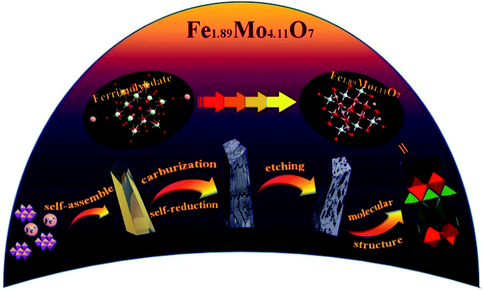 | ||
| Fig. 1 Schematic illustration of the formation of Fe1.89Mo4.11O7. | ||
The morphologies of the as-prepared Mo-based materials were checked by performing field-emission scanning electron microscopy (SEM) and transmission electron microscopy (TEM). Fig. 2a and b show the SEM images of the ferrimolybdate precursor and Fe1.89Mo4.11O7/MoO2 sample, indicating that they are basically massive structures. The SEM image in the inset of Fig. 2a demonstrates that the surface of the as-prepared ferrimolybdate precursor is roughly smooth, which is attributed to its single crystal properties. The SEM image of Fe1.89Mo4.11O7/MoO2 shows that the surface of the Mo-based oxide is changed to a coarse and loose structure. Energy-dispersive X-ray (EDX) elemental mapping images based on an individual crystal particle confirm the coexistence and uniform distribution of Fe and Mo elements within the Fe1.89Mo4.11O7/MoO2 sample (Fig. S2†). From the high resolution TEM (HRTEM) image (Fig. 2c and S4†), the lattice spacing is about 0.481 nm, matching well with the (100) planes of the rhombohedral hexagonal phase of MoO2. Moreover, the estimated lattice spacing of 0.257 nm can be indexed to the (121) planes of Fe1.89Mo4.11O7. Importantly, the well-defined diffraction rings in the selected-area electron diffraction (SAED) pattern (Fig. 2d) confirm the polycrystalline nature of MoO2 and Fe1.89Mo4.11O7. These rings can be well indexed to the (310) and (200) planes of MoO2 and the (105) and (022) crystal planes of Fe1.89Mo4.11O7. All of the measurements confirmed that the Fe1.89Mo4.11O7 material was successfully prepared using our synthesis protocol.
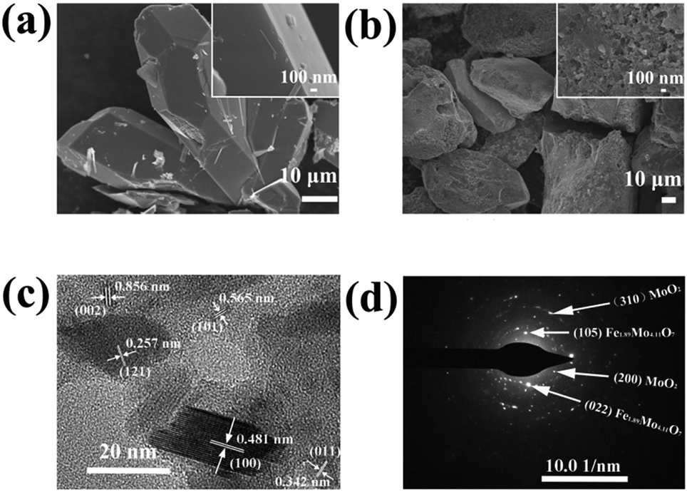 | ||
| Fig. 2 SEM images of (a) the ferrimolybdate precursor and (b) the synthesized Fe1.89Mo4.11O7/MoO2 sample, and (c) HRTEM image and (d) SAED pattern of the Fe1.89Mo4.11O7/MoO2 sample. | ||
The crystalline structure of the as-synthesized products was checked by analyzing their powder X-ray diffraction (XRD) patterns. As shown in Fig. 3a, the XRD pattern of the Fe1.89Mo4.11O7/MoO2 material contains peaks of Fe1.89Mo4.11O7 and MoO2 (JSPCD no. 42-0317 and 73-1249). The characteristic diffraction peaks at 10.3, 15.7, 30.2 and 43.6 can be indexed to the (002), (101), (105) and (220) planes of Fe1.89Mo4.11O7. The diffraction peaks at 18.4, 26.0, 31.8, 36.9, 53.5 and 63.5 can be indexed to the (100), (011), (−102), (−211), (−311) and (−123) planes of the MoO2 crystal structure. In comparison, no diffraction peaks of Fe1.89Mo4.11O7 are observed in the XRD patterns of MoO2 and Fe/MoO2 samples, and only MoO2 peaks appear. This indicates that the ferrimolybdate is essential for the synthesis of the Fe1.89Mo4.11O7 component in the Fe1.89Mo4.11O7/MoO2 material.
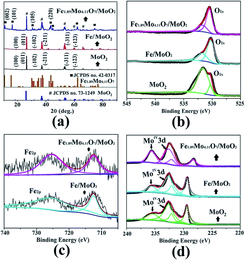 | ||
| Fig. 3 The patterns of Fe1.89Mo4.11O7/MoO2, Fe/MoO2 and MoO2 (a) for XRD and XPS (b) O1s, (c) Fe2p, and (d) Mo3d. | ||
X-ray photoelectron spectroscopy (XPS) measurements were used to check the surface composition of our synthesized samples including that of MoO2, MoO2/Fe and Fe1.89Mo4.11O7/MoO2. The binding energies centred at 530.4 and 531.6 eV are ascribed to O1s,12 while the binding energies of Fe2p are located at 710.7 and 724 eV with a valence state of +313 (Fig. 3b and c). It is notable that the peak shape change for O1s is due to the introduction of Fe element. Owing to pyrolyzing the organic–inorganic compound of ferrimolybdate in an Ar atmosphere, a C1s peak centred at 284.3 eV can be detected. In the Fe1.89Mo4.11O7/MoO2 material, a small amount of carbon (5.3%) acted as a catalyst support owing to its good electrical conductivity (no molybdenum carbide is detected in the XRD pattern). To determine the composition of Fe1.89Mo4.11O7/MoO2, the peaks of Mo3d were compared with those of MoO2 and MoO2/Fe. Compared to original Mo-based oxides, the introduction of Fe atoms can induce changes in electronegativity and modify the electronic structure of Mo. As shown in Fig. 3d, not only are the peak shapes very distinctive for Fe1.89Mo4.11O7/MoO2, but the position of some peaks is also shifted. The right peak in Mo3d is shifted negatively by about 1.1 eV in comparison with those of MoO2 and MoO2/Fe samples. This indicates that the chemical environment of Mo is changed because of atom-scale blended Fe–Mo, and the electron density of Mo sites is enriched. This is proposed to be beneficial for the optimization of Mo–H bond strength in the HER process.
The electrocatalytic HER activity of the as-prepared Mo-based materials was evaluated in both alkaline and acidic aqueous solutions (pH 0.3 and pH 13.6). The HER activity of the Fe1.89Mo4.11O7/MoO2 catalyst was firstly optimized by pyrolyzing the precursors at different temperatures. As shown in Fig. S7,† the Fe1.89Mo4.11O7/MoO2 catalyst prepared at 1000 °C has the best performance, while the other samples show slightly inferior HER activity. Thus, all of the Mo-based catalysts prepared at 1000 °C are used for comparison of their HER activity. The Fe1.89Mo4.11O7/MoO2 catalyst shows an onset potential as low as ∼70 mV in alkaline medium (pH 13.6) and ∼40 mV in acidic medium (pH 0.3), which are estimated from the low current density region of the Tafel plot (Fig. S9 and S10†).14Fig. 4a and b show the electrocatalytic properties of HER catalysts under alkaline and acidic conditions, respectively. An overpotential of 197 mV is required for the Fe1.89Mo4.11O7/MoO2 catalyst to achieve a current density of 10 mA cm−2 in 1 M KOH. This value is much lower than those of the bare carbon paste (514 mV for 10 mA cm−2), MoO2 (431 mV for 10 mA cm−2) and Fe/MoO2 (322 mV for 10 mA cm−2) samples (Fig. 4c and Table S1†). In addition, the electrocatalytic kinetics for the HER was analyzed using Tafel plots. As shown in Fig. S11,† the Fe1.89Mo4.11O7/MoO2 catalyst exhibits a small Tafel slope of 79 mV dec−1, higher than 52 mV dec−1 for the 20% Pt/C catalyst. By extrapolating the Tafel plots, the value of exchange current density for the Fe1.89Mo4.11O7/MoO2 catalyst is calculated to be 0.069 mA cm−2 (Fig. S12†). In acidic electrolyte, it can be seen that the Fe1.89Mo4.11O7/MoO2 catalyst requires an overpotential of 125 mV to drive a current density of 10 mA cm−2 (Fig. 4c). The overpotential is much smaller than those of carbon paste (321 mV), MoO2 (318 mV) and Fe/MoO2 (194 mV) (Table S1†). As the sample composition has a significant effect on HER performance, XPS measurements were taken to check the fraction of each phase on the surface. In the Fe1.89Mo4.11O7/MoO2 sample, the atomic percentage of Fe is calculated to be 2.73%. Accordingly, the content of pure Fe1.89Mo4.11O7 and MoO2 is 15.8% and 78.9% in the mixture of Fe1.89Mo4.11O7/MoO2, respectively. When the Fe1.89Mo4.11O7/MoO2 sample was further etched by Ar sputtering at 1 Å s−1 for 100 s, there was no obvious change in the atomic percentage of Fe (2.65%, within a reasonable error range). This is due to the fact that Fe element is uniformly distributed in the Fe1.89Mo4.11O7/MoO2 product, which is deduced from the good distribution of Fe atoms at the atomic scale in the [Fe(phen)2(H2O)]2[PMo12O40] precursor. For the Fe1.89Mo4.11O7/MoO2 catalyst, a 15.8% content of Fe1.89Mo4.11O7 results in a substantially decreased HER overpotential, leading to superior HER activity for Fe1.89Mo4.11O7. The low HER overpotential at a current density of 10 mA cm−2 for the Fe1.89Mo4.11O7/MoO2 catalyst is also comparable to the values reported for most Mo-related HER catalysts in acidic aqueous media, such as MoS2/RGO (140 mV for 10 mA cm−2), MoO3/MoS2 (250 mV for 10 mA cm−2), MoSe2/Mo (166 mV for 10 mA cm−2), etc.15 (Table S2†). Similarly, the Tafel plots depicted in Fig. S12† also show a small Tafel slope of 47 mV dec−1 for the Fe1.89Mo4.11O7/MoO2 catalyst in 0.5 M H2SO4, along with an exchange current density of ∼0.072 mA cm−2 (Fig. S14†).
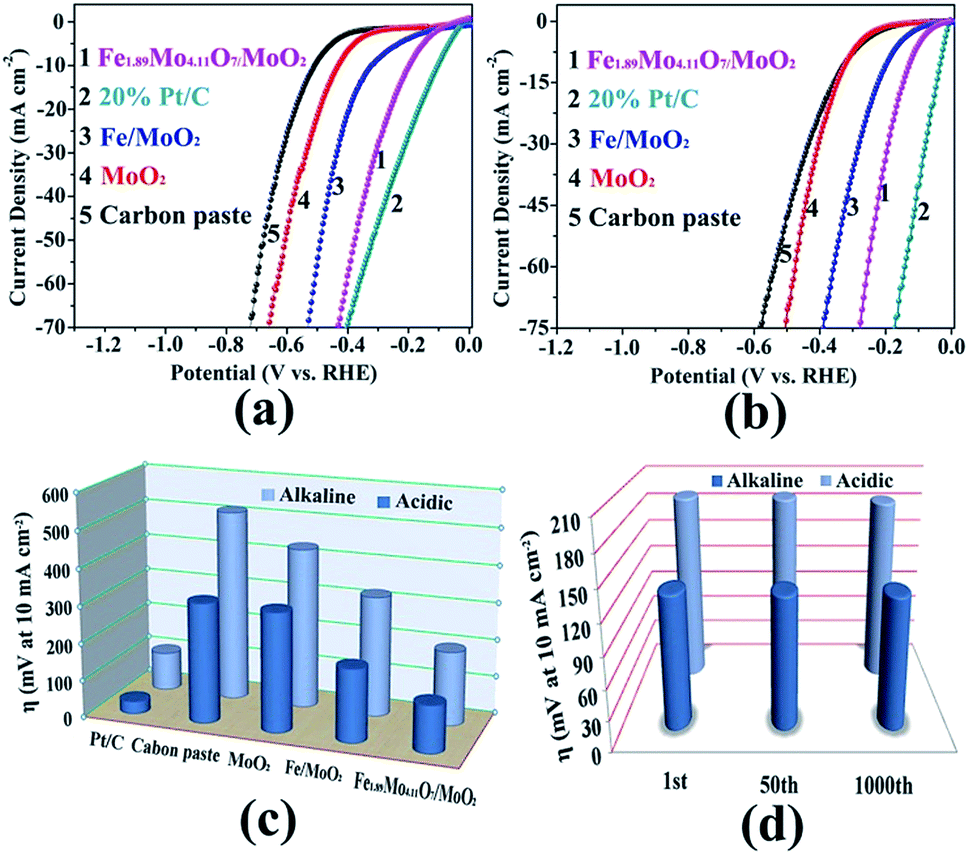 | ||
| Fig. 4 HER performance of the Mo-based catalysts. (a) Polarization curves in 1 M KOH (pH 13.6), (b) polarization curves in 0.5 M H2SO4 (pH 0.3), (c) the HER activities expressed as potentials required to achieve a current density of 10 mA cm−2, and (d) the changes at the current density of 10 mA cm−2 during continuous potential sweeps. | ||
To assess the durability of the Fe1.89Mo4.11O7/MoO2 electrocatalyst, linear potential sweeps were conducted at a scan rate of 20 mV s−1 in acidic and alkaline media. As shown in Fig. 4d and S15,† the polarization curve displays no shift during the first 50 sweeps at 10 mA cm−2 in both alkaline and acidic aqueous solutions. After continuous scanning for 1000 cycles, the polarization curves show only a little shift at a current density of 10 mA cm−2, indicating that Fe1.89Mo4.11O7/MoO2 is stable over a wide pH range. The i–t measurements reveal that the Fe1.89Mo4.11O7/MoO2 electrocatalyst can maintain good catalytic activity in alkaline solution for at least 25 h (Fig. S16†). In order to clarify the stability of Fe1.89Mo4.11O7/MoO2 before and after hydrolysis, we checked its morphology by performing TEM measurements (Fig. S17†). No change of Fe1.89Mo4.11O7/MoO2 can be found. This demonstrates the good stability of the Fe1.89Mo4.11O7/MoO2 electrode for the HER in both alkaline and acidic environments.
To gain insight into the electrocatalytic activity of Fe1.89Mo4.11O7/MoO2, the HER curves are normalized by the amount of active sites and specific surface areas. According to the XPS results, the ratio of the Mo content on the surface of MoO2, Fe/MoO2 and Fe1.89Mo4.11O7/MoO2 is about 1![[thin space (1/6-em)]](https://www.rsc.org/images/entities/char_2009.gif) :1:0.75. After normalizing the HER current densities based on Mo content, Fe1.89Mo4.11O7/MoO2 still shows better electrocatalytic activity than those of MoO2 and Fe/MoO2 materials (Fig. 5a). Based on the results of Brunauer–Emmett–Teller (BET) analysis, the specific surface areas of Fe/MoO2 and Fe1.89Mo4.11O7/MoO2 are 22.8 m2 g−1 and 45.5 m2 g−1, respectively (Fig. 5b). When the HER curves are normalized by BET surface areas, the difference in the electrocatalytic activity between Fe/MoO2 and Fe1.89Mo4.11O7/MoO2 is narrow but the absolute high-low tendency isn't changed (Fig. 5b). This indicates that the kinetic activity of Mo sites in Fe1.89Mo4.11O7 is much higher than in MoO2 and Fe/MoO2 materials.
:1:0.75. After normalizing the HER current densities based on Mo content, Fe1.89Mo4.11O7/MoO2 still shows better electrocatalytic activity than those of MoO2 and Fe/MoO2 materials (Fig. 5a). Based on the results of Brunauer–Emmett–Teller (BET) analysis, the specific surface areas of Fe/MoO2 and Fe1.89Mo4.11O7/MoO2 are 22.8 m2 g−1 and 45.5 m2 g−1, respectively (Fig. 5b). When the HER curves are normalized by BET surface areas, the difference in the electrocatalytic activity between Fe/MoO2 and Fe1.89Mo4.11O7/MoO2 is narrow but the absolute high-low tendency isn't changed (Fig. 5b). This indicates that the kinetic activity of Mo sites in Fe1.89Mo4.11O7 is much higher than in MoO2 and Fe/MoO2 materials.
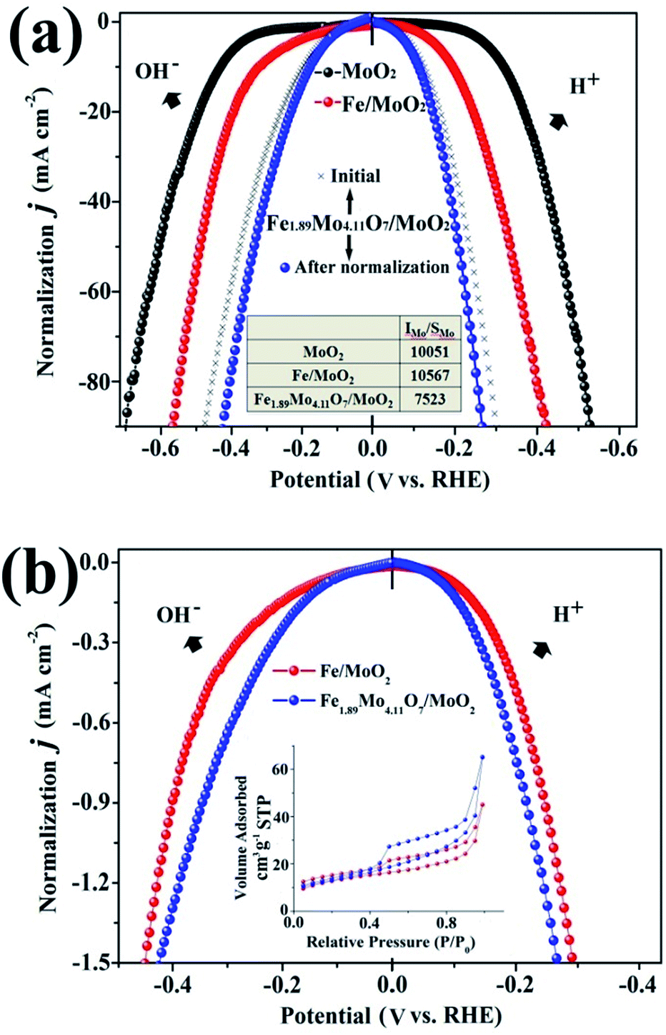 | ||
| Fig. 5 The HER curves normalized by (a) active sites (based on Mo) and (b) specific surface areas. | ||
To further clarify the nature of the high HER activity of Mo sites in Fe1.89Mo4.11O7, density functional theory (DFT) calculation using the Vienna Ab initio Simulation Package (VASP) was employed to understand the origin of the HER activity of the Fe1.89Mo4.11O7/MoO2 catalyst. It was already demonstrated that a good HER catalyst should have moderate metal–hydrogen bond strength.16 Neither strong nor weak binding conditions of hydrogen intermediates would be beneficial for the overall HER reaction with a fast reaction rate, because the strong or weak binding conditions lead to either difficulty in removing the final product (H2) or poor adsorption of the reactant (H+). Herein, the metal–hydrogen (M–H) bond strength in Fe1.89Mo4.11O7 is calculated to compare the Mo active sites with those in other representative Mo-based oxides. As shown in Fig. S18,† there is a distinct difference between the Fe–H and the Mo–H bond strength in Fe1.89Mo4.11O7. The Mo–H bond strength (309 kJ mol−1) in Fe1.89Mo4.11O7 is closer to the Pt–H bond strength, while the Fe–H bond strength (916 kJ mol−1) deviates from the Pt–H bond strength greatly, suggesting that Mo atoms serve as active sites in Fe1.89Mo4.11O7. In addition, the metal–hydrogen bond strength of Fe1.89Mo4.11O7 is also different from those of MoO2 (24 kJ mol−1), Mo5O14 (206 kJ mol−1) and Mo8O23 (428 kJ mol−1) (Fig. 6), indicating that the introduction of Fe in the vicinity of Mo sites indeed regulates the electronic structure of molybdenum active sites, resulting in a highly efficient Mo-based catalyst. As is well established, Pt is considered as one of the most excellent electrocatalysts for fast reaction kinetics. As shown in Fig. 6, the Mo–H bond strength in Fe1.89Mo4.11O7 is closer to the Pt–H bond strength compared to other Mo-based oxides, suggesting that Fe1.89Mo4.11O7 has more effective Mo active sites.
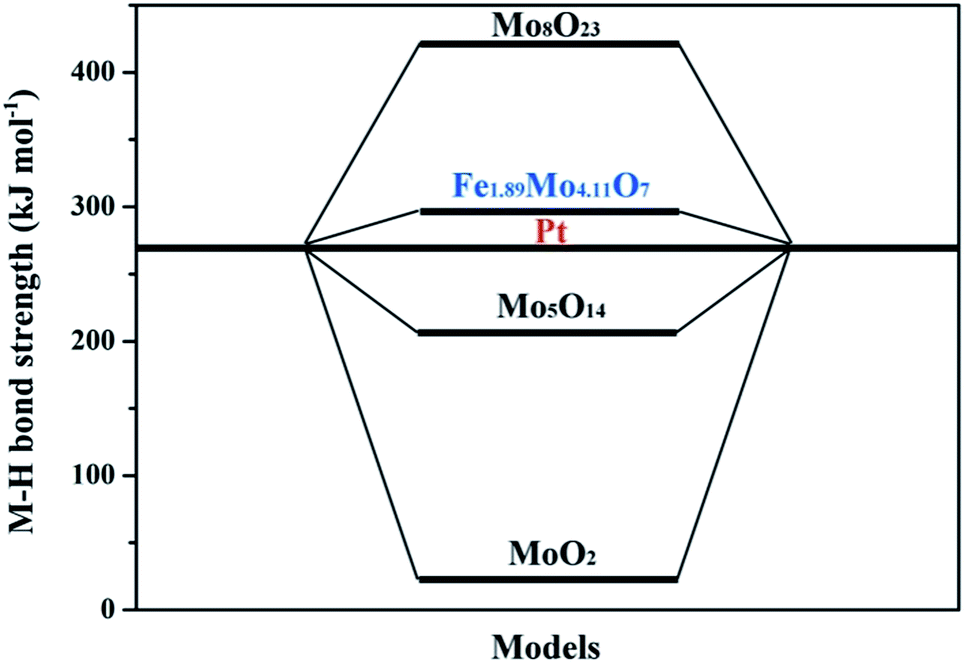 | ||
| Fig. 6 The density functional theory (DFT) calculation of the metal–hydrogen (M–H) bond strength of the representative Mo-based oxides and Pt. | ||
Conclusions and outlook
In summary, a novel binary Fe1.89Mo4.11O7 electrocatalyst was prepared by the thermal treatment of a ferrimolybdate organic–inorganic hybrid. Benefiting from the modified electronic structure of Mo sites, the Fe1.89Mo4.11O7/MoO2 material showed highly efficient HER activity in both alkaline and acidic media. Further work on improving the purity of Fe1.89Mo4.11O7 will substantially improve the HER activity from the viewpoint of active site enrichment. This work has profound experimental and theoretical significance in the field of polyoxometals and their applications, and it will inspire rational creation of new binary Mo-related oxides for advanced electrocatalytic hydrogen production.Conflicts of interest
The authors declare no conflicts of interest.Acknowledgements
The authors are grateful to the financial support from the National Natural Science Foundation of China (No. 21401203, 21702045, U1604122, 21773055 and 51702086), the Education Department of Henan Province (Grant 15A150035), Program for Science & Technology Innovation Talents in Universities of Henan Province (18HASTIT004), and the “1000 Youth Talents Plan” of China.Notes and references
- (a) A. J. Bard and M. A. Fox, Acc. Chem. Res., 1995, 28, 141–145 CrossRef; (b) J. Chow, R. J. Kopp and P. R. Portney, Science, 2003, 302, 1528–1531 CrossRef PubMed.
- (a) H. Zhong, J. Wang, F. Meng and X. Zhang, Angew. Chem., Int. Ed., 2016, 55, 10091–10095 CrossRef; (b) N. S. Lewis and D. G. Nocera, Proc. Natl. Acad. Sci. U. S. A., 2006, 103, 15729–15735 CrossRef PubMed; (c) J. Sun, H. Yin, P. Liu, Y. Wang, X. Yao, Z. Tang and H. Zhao, Chem. Sci., 2016, 7, 5640–5646 RSC; (d) S. Zhao, Y. Wang, J. Dong, C.-T. He, H. Yin, P. An, K. Zhao, X. Zhang, C. Gao, L. Zhang, J. Lv, J. Wang, J. Zhang, A. M. Khattak, N. A. Khan, Z. Wei, J. Zhang, S. Liu, H. Zhao and Z. Tang, Nat. Energy, 2016, 1, 16184–16194 CrossRef.
- (a) Z. Lu, M. Sun, T. Xu, Y. Li, W. Xu, Z. Chang, Y. Ding, X. Sun and L. Jiang, Adv. Mater., 2015, 27, 2361–2366 CrossRef PubMed; (b) R. C. Dustin, D. M. Aditya, M. G. Alejandro, M. Ulises, S. Andriy and J. Zhang, Nat. Commun., 2016, 7, 11857–11867 CrossRef PubMed; (c) Y. Shi, J. Wang, C. Wang, T. T. Zhai, W. J. Bao, J. J. Xu and X. H. Xia, J. Am. Chem. Soc., 2015, 137, 7365–7370 CrossRef PubMed; (d) H. Yin and Z. Tang, Chem. Soc. Rev., 2016, 45, 4873–4891 RSC.
- (a) M. G. Walter, E. L. Warren, J. R. McKone, S. W. Boettcher, Q. Mi, E. A. Santori and N. S. Lewis, Chem. Rev., 2010, 110, 6446–6473 CrossRef PubMed; (b) H. Yin, S. Zhao, K. Zhao, A. Muqsit, H. Tang, L. Chang, H. Zhao, Y. Gao and Z. Tang, Nat. Commun., 2015, 6, 6430–6438 CrossRef PubMed.
- S. Zhang, Y. Z. Hao, D. Su, V. V. T. Doan-Nguyen, Y. T. Wu, J. Li, S. Sun and C. B. Murray, J. Am. Chem. Soc., 2014, 136, 15921–15924 CrossRef PubMed.
- (a) Y. Xu, M. Gao, Y. Zheng, J. Jiang and S. Yu, Angew. Chem., Int. Ed., 2013, 52, 8546–8550 CrossRef PubMed; (b) J. Yang, D. Voiry, S. J. Ahn, D. Kang, A. Y. Kim, M. Chhowalla and H. S. Shin, Angew. Chem., Int. Ed., 2013, 52, 13751–13754 CrossRef PubMed; (c) Z. Lu, W. Zhu, X. Yu, H. Zhang, Y. Li, X. Sun, X. Wang, H. Wang, J. Wang, J. Luo, X. Lei and L. Jiang, Adv. Mater., 2014, 26, 2683–2687 CrossRef PubMed; (d) C. G. Morales-Guio and X. Hu, Acc. Chem. Res., 2014, 47, 2671–2681 CrossRef PubMed; (e) D. Kong, H. Wang, Z. Lu and Y. Cui, J. Am. Chem. Soc., 2014, 136, 4897–4900 CrossRef PubMed; (f) L. Liao, S. Wang, J. Xiao, X. Bian, Y. Zhang, M. D. Scanlon, X. Hu, Y. Tang, B. Liu and H. H. Girault, Energy Environ. Sci., 2014, 7, 387–392 RSC; (g) Q. Liu, J. Tian, A. M. Asiri and X. Sun, Angew. Chem., Int. Ed., 2014, 53, 6828–6832 CrossRef; (h) P. Jiang, Q. Liu, Y. Liang, J. Tian, A. M. Asiri and X. Sun, Angew. Chem., Int. Ed., 2014, 53, 12855–12859 CrossRef PubMed; (i) E. J. Popczun, C. G. Read, C. W. Roske, N. S. Lewis and R. E. Schaak, Angew. Chem., Int. Ed., 2014, 53, 5531–5534 CrossRef; (j) P. Xiao, X. Ge, H. Wang, Z. Liu, A. Fisher and X. Wang, Adv. Funct. Mater., 2015, 25, 1520–1526 CrossRef; (k) H. Tang, J. Wang, H. Yin, H. Zhao, D. Wang and Z. Tang, Adv. Mater., 2015, 27, 1117–1123 CrossRef PubMed; (l) L. Han, S. Dong and E. Wang, Adv. Mater., 2016, 28, 9266–9291 CrossRef PubMed; (m) C. L. Bentley, M. Kang, F. M. Maddar, F. Li, M. Walker, J. Zhang and P. R. Unwin, Chem. Sci., 2017, 8, 6583–6593 RSC.
- (a) H. B. Wu, B. Y. Xia, L. Yu, X.-Y. Yu and X. W. Lou, Nat. Commun., 2015, 6, 6512–6519 CrossRef PubMed; (b) W.-F. Chen, C.-H. Wang, K. Sasaki, N. Marinkovic, W. Xu, J. T. Muckerman, Y. Zhu and R. R. Adzic, Energy Environ. Sci., 2013, 6, 943–951 RSC; (c) X. Xu, F. Nosheen and X. Wang, Chem. Mater., 2016, 28, 6313–6320 CrossRef; (d) X. Xie, L. Lin, R. Liu, Y. Jiang, Q. Zhu and A. Xu, J. Mater. Chem. A, 2015, 3, 8055–8061 RSC; (e) X. Xie, R. Yu, N. Xue, A. B. Yousaf, H. Du, K. Liang, N. Jiang and A. Xu, J. Mater. Chem. A, 2016, 4, 1647–1652 RSC; (f) L. Yang, W. Zhou, D. Hou, K. Zhou, G. Li, Z. Tang, L. Li and S. Chen, Nanoscale, 2015, 7, 5203–5208 RSC; (g) Y. Jin and P. K. Shen, J. Mater. Chem. A, 2015, 3, 20080–20085 RSC; (h) Y. Jin, H. Wang, J. Li, X. Yue, Y. Han, P. K. Shen and Y. Cui, Adv. Mater., 2016, 28, 3785–3790 CrossRef PubMed; (i) L. Wu, X. Wang, Y. Sun, Y. Liu and J. Li, Nanoscale, 2015, 7, 7040–7044 RSC; (j) J.-S. Li, Y. Wang, C.-H. Liu, S.-L. Li, Y.-G. Wang, L.-Z. Dong, Z.-H. Dai, Y.-F. Li and Y.-Q. Lan, Nat. Commun., 2016, 7, 11204–11211 CrossRef PubMed.
- Y. Zhao, K. Kamiya, K. Hashimoto and S. Nakanishi, J. Am. Chem. Soc., 2015, 137, 110–113 CrossRef PubMed.
- W. F. Chen, K. Sasaki, C. Ma, A. I. Frenkel, N. Marinkovic, J. T. Muckerman, Y. M. Zhu and R. R. Adzic, Angew. Chem., Int. Ed., 2012, 51, 6131–6135 CrossRef PubMed.
- M.-R. Gao, M. K. Y. Chan and Y. Sun, Nat. Commun., 2015, 6, 7493–7501 CrossRef PubMed.
- (a) J. Q. Sha, J. Peng, H. S. Liu, J. Chen, A. X. Tian, B. X. Dong and P. P. Zhang, J. Coord. Chem., 2008, 61, 1221–1233 CrossRef; (b) Q. Zhang and C. Tian, Chem. Bull., 2011, 74, 942–946 Search PubMed.
- (a) J. Haber, T. Machej, L. Ungier and J. Ziolkowski, J. Solid State Chem., 1978, 25, 207–218 CrossRef; (b) T. A. Patterson, J. C. Carver, D. E. Leyden and D. M. Hercules, J. Phys. Chem., 1976, 80, 1700–1708 CrossRef.
- (a) H. J. Mathieu and D. Landolt, Corros. Sci., 1986, 26, 547–559 CrossRef; (b) B. J. Tan, K. J. Klabunde and P. M. A. Sherwood, Chem. Mater., 1990, 2, 186–191 CrossRef.
- W. F. Chen, K. Sasaki, C. Ma, A. I. Frenkel, N. Marinkovic, J. T. Muckerman, Y. Zhu and R. R. Adzic, Angew. Chem., Int. Ed., 2012, 51, 6131–6135 CrossRef PubMed.
- (a) J. Kibsgaard, Z. B. Chen, B. N. Reinecke and T. F. Jaramillo, Nat. Mater., 2012, 11, 963–969 CrossRef PubMed; (b) M.-R. Gao, J.-X. Liang, Y.-R. Xu, J. Jiang, Q. Gao, J. Li and S.-H. Yu, Nat. Commun., 2015, 6, 5982–5989 CrossRef PubMed; (c) D. Voiry, H. Yamaguchi, J. Li, R. Silva, D. C. B. Alves, T. Fujita, M. Chen, T. Asefa, V. B. Shenoy and G. Eda, Nat. Mater., 2013, 12, 850–855 CrossRef PubMed; (d) Z. Chen, D. Cummins, B. N. Reinecke, E. Clark, M. K. Sunkara and T. F. Jaramillo, Nano Lett., 2011, 11, 4168–4175 CrossRef PubMed; (e) Y. Li, H. Wang, L. Xie, Y. Liang, G. Hong and H. Dai, J. Am. Chem. Soc., 2011, 133, 7296–7299 CrossRef PubMed; (f) H. Lin, Z. Shi, S. He, X. Yu, S. Wang, Q. Gao and Y. Tang, Chem. Sci., 2016, 7, 3399–3405 RSC; (g) Y. Qu, H. Medina, S. W. Wang, Y. C. Wang, C. W. Chen, T. Y. Chen, A. Manikandan, K. Wang, Y. C. Shi, J. W. Chang, H. C. Kuo, C. Y. Lee, S. Y. Lu, G. Shen, Z. M. Wang and Y. L. Chueh, Adv. Mater., 2016, 28, 9831–9838 CrossRef PubMed.
- (a) B. E. Conway and G. Jerkiewicz, Electrochim. Acta, 2000, 45, 4075–4083 CrossRef; (b) F. Calle-Vallejo, M. T. M. Kopera and A. S. Bandarenka, Chem. Soc. Rev., 2013, 42, 5210–5230 RSC.
Footnote |
| † Electronic supplementary information (ESI) available: Experimental details, TG, EDX, additional XPS results, SEM, TEM, related electrochemical curves, comparison of the HER performance with that of other HER electrocatalysts and related DFT details. See DOI: 10.1039/c8sc01710g |
| This journal is © The Royal Society of Chemistry 2018 |