
 Open Access Article
 This Open Access Article is licensed under a Creative Commons Attribution-Non Commercial 3.0 Unported Licence
Similar ligand–metal bonding for transition metals and actinides? 5f1 U(C7H7)2−versus 3dn metallocenes†
Dumitru-Claudiu
Sergentu
 ,
Frédéric
Gendron
and
Jochen
Autschbach
*
,
Frédéric
Gendron
and
Jochen
Autschbach
*
Department of Chemistry, University at Buffalo, State University of New York, Buffalo, NY 14260-3000, USA. E-mail: jochena@buffalo.edu
First published on 11th June 2018
Abstract
U(C7H7)2− is a fascinating 5f1 complex whose metal–ligand bonding was assigned in the literature as being very similar to 3d7 cobaltocene, based on a crystal-field theoretical interpretation of the experimental magnetic resonance data. The present work provides an in-depth theoretical study of the electronic structure, bonding, and magnetic properties of the 5f1 U(C7H7)2−vs. 3d metallocenes with V, Co, and Ni, performed with relativistic wavefunction and density functional methods. The ligand to metal donation bonding in U(C7H7)2− is strong and in fact similar to that in vanadocene, in the sense that the highest occupied arene orbitals donate electron density into empty metal orbitals of the same symmetry with respect to the rotational axis (3dπ for V, 5fδ for U), but selectively with α spin (↑). For Co and Ni, the dative bonding from the ligands is β spin (↓) selective into partially filled 3dπ orbitals. In all systems, this spin delocalization triggers spin polarization in the arene σ bonding framework, causing proton spin densities opposite to those of the carbons. As a consequence, the proton spin densities and hyperfine coupling constants  are negative for the Co and Ni complex, but positive for vanadocene. The
  of U(C7H7)2− is negative and similar to that of cobaltocene, but only because of the strong spin–orbit coupling in the actinocene, which causes
  to be opposite to the sign of the proton spin density. The study contributes to a better understanding of actinide 5f vs. transition metal 3d covalency, and highlights potential pitfalls when interpreting experimental magnetic resonance data in terms of covalent bonding for actinide complexes.
1 Introduction
Metal sandwich complexes are an important class of organometallic compounds and have attracted the attention of theoreticians and experimentalists for many decades.1–4 These compounds feature a metal center between two (nearly) parallel arene ligands, usually in highly symmetric structures. The metal ion can be a low oxidation-state transition metal (TM), a lanthanide (Ln), or an actinide (An). Common metallocenes are the TM(C5H5)2, where a TM2+ ion is sandwiched between two cyclopentadienyl ligands. This series debuted with the discovery of ferrocene (TM = Fe)5–8 in the 1950s, and new members were synthesized soon after. Common lanthanocenes and actinocenes are the bis[8]annulene complexes M(C8H8)2 (M = Ac or Ln).9–15 Cerocene (Ln = Ce) and uranocene (Ac = U) are two well-studied examples from these series, the former because of the mixed-valence oxidation state of the Ce center (III+ vs. IV+),16–21 and the later because of the central role that U plays in the development of organoactinide chemistry.15,22–25 The set of known U-based sandwich complexes also includes the unusual U(C7H7)2− (a uranocene analogue).26–28 It has been debated whether the oxidation state of U in this compound is +III or +V. The +V oxidation state corresponds to U-5f1 and is supported by magnetic measurements and crystal-field (CF) analyses,27,28 while a III+ oxidation state corresponds to U-5f3 and can be justified by the strong metal–ligand bonding in the complex.28 Therefore, the metal center in U(C7H7)2− can be regarded as formally 5f3 UIII, or 5f1 UV with substantial ligand to metal donation bonding. We note that the assigned formal oxidation state and the actual metal charge may be different.The lanthanocenes and actinocenes are of fundamental interest in chemistry, because of the varying degree of the involvement of the heavy metal orbitals in bonding interactions via their 4f–5d and 5f–6d shells, respectively.15,24,29–32 It is important to distinguish the symmetry of the frontier arene π orbitals with respect to the principal symmetry axis of the sandwich compound. In the following, we use subscripts σ, π, δ, ϕ for |m![[small script l]](https://www.rsc.org/images/entities/char_e146.gif) | = 0, 1, 2, 3, such that, for instance, πδ denotes a π orbital of an arene ligand that has a δ nodal pattern with respect to the principal axis of the complex and can overlap with a metal 3dδ or 5fδ orbital.
| = 0, 1, 2, 3, such that, for instance, πδ denotes a π orbital of an arene ligand that has a δ nodal pattern with respect to the principal axis of the complex and can overlap with a metal 3dδ or 5fδ orbital.
Metal–ligand interactions are already complex in TM metallocenes, as evidenced in early studies,1,33–40 and perhaps even more so in actinocenes.24,30,31 The complexity arises from a number of factors: ligand-to-metal (L–M) donation and metal-to-ligand (M–L) back-donation may take place, the L–M and M–L interactions may have preference for α spin (↑) over β spin (↓), or vice versa, if the metal ion has unpaired spins, valence electrons may be distributed among d and/or f metal-centered orbitals such that multi-configurational electronic ground-states (GSs) and low-energy excited states (ESs) arise, and there may be non-vanishing orbital angular momenta in addition to the electron spin angular momenta. The picture gets complicated further by spin polarization effects, and by relativistic effects. Spin–orbit coupling (SOC), in particular, becomes very large in actinide complexes while at the same time the comparatively large radial extension of the An 5f shell gives rise to a 5f ligand field (LF) that is much stronger than for the lanthanide 4f shell. As a consequence, for actinides, 5f, along with 6d and 7s, may participate in covalent bonding.31 The complicated interplay of these interactions renders experimental magnetic resonance data, for instance, difficult to interpret without theoretical support.
Interestingly, there are experimental findings that point to rather similar ligand–metal bonding in the aforementioned systems U(C7H7)2− and Co(C5H5)2. In the remainder of this work, U(C7H7)2− will be considered to exhibit a 5f1 metal center to underline the metal unpaired 5f electron count. In any case, the assigned formal metal oxidation state, being either III or V, has no bearing on the actual electron (spin) density in U(C7H7)2−. In a seminal article, Gourier et al.27 reported experimental condensed-phase magnetic resonance data for U(C7H7)2−. Based on a CF model, Gourier et al. predicted g factors in agreement with the experiment and concluded that the GS of U(C7H7)2− is predominantly 5fπ in character (51.4%) with an important admixture of 5fσ (38.5%), as dictated by the combined influence of SOC and CF effects, and minor contributions from 5fϕ and 5fδ. A sizable negative isotropic 1H hyperfine coupling constant (HyFCC),  , was interpreted as indicating negative spin density, i.e. an excess of β-spin (↓) versus α-spin (↑) density, at the arene protons in U(C7H7)2−, triggered by a positive spin density (excess ↑) at the C centers and the McConnell spin polarization mechanism.34 In turn, the positive carbon spin density was thought to be caused by β-spin donation from the arene πσ and ππ orbitals into the half-filled U orbitals of mixed 5fσ–5fπ character. On the basis of the sign and magnitude of
  and estimated spin density of ρα–β ≥ 0.036 in the individual C2pz orbitals, and their similarity with cobaltocene (
 and ρα–β ≥ 0.078),41 Gourier et al. concluded that extensive covalent ligand–metal bonding must be present in U(C7H7)2−, and that it is similar to the bonding Co(C5H5)2 as far as the spin density is concerned.
The apparent similarity of the metal–ligand bonding in these two systems is very intriguing, because the interaction between the Co 3d and U 5f orbitals with the ligand orbitals is expected to be quite different already at the scalar relativistic (SR) level of theory,28,29,41i.e. without considering SOC. For instance, the highest occupied arene frontier orbital, interacting most strongly with the metal, is ππ for C5H5− but πδ for C7H73−, as correctly noted by Gourier et al. The SOC is expected to complicate the bonding picture for the U(C7H7)2− further, while it does not play a significant role for cobaltocene or other TM metallocenes. The overall spin density distribution in the two sandwich complexes, and the underlying bonding mechanisms, may therefore be very different. This would mean, however, that a similar  for cobaltocene and the 5f1 U(C7H7)2− is caused by a mechanism that was not taken into consideration previously. For instance, the observed sign for the
  may also be due to the PSO mechanism (paramagnetic interaction of the nuclear spin with the electron orbital angular momentum). PSO contributes to the hyperfine coupling when there is an electron orbital angular momentum. The latter may arise from spatial degeneracies, from the SOC, or a combination thereof. For details on the PSO and other mechanisms that influence the HyFCCs, we refer the reader to a selection of specialized articles.42–48
Herein, the electronic structures, the chemical bonding, and the magnetic properties (g factors, 13C and 1H HyFCCs), in U(C7H7)2− and TM(C5H5)2 with TM = V, Co, and Ni are studied in detail with relativistic density functional theory (DFT) and multiconfigurational wavefunction methods. We specifically chose these three TM systems for comparison with the U(C7H7)2− because they show distinct L–M and M–L interactions that translate into distinct magnetic properties.42,49–52 It is shown that the L–M bonding in U(C7H7)2− is in fact quite similar to that in vanadocene, triggering positive spin densities at the ligand protons. However, when SOC is accounted for, the proton HyFCC in U(C7H7)2− has a negative sign and is similar in value to that of cobaltocene, even though cobaltocene has negative spin density at the protons and different ligand to metal donation bonding. The findings suggest that a spin–orbit induced PSO mechanism is crucial and determines the sign of the proton HyFCC in U(C7H7)2−.
2 Computational details
Equilibrium geometries for the TM(C5H5)2, TM = V, Co, Ni, and U(C7H7)2− systems were obtained by SR-DFT employing the Amsterdam Density Functional (ADF) package53 and the zeroth order regular approximation (ZORA) all-electron relativistic Hamiltonian.54 For the D5h structure of Co(C5H5)2 and an excited state of U(C7H7)2−, the DFT calculations were performed using an ‘average-of-configuration’ (AOC) fractional orbital occupation scheme to avoid symmetry breaking. Different exchange–correlation functionals, namely the BP55,56 and PBE57,58 generalized gradient approximations (GGAs) and the B3LYP59–61 and PBE0![[thin space (1/6-em)]](https://www.rsc.org/images/entities/char_2009.gif) 62,63 hybrid GGAs, were used in conjunction with all-electron doubly-polarized triple-ζ (TZ2P) Slater-type basis sets.64 Additional details of the electronic structures, e.g. orbital occupations, atomic spin densities, were explored via natural bond orbital (NBO) calculations.65 Similar calculations were also carried at the eclipsed (D8h) experimental structure with standard C–H bond lengths, of U(C8H8) (5f2 uranocene),13,14 in order to make comparisons with the 5f1 U(C7H7)2−. If not indicated otherwise, plots of orbital isosurfaces correspond to AOC spin-restricted open-shell calculations with a common set of α spin (↑) and β spin (↓) orbitals, while spin density plots and numerical spin populations are based on spin-unrestricted DFT calculations with separate sets of α and β spin orbitals.
62,63 hybrid GGAs, were used in conjunction with all-electron doubly-polarized triple-ζ (TZ2P) Slater-type basis sets.64 Additional details of the electronic structures, e.g. orbital occupations, atomic spin densities, were explored via natural bond orbital (NBO) calculations.65 Similar calculations were also carried at the eclipsed (D8h) experimental structure with standard C–H bond lengths, of U(C8H8) (5f2 uranocene),13,14 in order to make comparisons with the 5f1 U(C7H7)2−. If not indicated otherwise, plots of orbital isosurfaces correspond to AOC spin-restricted open-shell calculations with a common set of α spin (↑) and β spin (↓) orbitals, while spin density plots and numerical spin populations are based on spin-unrestricted DFT calculations with separate sets of α and β spin orbitals.
With DFT, magnetic properties (g factors,  and
and  ) were calculated using the NMR,66,67 CPL68–70 and ESR71,72 modules of ADF. In the NMR and CPL modules, the effect of SOC on the g and A matrices is introduced via perturbation theory on top of SR-ZORA ground states. In the ESR module, the effect of SOC is treated self-consistently via the use of the two-component relativistic spin–orbit (SO) ZORA Hamiltonian (SO-ZORA). For metallocenes, the SO-ZORA calculations used a spin-unrestricted formalism with collinear spin densities, to allow for spin-polarization effects in the computation of the g factors or HyFCCs, which are important for strong metal–ligand covalency. For U(C7H7)2−, the g factors and HyFCCs were also calculated within a SO-ZORA approach that makes use of a spin-restricted formalism. Although this restricted formalism does not allow for the evaluation of spin polarization effects, it properly imposes Kramers symmetry, which is more important for this system governed by strong SOC. The aforementioned density functionals were used in the magnetic-property calculations, in conjunction with a quadruply-polarized quadruple-ζ (QZ4P) Slater-type basis set for the metal,64 and the ‘jcpl’ augmented version of TZ2P for C and H.73
Ab initio wave function calculations were performed using the Molcas software74 (pre v8.1 developers' version). The complete active space self-consistent field method (CASSCF)75 was used to introduce mostly static correlation. Dynamic correlation was treated by complete active space perturbation theory at second order (CASPT2).76 The PT2 calculations used an imaginary shift of 0.2 and an ionization potential electron affinity shift of zero. SR effects were treated via the second-order Douglas–Kroll–Hess Hamiltonian77–80 in conjunction with all-electron atomic natural orbital relativistically contracted basis sets of polarized valence triple-ζ quality (ANO-RCC-VTZP).81–83 Various active spaces (nel, morb), with nel being the number of active electrons and morb number of active orbitals, were considered for the different complexes as detailed in Section S2 of the ESI.† Additional spin-polarization effects were introduced through the restricted active space configuration interaction approach (RASCI) following a scheme analyzed by Suaud et al.84 (ESI, Section S2†). RASCI was previously used to treat a limited extent of spin polarization in actinide complexes.44,45,85
SOC was treated in a configuration interaction fashion using the restricted active space state interaction (RASSI) module86 of Molcas. In this approach, a state-interaction matrix is constructed in the basis of the spin components of the SR CASSCF states, the diagonal elements being either CASSCF or CASPT2 energies, and off-diagonal SOC matrix elements are computed within a mean-field approximation.87 All SOC calculations were followed by computations of g factors using the approach described in ref. 88 and implemented in the RASSI module of Molcas. For brevity, SR/SOC CASSCF and CASPT2 is referred as CAS-SR/CAS-SO and PT2-SR/PT2-SO in the following.
3 Results and discussion
3.1 Equilibrium structures and ground electronic spin-states
The structures of the complexes are shown in Fig. 1. As the structural features of the 3d metallocenes, and the question of an eclipsed vs. staggered conformation, are well known, details regarding the structure optimizations and experimental data can be found in the ESI.† For the bonding analyses and the magnetic property calculations in this study, optimized D5h eclipsed conformers with a five-fold rotational axis of symmetry were used for the metallocenes with V and Ni. The 3d orbital degeneracy of the metal ions is lifted by the axial LF into a 3dσ ( in D5h) and twofold degenerate 3dδ (
 ) and 3dπ (
 ) orbitals. For vanadocene, V2+ (3d3), the shell filling gives rise to a CF (3dσ)1(3dδ)2(3dπ)0 configuration and a spin-quartet
  GS. For nickelocene, Ni2+ (3d8), the CF configuration is (3dσ)2(3dδ)4(3dπ)2 and the GS is a spin-triplet
  . Note that the 3d-shell occupations are confirmed by experiments for both vanadocene89–91 and nickelocene.89,90,92
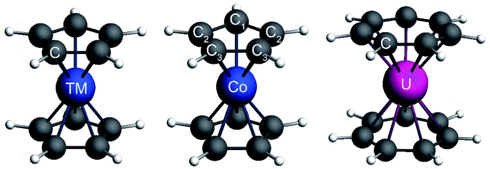 | ||
| Fig. 1 Balls & sticks representations of the optimized structures of V and Ni metallocene (left), Co(C5H5)2 (center, JT distorted structure), and the averaged XRD structure of U(C7H7)2− (right). Light grey corresponds to hydrogen atoms. | ||
Cobaltocene affords a Co2+ (3d7) ion with a formal (3dσ)2(3dδ)4(3dπ)1 CF configuration.90,93 The unpaired electron in the degenerate 3dπ orbitals leads to an orbitally degenerate spin-doublet GS,  in D5h symmetry. Jahn–Teller (JT) distortions94,95 remove the orbital-degeneracy by symmetry lowering to C2v, leading to a spin-doublet GS of 2B1 symmetry.49,93,96 The structure affords three types of symmetry-unique C atoms (Fig. 1), which are on average ∼2.10 Å away from the Co center (BP/TZ2P, Table S1†). Irrespective of the used functional, the structural parameters of the optimized JT geometry are similar to the ones found for the five-fold symmetric structures because the magnitude of the JT distortion is small. The optimized BP/TZ2P C2v JT structure was used for subsequent calculations, unless specified otherwise.
For U(C7H7)2−, the axial LF lifts the 5f degeneracy into a 5fσ ( in the D7h eclipsed structure), and pairs of twofold degenerate 5fϕ (
 ), 5fπ (
 ) and 5fδ (
 ) orbitals. In a SR theoretical description, the unpaired electron occupies the 5fσ orbital, giving rise to a spin-doublet electronic GS of
  .28 The optimized SR geometry (see Table S1†) is in good agreement with the experimental condensed phase X-ray diffraction (XRD) data. This suggests that structural changes due to SOC are insignificant. The SR GS of U(C7H7)2− is orbitally non-degenerate and therefore it does not undergo JT distortions. On experimental grounds however, due to crystal packing, the solid state structure exhibits a lower C2h symmetry,26 with U–C distances that agree within 0.1 Å. Since the distortion is small, a D7h geometry with averaged experimental U–C and C–C distances and BP/TZ2P optimized H positions (‘averaged experimental structure’) was used for subsequent calculations.
3.2 Electronic structures and metal–ligand bonding from DFT calculations
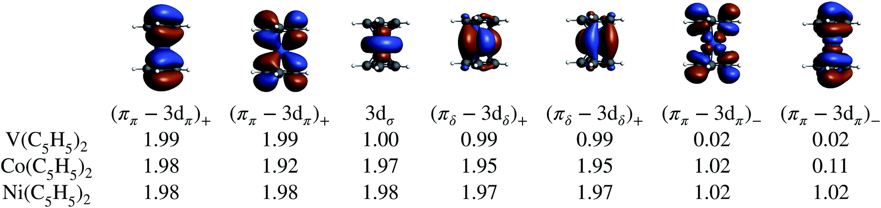
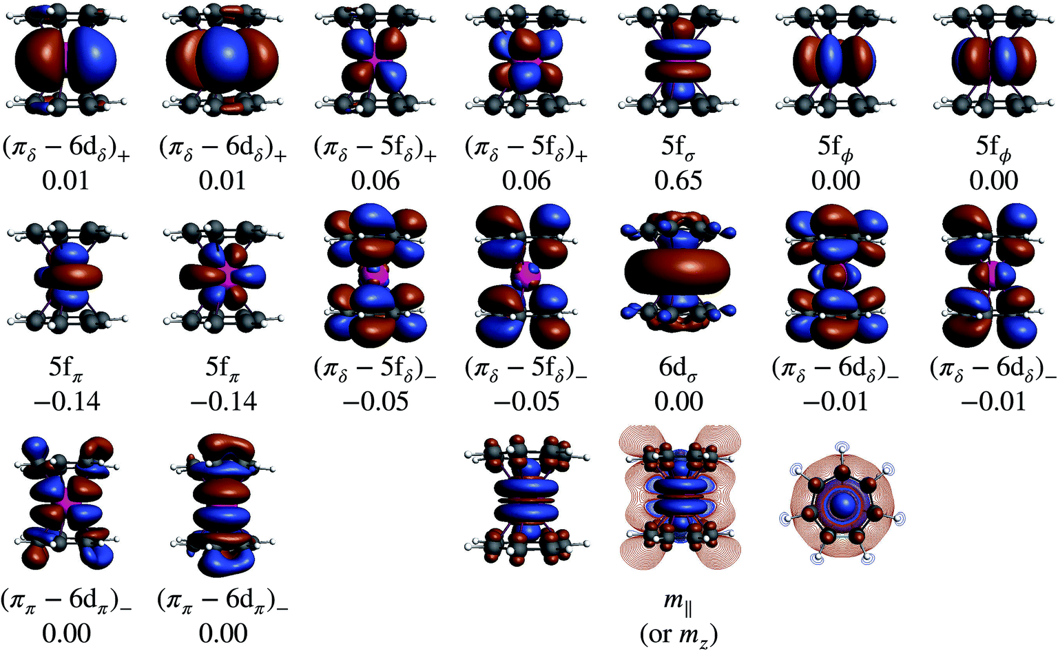
In the LF molecular orbital (MO) picture, the metal orbitals may form in-phase bonding and out-of-phase antibonding linear combinations with ligand orbitals of matching symmetry, which facilitates the important L–M donation bonding and M–L back-donation. Frontier MO diagrams for the eclipsed TM metallocenes and U(C7H7)2− are shown in Fig. 2, along with isosurfaces of relevant calculated orbitals.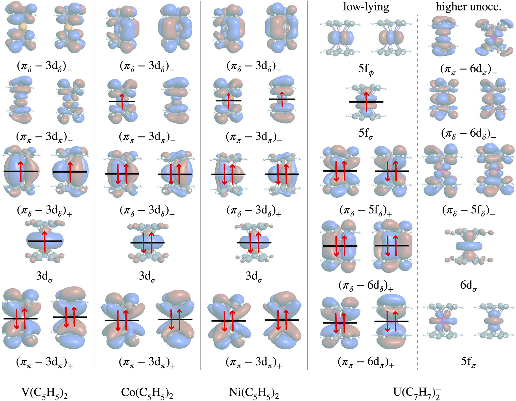 | ||
| Fig. 2 Frontier MO diagrams for the eclipsed TM metallocenes and U(C7H7)2−, and orbital compositions. The + and − subscripts denote the in-phase bonding and out-of-phase antibonding character. In each column, the energetic ordering is from bottom to top. For cobaltocene, the D5h → C2V symmetry reduction lifts the orbital degeneracies without changing the relative ordering of σ, π, and δ, and therefore the diagram is drawn for D5h. The orbitals were obtained from AOC BP/TZ2P DFT calculations in a spin-restricted open-shell fasion and are visualized as isosurfaces (±0.02 a.u.). | ||
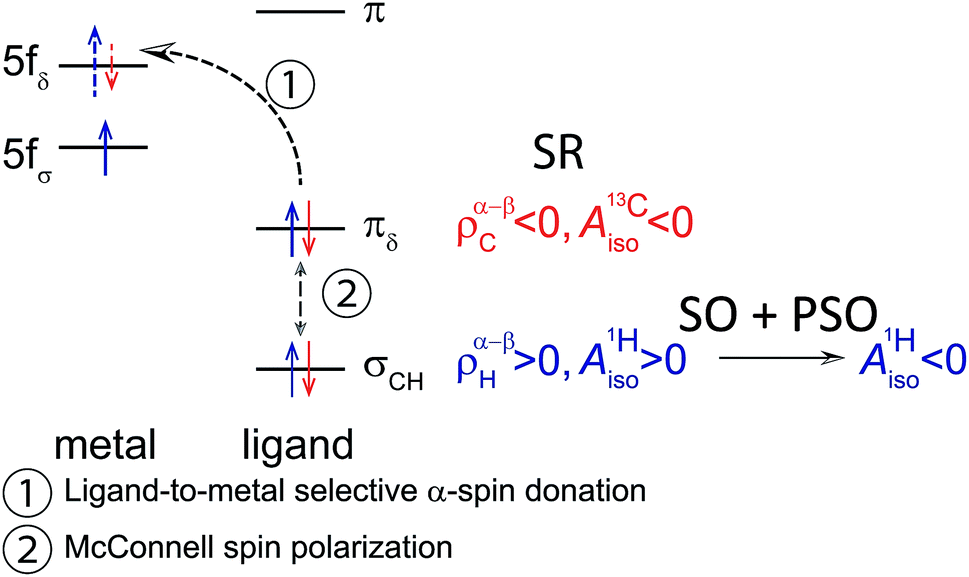
In the investigated TM metallocenes, most of the spin density is localized on the metal centers, as expected (Tables S3 and S4† and Fig. 3). Spin density in the ligands is caused by spin-delocalization, due to spin-selective L–M donation and/or spin-selective M–L back-donation, and ‘fine-tuned’ by spin polarization effects,42,97,98 as shown in Fig. 4. For example, a previous study showed that for nickelocene a positive spin density, i.e. an excess of α spin, around the carbons and at the carbon nuclei, as quantified experimentally by paramagnetic effects on the NMR shifts, is caused to ca. 85% by β spin L–M donation and to 15% by M–L α spin delocalization.42 Spin polarization then generates negative spin density at the ligand protons, i.e. opposite in sign to the carbon spin density. Because the ligand spin density is rooted in covalent effects, it can be sensitive to the choice of the functional in DFT calculations (‘delocalization error’).51,99 For the following semi-quantitative discussion of the spin densities, the calculations with the BP functional are deemed to be sufficiently accurate.28,49,50 It is important to distinguish in the discussion between orbitals of different spin, such that, for instance, 3dα refers collectively to the α spin TM 3d orbitals.
 | ||
| Fig. 3 Spin density distributions (BP/TZ2P, ±0.001 isosurfaces), for the eclipsed TM = V, Co metallocenes and U(C7H7)2− (experimental geometry for the 5f1σ GS and optimized geometry for the (πδ–5fδ)1− excited state (ES)), visualized perpendicular (left sub-panels) and parallel to the principal symmetry axis (right). Contour-line plots show the spin polarization in the vertical plane, containing the principal rotational axis, and in the horizontal plane defined by the C atoms of an arene ligand. The spin density plot for nickelocene is very similar to the one of cobaltocene and therefore not shown. Color code: orange (light shading) and blue (dark shading) stand for negative and positive spin density respectively. | ||
 | ||
| Fig. 4 Simplified schemes showing how a spin density in the TM metallocenes and U(C7H7)2− may arise at the arene C and H centers due to metal–ligand donation bonding and spin polarization effects. Each individual scheme shows the metal orbitals on the left side and the ligand orbitals of appropriate symmetry on the right side. L–M (top) and M–L (bottom) donation is evidenced with a blue arrow if it is selective for the α spin, and a red arrow if it is selective for the β spin. Double headed vertical arrows indicate spin polarization mechanisms. | ||
Mulliken and natural population analyses (MPA, NPA) were carried out to determine the atomic spin populations, i.e. measures of the integrated spin density per atom. The carbon spin populations in cobaltocene and nickelocene are positive, while the hydrogen spin populations are negative (Tables S3 and S4†). Both for Co(C5H5)2 and Ni(C5H5)2, L–M donation occurs into the metal 3dπ orbitals. Nickelocene has a filled 3dαπ shell, and therefore only β spin L–M donation can take place as shown in Fig. 4 (see Table S6† for numerical values). In Co(C5H5)2, the ligand may donate both spins, but it is clear from the calculations that β over α spin L–M donation is strongly favored (0.95 vs. 0.58 electrons respectively, Table S5†). Considering the JT structure, this is easily explained by the JT energy splitting of the 3dπ shell which renders the β spin donation into the empty lower-energy 3dβπ orbital (the corresponding 3dαπ is filled) favorable over the donation of either spin into the higher-energy 3dπ spin orbitals. However, the calculations showed that even in the D5h structure with degenerate 3dπ orbitals, β spin donation is favored. That is, L–M donation bonding is strongly β spin preferential both in nickelocene and cobaltocene.
The preferential β-spin L–M donation leaves the arene ππ framework with excess α-spin density, which is the source of the positive spin-density at the C centers in cobaltocene and nickelocene. A McConnell spin polarization mechanism34 of the C–H bonds then causes negative spin-density at the protons. These findings are in agreement with old derivations,36,37,93,96 more recent calculations,42,50,51 and experimental NMR data.36,100–103
M–L back-donation bonding involves predominantly the filled 3dδ metal orbitals. This donation is about twice as pronounced in cobaltocene than in nickelocene (∼0.30 vs. 0.15 electrons, see the sums of the 3dαδ and 3dβδ populations in Tables S5 and S6†) but only weakly spin-preferential. Hence, no significant excess spin density arises in the arene πδ networks from 3dδ M–L back-donation for the two complexes. The Co and Ni 3dσ populations are close to 2 (α and β combined, Tables S5 and S6†), due to their nonbonding character, and therefore also no significant source of ligand spin density. Note that the electron-spin flow due to bonding/back-bonding is essentially the same for the five-fold symmetric and the JT distorted cobaltocene structures.
The ligand spin density pattern in vanadocene is opposite to the Co and Ni counterparts, i.e. negative at C and positive at H. In 1960, Levy and Orgel38 proposed a CF mechanism as follows: the non-bonding 3dσ and 3dδ metal orbitals with single α-spin occupations render a ligand ππ electron transfer into the 3dπ orbitals energetically more favorable if the transferred electron also has α spin, such as to maximize the number of parallel spins at the metal. This would lead to an excess of β-spin density at the carbons, and by further spin-polarization within the ligand σ system would create α-spin density at the protons. This hypothesis was called into question in follow-up studies by Prins37 and Rettig and Drago36 in 1969. In fact, however, according to Fig. 2 there is a LF MO based mechanism that captures the essence of the Levy–Orgel model: the singly occupied 3dσ and 3dδ metal orbitals are able to spin-polarize the bonding (ππ–3dπ)+ orbitals that result from the L–M donation bonding, such that the α-spin component (ππ–3dπ)α+ is more strongly metal-centered whereas the β-spin component (ππ–3dπ)β+ is more ligand-centered. This would lead to the expected outcome as far as the C and H spin densities are concerned.
The vanadocene ligand atomic spin populations listed in Table S4† are small, because the core- vs. valence-shell spin polarization in the ligands, L–M donation bonding, and M–L back-bonding, cause competing effects. Irrespective of the functional used in the DFT calculations, the Mulliken C and H spin populations have the expected sign (C negative, H positive; see also the plot of the spin density distribution in vanadocene shown in Fig. 3), but the natural spin populations show variations. L–M donation occurs preferentially into the V 3dαπ orbitals, due to favorable exchange interactions (aligned spins), and less into 3dβπ orbitals (Table S6† and Fig. 4), leaving excess β spin in the arene ππ networks. This is in essence the Levy–Orgel mechanism, which causes negative C valence spin densities independently from the interaction of the ligand with the V 3dασ orbital. Weak α-spin M–L back-donation from the V 3dδ orbitals has the opposite effect on the carbons. The overall carbon spin populations are therefore small and sensitive to the functional used for the calculation. Some covalent interactions of the 3dσ spin orbitals with the arene ligands are evident from Table S6,† but they are weaker than the aforementioned L–M donation and M–L back-donation interactions. The source of the negative and positive spin densities around the C and H atoms, respectively, is rooted in a competing combination of the Levy–Orgel mechanism with subsequent C–H spin polarization, and M–L back-donation of α-spin density.
A recent analysis42 has shown the singly occupied V 3dασ orbital to be the main source of β-spin density at the arene carbon nuclei. Due to V being near the beginning of the 3d series, this orbital is radially very extended and overlaps with the C 1s orbitals such that α-spin-selective Pauli repulsion triggers an excess of C 1s β-spin density. Plots of the V 3dασ, Co 3dασ and Ni 3dασ natural localized MOs in Fig. 5 clearly show the large radial extension for vanadium. The signs of the ligand spin densities at the atomic nuclei are in line with the observed NMR shifts39,100,103 and reproduced in NMR calculations.42,50,52 The arene π orbital contributions to the carbon HyFCCs were quite small. This means that the LF analog of the Levy–Orgel mechanism is affecting the carbon valence shells but it does apparently not produce a strong C 1s core spin polarization in itself.
 | ||
| Fig. 5 Metal 3dασ/5fασ natural localized molecular orbital (isosurface value of ±0.02), and its composition, of the different TM metallocenes and U(C7H7)2−. BP/TZ2P calculations. Note the radial contraction of 3dσ from V to Co and Ni. | ||
To summarize the interactions in the TM systems: for Co and Ni, the main source of ligand spin density is L–M β-spin donation into the partially filled 3dπ metal orbitals, leaving excess α spin at the carbons and – via spin polarization – excess β spin at the protons. The M–L back donation is not strongly spin selective and weakly reinforces the spin effects from the L–M donation. For V, there is L–M α-spin donation into the empty 3dπ metal orbitals, leaving excess β spin at the carbons which causes excess α spin at the protons. The M–L back donation from the 3dδ orbitals in vanadocene is also α spin selective and counter-balances the spin effects of the L–M donation to some extent.
In order to rationalize the negative sign of  deduced from the magnetic resonance experiments, Gourier et al.27 proposed a scheme for the spin density distribution in U(C7H7)2− according to which the C and H centers have positive and negative spin densities. The scheme (see Fig. S3†) described a L–M selective β-spin donation mechanism into the singly occupied MO of essentially mixed 5fσ (38.5%) and 5fπ (51.4%) character (dictated by the combined effects of LF and SOC), assuming that the 5fσ and 5fπ orbitals are both covalently bonded. Since the spin density flow according to this scheme is similar to Co(C5H5)2, as far as the ligands are concerned, a similar covalent metal–ligand bonding was assumed to be present in the two sandwich complexes.
This conclusion does not hold true according to the present SR-DFT calculations, which consistently predict negative/positive spin densities at the C/H centers (Fig. 3, numerical data in Table S3†). The differences to the mechanism predicted by Gourier et al. are related to the non-bonding character of the 5fσ orbital which does not promote β-spin donation from the arene πσ MOs. This is also reflected in Table S5† which shows only a very small occupation of 0.04 of the 5fβσ orbital. Likewise, L–M electron donation into the 5fπ orbitals occurs to only a slight extent, given that the 5fπ orbitals are also essentially nonbonding, and this donation is not spin selective. Moreover, a similar ligand spin density has been obtained from SR-DFT test calculations using the experimental distorted geometry for U(C7H7)2− (not shown).
A comparable bonding scenario between U(C7H7)2− and Co(C5H5)2 as proposed by Gourier et al. (Fig. S3†), would be present if the unpaired electron in U(C7H7)2− would localize in the (πδ–5fδ)− MOs. I.e. in a CF picture, the UV+ ion would have the unpaired electron in the 5fδ shell. This scenario would indeed be cobaltocene-like: the partially filled U 5fδ shell would receive preferential β-spin donation from the occupied arene πδ frontier orbitals, leaving excess α spin at the carbons and spin-polarized proton environments with an excess of β spin.
To confirm this hypothesis, a (πδ–5fδ)1− excited state configuration for U(C7H7)2− was optimized at the BP/TZ2P level. The obtained geometry was nearly identical to the (5fσ)1 GS, but 1.88 eV (181 kJ mol−1) higher in energy, and the obtained Mulliken (natural) atomic spin populations for the U, C and H centers were 0.663 (0.648), 0.025 (0.026) and −0.001 (−0.001) respectively, i.e. close to those obtained for cobaltocene (Table S3†). The striking similarity with the GS of Co(C5H5)2 is also clearly seen in the spin density plots in Fig. 3. What renders the bonding scenarios similar now, between the 3d metallocene and the actinocene, is that in each case the highest occupied arene orbitals interact strongly with a partially filled metal valence shell of the same symmetry with respect to the rotational axis, leading to similar donation bonding and – importantly – to very similar spin preferences in this donation bonding. The fact that the donating orbitals are of δ symmetry with respect to the symmetry axis in the actinide case, but of π symmetry in cobaltocene, is secondary. However, this similar bonding and spin-density distribution in the 5f1 U(C7H7)2− and d7 cobaltocene occurs only if one considers an excited state of the former system that is not populated at room temperature or below.
There are potentially two vanadocene-like mechanisms according to which spin density could be distributed in U(C7H7)2− GS as a consequence of metal–ligand bonding: a L–M spin-selective donation mechanism (as shown in Fig. 4) and a direct spin-polarization of the ligand σ orbitals. A spin polarization mechanism mediated by the U 6s and 6p orbitals was speculated to operate in the 5f2 uranocene complex, U(C8H8), driving the ligand 1H and 13C contact shifts.104,105 However, as detailed in Section S5,† we found no evidence of a mechanism involving U 6s/p, or a direct polarization as in vanadocene, and overall qualitatively similar spin density distributions and L–M donation mechanisms in the two actinocenes. We leave a discussion of the U(C8H8) NMR shifts for a separate study.
Considering a vanadocene-like L–M spin-selective donation bonding (as shown in Fig. 4), this scenario is supported by the fact that the relevant orbitals participate strongly in covalent bonding (Fig. 2). As in vanadocene, selective α-spin donation, favored by exchange interactions in an Orgel–Levy type fashion, occurs into the U 5fαδ spin-orbitals, leaving excess β-spin density in the arene πδ networks which cause the calculated negative C spin populations and ultimately positive H spin populations (Table S3†).
The effect of SOC on the spin density distribution in U(C7H7)2− will complicate the effects further. As shown in the following section, SOC mixes the (5fσ)1 (∼70%) and the (5fπ)1 (∼30%) configurations in the GS of U(C7H7)2−. The mixing is such that 5fβπ spin-orbitals are populated at the expense of the 5fασ spin-orbitals, because the SOC mixes opposite spin projections. A L–M donation bonding into the 5fδ empty orbitals in a (5fβπ)1 configuration of the metal would follow a vanadocene-like Orgel–Levy mechanism, too, in the sense that it would be spin-selective such as to maximize the parallel spins at the metal. This aspect is evident from the spin density visualized in Fig. 6 for an excited (5fβπ)1 configuration of U(C7H7)2−. The L–M donation is β spin selective and leaves excess α spin density at the carbons. A competing α- vs. β-spin L–M donation triggered by the SOC must therefore be expected. However, given that the (5fπ)1 configuration has only a minor contribution to the SOC GS of U(C7H7)2−, SOC does not change the signs of the ligand atomic spin populations relative to the SR calculations, it only reduces their magnitudes.
 | ||
| Fig. 6 Spin density distributions (isosurfaces, ±0.001) for the (5fβπ)1 excited electronic state of U(C7H7)2−. Contour-line plots show the spin polarization in the vertical plane, containing the seven-fold rotational axis, and in the horizontal plane defined by the C atoms of an arene ligand. AOC BP/TZ2P calculations with optimized structure. Color code: orange (light shading) and blue (dark shading) stand for negative and positive spin density, respectively. | ||
We conclude that a similar metal–ligand bonding takes place in the 5f1 U(C7H7)2− and the 3d3 vanadocene. The L–M selective α-spin donation, common to both systems, can be viewed as resulting from interactions by which the number of unpaired spins in formally non-bonding orbitals at the metal is maximized. Since we are concerned with exact or near spatial degeneracies, however, and since the SOC may take a strong influence on the electronic structure of the 5f1 U(C7H7)2−, it is important to corroborate the DFT analysis with the help of multi-configurational wavefunction calculations, and with explicit calculations of the magnetic properties. The application of multiconfigurational wavefunction methods to study energetics and bonding scenarios in metallocenes, lanthanocenes and actinocenes has proved to be very valuable previously.106–111
3.3 Electronic structure and metal–ligand bonding from wave-function approaches
 | ||
| Fig. 7 Selected GS NOs and their occupations obtained from CAS-SR calculations on the eclipsed BP/TZ2P geometries of the TM metallocenes. The converged NOs for cobaltocene are shown as isosurfaces (±0.02) and representative of the series. | ||
The various CAS calculations predict an essentially single-configurational GS for each metallocene, as the orbital degeneracy of cobaltocene is split by ∼0.42 eV upon the JT distortion (which is roughly the same as the corresponding orbital energy splitting for the α-spin orbitals in the BP DFT calculation). The NOs and their occupations are in qualitative agreement with the DFT calculations, showing that the unpaired electron(s) are localized in the (ππ–3dπ)− MOs in cobaltocene and nickelocene, and in the 3dσ and (πδ–3dδ)+ MOs in vanadocene. Electron correlation involving the (ππ–3dπ)+ and (ππ–3dπ)− MO pairs causes some modest multi-reference character with partial (ππ–3dπ)− occupations, which appears to be the strongest in the GS of cobaltocene, and this correlation is required to obtain the correct ground spin state for this system (see Section S3†). The DFT analysis already revealed that these two pairs of MOs are vital to capture the majority of spin delocalization due to L–M donation bonding in either of the metallocenes. This spin-preferred donation is further confirmed by the CAS-SR GS atomic spin-populations (MPA) collected in Table 1 for Co(C5H5)2 and V(C5H5)2. However, the signs of the H spin populations in cobaltocene, and of C in vanadocene are not reproduced by CAS-SR calculations with attainable active spaces, because they are dominated by spin polarization of the arene σ networks. An even qualitative description of these effects requires much larger active spaces, for which an orbital optimization becomes impractical. The signs for the C and H atomic spin-populations in cobaltocene and vanadocene in Table 1 agree qualitatively with those from the DFT calculations when a much larger orbital active space is used in a ‘RASCI’ approach (see details in Section S2†).
| System/approach | Metal center | C | H |
|---|---|---|---|
| a The eclipsed BP/TZ2P geometries are used for the TM metallocenes and the eclipsed experimental geometry is used for the actiocene. b Italic type is used to indicate that the dimension of the configuration interaction space is too small to create qualitatively correct spin populations. c See Section S2 for details on the chosen RAS subspaces. | |||
| Co(C5H5)2 | Co | C | H |
| CAS(11, 12)-SR | 0.830 | 0.015 | 0.002 |
| RASCIc | 0.820 | 0.020 | −0.002 |
| V(C5H5)2 | V | C | H |
| CAS(7, 7)-SR | 2.960 | 0.003 | 0.001 |
| RASCIc | 3.030 | −0.004 | 0.001 |
| U(C7H7)2− | U | C | H |
| CAS(9, 13)-SR | 1.218 | −0.015 | −0.001 |
| RASCIc | 1.216 | −0.014 | −0.001 |
| State | Compositionb | ΔE (eV) | Compositionc | ΔE (eV) |
|---|---|---|---|---|
| a The eclipsed experimental geometry is used. b The compositions of the SR wave functions are given in terms of the NOs that are significantly populated; the 6d+δ, 5f+δ and 5f−δ notations are used for brevity instead of (πδ–6dδ)+, (πδ–5fδ)+ and (πδ–5fδ)− (see Fig. 8). c Given in terms of the SR states on the first column. | ||||
| CAS(9, 13)-SR | CAS(9, 13)-SO | |||
| 2Σ | (6d+δ)3.95(5f+δ)3.74(5fσ)0.99(5f−δ)0.24 | 0.00 (0.00) | 70%2Σ + 30%2Π | 0.00 (0.00) |
| 2Φ | (6d+δ)3.94(5f+δ)3.74(5fϕ)0.99(5f−δ)0.25 | 0.29 (0.40) | 98%2Φ + 2%2Δ | 0.17 (0.28) |
| 2Π | (6d+δ)3.95(5f+δ)3.72(5fπ)0.99(5f−δ)0.23 | 0.50 (0.47) | 92%2Π + 8%2Δ | 0.82 (0.80) |
| 2Δ | (6d+δ)3.94(5f+δ)3.56(5f−δ)0.97(5fϕ)0.23(5fπ)0.15 | 1.91 (1.83) | 70%2Π + 30%2Σ | 0.93 (0.92) |
| 100%2Φ | 0.94 (1.06) | |||
| 92%2Δ + 8%2Π | 2.13 (2.07) | |||
| 98%2Δ + 2%2Φ | 2.39 (2.32) | |||
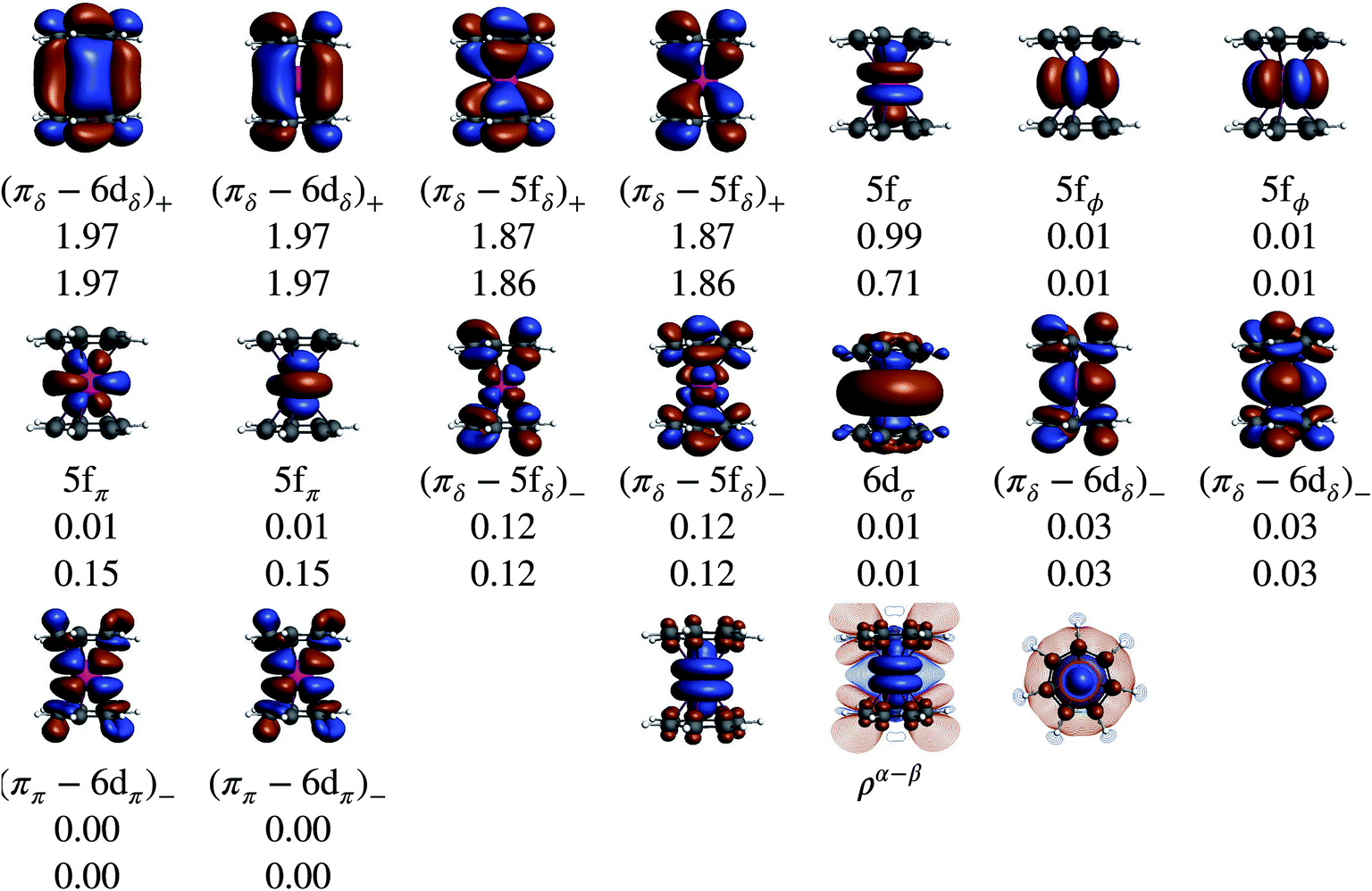 | ||
| Fig. 8 NOs (isosurface value of ±0.02) and their occupations for the U(C7H7)2− GS, obtained through CAS(9, 13) calculations on the eclipsed experimental structure. SR and SOC occupations are listed on the first and second line respectively. The GS CAS(9, 13)-SR spin density (ρα–β) is also visualized with an isosurface of ±0.001. Color code for ρα–β: orange (light shading) and blue (dark shading) stand for negative and positive spin density, respectively. | ||
Without SOC, the GS is 2Σ and the wavefunction is mostly single-configurational. The dominant configuration is (5fσ)1 with about 80% weight. The next most important weight corresponds to excited configurations in which electrons are promoted from (πδ–5fδ)+ to (πδ–5fδ)− MOs, as indicated by the GS NO occupations listed in Table 2 and Fig. 8. Above 2Σ appear two orbitally doubly degenerate states, first 2Φ and then 2Π. Similar to the GS, these states are dominated by the expected (5fϕ)1 and (5fπ)1 configurations, and the wavefunctions have contributions from configurations that correspond to (πδ–5fδ)+ to (πδ–5fδ)− excitations. That is, these low-energy states are mainly assigned to single-electron LF transitions among the U 5fσ, 5fπ, and 5fϕ orbitals, while the electron correlation mixes (πδ–5fδ)+ to (πδ–5fδ)− excited configurations into the respective wavefunctions. At a much higher energy, ∼1.9 eV with CAS-SR and ∼1.8 eV with PT2-SR, occurs the 2Δ state where the unpaired electron populates the antibonding (πδ–5fδ)− MOs, in agreement with DFT/BP results (see the previous section and ref. 28).
The electronic structure of U(C7H7)2− is dictated by a delicate interplay between SOC and LF effects. If one considers a free UV ion, the SOC splits (Table S9†) the 2F SR ground term into the sixfold degenerate 2F5/2 and eightfold degenerate 2F7/2 SOC levels, characterized by a total angular momentum J = 5/2 and 7/2, and the projections MJ = J, …, −J. In the complex, (i) each J manifold splits into Kramers doublets, and (ii) due to the high symmetry, MJ remains a good quantum number such that states of different J but same MJ mix. For example, 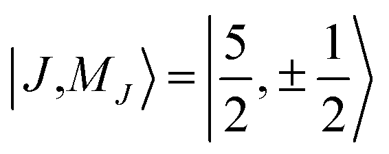 and
and  free ion spinors may mix, which serves to adjust the relative admixture of the SR 2Σ and 2Π components of opposite spin in the SOC GS. The SOC can also mix 2Π with 2Δ, and 2Δ with 2Φ. Since the 2Δ state is high in energy, its SOC mixing with the other states is insignificant (Table 2), which also causes the 2Φ states to undergo only weak SOC. Pronounced SOC mixing occurs between the closely spaced 2Σ and 2Π states.
The SOC GS is clearly of 2Σ parentage (70%) but exhibits a sizable 2Π weight (30%) as shown in Table 2. The 2Σ–2Π SOC mixing is also evident through the comparison of the natural occupations listed in Fig. 8, which shows that under the effect of SOC, ∼0.3 electrons are depleted from the 5fσ orbital and redistributed among the 5fπ orbitals. The CAS(9, 13)-SR(SO) and PT2(9, 13)-SR(SO) potential surface scans (Fig. S2†) along the metal-ring distances show, however, that the structures obtained with or without the treatment of SOC are identical, due to the predominantly non-bonding nature of the 5fσ and 5fπ orbitals. This is also the reason why the SR-DFT structure optimizations are reliable. The obtained PT2-SO and the experimental metal-aryl distances (1.98 Å) are identical, proving the adequacy of the active space in capturing the bonding interactions in this actinocene.
It is worth noting that Gourier et al.27 assigned a dominant 5f1π character, instead of 5f1σ, for the GS of U(C7H7)2−, based on a CF analysis of the g factors. Gourier et al. established that the  Kramers pair dominates the SOC GS. The electron density weight for these spinors is 57.1% 5fπ and 42.9% 5fσ.114 To achieve agreement of the calculated and the measured g factors, however, a mixing of the
  with
with  spinors was proposed (in proportions of about 90% and 10%), which would only be allowed if the high symmetry of the complex were removed. The composition of the
  spinors is 5fδ (14.2%) and 5fϕ (85.8%),27,114 such that the mixing would introduce 5fδ and 5fϕ character in the GS. The final SOC GS composition was concluded to be 5fπ (51.4%), 5fσ (38.5%), 5fϕ (8.9%) and 5fδ (1.5%). A derivation is presented in Section S4.† The difference with the GS composition predicted by the ab initio calculations arises from the fact that in the LF picture the 5fπ metal orbitals are destabilized relative to 5fσ, which reduces the π contributions in the GS relative to the
  free-ion spinors. This mechanism involves free-ion states of different J but same MJ that are allowed to mix under the linear symmetry of the complex, but not in the free metal ion.
Table 1 lists GS atomic spin populations obtained from CAS(9, 13)-SR and RASCI approaches. An isosurface plot of the CAS(9, 13)-SR spin density is shown in Fig. 8. In agreement with DFT (Table S3†), the wavefunction calculations predict negative spin populations at the carbons, and an excess of α spin density at uranium beyond the formal single occupation. As already stated in the DFT analysis, positive spin populations at the H centers are then caused by the McConnell polarization mechanism, which acts via the ligand σ networks. Attempts to capture this polarization via RASCI calculations were unsuccessful due to technical limitations regarding the size of the active space. Nonetheless, the wavefunction calculations show clearly that, in the GS of U(C7H7)2−, an electron flow within the π system, facilitated in particular by the metal–ligand bonding (πδ–5fδ)+ MOs, creates negative spin density at the ligand C centers, in agreement with the DFT calculations. Agreement was further noted for the spin populations of the U and C atoms in the 2Π and 2Δ excited states. For instance, in the 2Δ excited state, values of 0.675 and 0.021, respectively, were obtained, which are similar to those obtained from BP/TZ2P. Therefore, the ab initio wavefunction calculations confirm that a cobaltocene-like spin density distribution in U(C7H7)2−, i.e. with excess α spin density at the carbons due to L–M β-spin donation into a partially filled metal shell, occurs only in a high-energy excited state.
In order to visualize the effect of SOC on the spin magnetization (‘spin density’) in U(C7H7)2−, isosurfaces of the GS natural spin-orbitals (NSOs)108,114,115 and spin magnetizations are shown in Fig. 9. CAS-SO spin and angular momentum expectation values, 〈S〉 and 〈L〉, are listed in Table S13.† The ∥ direction is along the principal axis of symmetry, coinciding with the z direction. Without SOC and with the usual choice of z for the spin quantization axis, the spin magnetization corresponds to the usual spin density, and 〈S∥〉 would be equal to MS. The 〈S∥〉 and 〈L∥〉 are around ±0.197 and ±0.298, i.e. very different from the 〈S∥〉 = ±0.5 for a SR spin-doublet GS and 〈L∥〉 = 0 for an unpaired electron in the 5fσ orbital. The NSO data reaffirm that the difference in the SOC and SR 〈S∥〉 and 〈L∥〉 values is caused predominantly by the SOC mixing of the 5fσ and 5fπ orbitals, and, to a lesser extent, by the 5fδ admixture in the SR wavefunction (Fig. 9). The ∥ spin magnetization (m∥) is concentrated in a prolate shape around the actinide center, clearly showing its origin from the spins at the uranium center. The spin magnetization plots also show important contributions from the ligand π network, facilitated by the covalent πδ–5fδ interactions. Indeed, the 5fδ and 6dδ bonding NSOs bring positive contributions to the metal-based spin magnetization, meanwhile the corresponding antibonding NSOs bring negative contributions to the largely ligand-based spin magnetization which is ultimately seen in either plot of m∥. The behavior appears similar to the LF Levy–Orgel mechanism for the spin density distribution in vanadocene.
 | ||
| Fig. 9 NSOs and spin populations for a magnetic field along the ∥ direction (along the principal symmetry axis), for the U(C7H7)2− GS component with 〈SZ〉 > 0, from CAS(9, 13)-SO calculations. The spin-magnetization component m∥ is also shown. The spin populations add up to 2 〈S∥〉. Isosurface values: ±0.02 (NSOs), ±0.001 (spin magnetization). For m∥, the polarized magnetization in the vertical plane containing the seven-fold rotational axis and in the horizontal plane defined by the C atoms of an arene ligand, are also shown. Color code for m∥: orange (light shading) and blue (dark shading) correspond to negative and positive contributions. | ||
3.4 Magnetic properties
| Approach | Co(C5H5)2 | U(C7H7)2− | ||||
|---|---|---|---|---|---|---|
| g 1 | g 2 | g 3 | g ∥ | g ⊥ | ||
| a The JT geometry is used for cobaltocene and the eclipsed experimental geometry is used for U(C7H7)2−. b Perturbative treatment of SOC. c The CAS(11, 12) is used for cobaltocene and the CAS(9, 13), for U(C7H7)2−. d Data from ref. 41 for cobaltocene and from ref. 27 for U(C7H7)2−. | ||||||
| BP | SR-ZORAb | 1.84 | 2.01 | 2.05 | 2.00 | 0.43 |
| SO-ZORA | 1.84 | 2.01 | 2.05 | 1.42 | 1.15 | |
| PBE | SR-ZORAb | 1.83 | 2.01 | 2.05 | 2.00 | 0.42 |
| SO-ZORA | 1.83 | 2.00 | 2.05 | 1.43 | 1.10 | |
| B3LYP | SO-ZORA | 1.47 | 1.52 | 2.47 | 1.37 | 1.28 |
| PBE0 | SO-ZORA | 1.51 | 1.51 | 2.46 | 1.34 | 1.34 |
| CAS-SOc | 1.78 | 2.04 | 2.16 | 1.38 | 2.27 | |
| PT2-SOc | 1.77 | 2.03 | 2.16 | 1.36 | 2.33 | |
| Expt.d | 1.73 | 1.89 | 1.96 | 1.24 | 2.37 | |
For U(C7H7)2−, the only experimental data available are from the EPR study of Gourier et al.27 who reported an axial g tensor with ±g∥ = 1.24 and ±g⊥ = 2.37. The g factors predicted by CAS(PT2)-SO calculations are in good agreement with the measurements (Table 3). A comparison between the g factors obtained with the different active spaces (see Table S15†) reveals the origins of the g∥ and g⊥ components. g∥ is predicted roughly similar by all of the active spaces and therefore it is due to the SOC of the 5fσ and 5fπ orbitals in the presence of the ligands, creating an orbital magnetic moment. On the other hand, the magnitude of g⊥ is driven by the metal–ligand bonding and dictated by the 5fδ admixture into the GS. The differences from |g∥| = 0.86 and |g⊥ = 2.57| for idealized  spinors shows how the measured and calculated ab initio g-factors indicate the deviations of the GS wavefunction from the free-ion Kramers pair. It is important to reiterate that the observed |g∥| = 1.24 is closely tied to a much larger contribution of 5fσ in the GS than it is present in the free ion spinors. This also implies that, in the GS of U(C7H7)2−, there is actually a LF admixture of the
  and
and  free ion spinors.
The g factors predicted by relativistic DFT calculations expose some difficulties to capture the delicate balance between LF and SOC in the U(C7H7)2− GS with this single-configuration approach. The SR-ZORA calculations with a pure functional, treating SOC as a linear perturbation, give g∥ close to ge and a nearly vanishing g⊥. This is due to the failure of perturbation theory to recover the strong effect of SOC on g∥, and due to the inability to account for the multiconfigurational GS, which affects g⊥. It is worth noting that the SR-ZORA approach yields correct g factors for the TM metallocenes since these systems are neither governed by strong SOC nor do they have multiconfigurational GSs. When SOC is introduced self-consistently in the SO-ZORA DFT calculations, and notably when a hybrid functional is used, the U(C7H7)2−g∥ greatly improves but g⊥ does not. That is, the strong SOC is accounted for correctly, but the multiconfigurational GS is still not described well. g factors for various excited states of U(C7H7)2− were calculated using the SO-ZORA/BP approach, and compared to PT2(9, 13)-SO (Table 4). The DFT and wavefunction calculations give comparable relative energies between the different states, and the excited state g factors agree very well, too. The excited states are orbitally degenerate, but otherwise they have less of a multiconfigurational character than the GS. Consequently, the state energies and g factors are well described by SO-ZORA DFT calculations where each degenerate pair of orbitals shares the electron occupation evenly.
| SO state | SO-ZORA/BP | PT2(9, 13)-SO | ||||
|---|---|---|---|---|---|---|
| ΔEb (eV) | g ∥ | g⊥ | ΔEb (eV) | g ∥ | g ⊥ | |
| a The eclipsed experimental geometry is used. b The SO-ZORA relative energies are obtained in ΔSCF calculations while the PT2-SO excitation energies are from Table 2. | ||||||
| 2Σ1/2 | 0.00 | 1.42 | 1.15 | 0.00 | 1.36 | 2.33 |
| 2Φ5/2 | 0.31 | 3.96 | 0.00 | 0.27 | 4.08 | 0.00 |
| 2Π3/2 | 0.75 | 3.67 | 0.00 | 0.80 | 3.78 | 0.02 |
| 2Δ5/2 | 2.35 | 5.93 | 0.00 | 2.32 | 5.70 | 0.01 |
 and
and  correspond to the average of the individual isotropic HyFCCs.
| Functional | Approach | Co(C5H5)2 | U(C7H7)2− | ||
|---|---|---|---|---|---|
|
|
|
|
|
||
| a GS data. The JT BP/TZ2P geometry is used for cobaltocene while the eclipsed experimental geometry is used for U(C7H7)2−. b Perturbative treatment of SOC. c The value in parenthesis were obtained from a spin-unrestricted collinear SO-ZORA calculation using TZP basis sets. d Data from ref. 41 for cobaltocene and from ref. 27 for U(C7H7)2−. | |||||
| BP | SR-ZORA | 4.95 | −2.97 | −0.59 | 5.10 |
| SR-ZORAb | 4.85 | −2.97 | −0.18 | 5.19 | |
| SO-ZORA | 4.81 | −2.97 | −0.64 (−1.55)c | −1.33 (−0.95)c | |
| PBE | SR-ZORA | 5.39 | −2.86 | −0.69 | 5.02 |
| SR-ZORAb | 5.28 | −2.86 | −0.28 | 5.12 | |
| SO-ZORA | 5.37 | −2.86 | −0.65 | −1.34 | |
| B3LYP | SR-ZORA | 5.56 | −1.85 | −1.12 | 4.99 |
| SO-ZORA | 5.43 | −1.86 | −0.61 | −1.15 | |
| PBE0 | SR-ZORA | 6.00 | −1.96 | −1.36 | 5.32 |
| SO-ZORA | 5.88 | −1.97 | −0.64 (−2.20)c | −1.15 (−1.48)c | |
| Expt.d | — | −2.4 | — | −2.7 | |


For the metallocenes, the calculated  and
and  vary among different functionals but are in qualitative agreement and in reasonable quantitative agreement with available measurements. As in the case of the g factors, the weak SOC is sufficiently accounted for by the SR-ZORA plus perturbative SOC approach. The signs of
  and
and  in the different metallocenes are in agreement with the signs of the calculated atomic spin populations and further validate the deduced mechanisms that cause the spin density distributions due to metal–ligand bonding. In particular, positive and negative
  and
and  are predicted for cobaltocene, in agreement with the positive and negative atomic spin populations that arise through the covalent metal–ligand bonding interactions.
DFT is expected to give reasonable ligand HyFCCs also for U(C7H7)2−, since they are not as sensitive to the mixing among the different non-bonding uranium orbitals as the g-tensor. At the SR level, irrespective of the used functional, the  and
and  are negative and positive, respectively, in agreement with the signs of the calculated C and H atomic spin populations. The sign of
  is in disagreement with that of cobaltocene, but also with the measurement. Rather, the calculated SR
  for U(C7H7)2− is in qualitative agreement with that of vanadocene.
The reader is reminded that the spin density distribution (and, to some degree, its mechanism), due to metal–ligand bonding, is similar for U(C7H7)2− and vanadocene, but not cobaltocene or nickelocene. The empty 5fδ orbitals of the U center and the partially filled 3dπ orbitals of the Co center, that are primarily involved in metal–ligand bonding, are responsible for opposite signs of the carbon spin densities within U(C7H7)2− and cobaltocene, and therefore ultimately also for the sign of the electron spin contributions to  .
.
Strikingly, however, when the strong SOC is introduced in the calculations, via the SO-ZORA approach, the predicted  for U(C7H7)2− changes sign and agrees in sign and order of magnitude with the one predicted for cobaltocene, and with the measured one. The 1.7 to 1.2 MHz deviations between the SO-ZORA DFT data and the experimental value may appear large at first, but we must emphasize that the SOC improves the calculated
  by more than 6 MHz toward the experiment and restores the correct sign. This finding strongly suggests that the observed negative sign for the proton HyFCC in U(C7H7)2− is governed by strong SOC and the orbital angular momentum that it creates. Consequently, the HyFCC is dominated by the PSO (paramagnetic interaction of the nuclear spin with the electron orbital angular momentum) mechanism, which happens to be opposite to the sign of the spin density at the protons. Note that PSO-type mechanisms were also found to be dominant for pNMR ligand shifts in several actinide systems.45 As hypothesized in the introduction, the metal–ligand covalent bonding in the ground states of U(C7H7)2− and cobaltocene is very different, as far as the spin density is concerned, while the same sign and order of magnitude for
  is caused by SOC in U(C7H7)2−.
4 Conclusions
The aim of this study was to investigate whether there is a similarity in the metal–ligand (M–L) bonding occuring in actinide and TM complexes. Metallocenes were chosen for this investigation, because a similarity of bonding between the 5f1 U(C7H7)2− and 3d7 cobaltocene sandwich complexes had been postulated previously, based on experimental magnetic resonance data and a theoretical analysis.27 The calculated spin density distributions within the two systems are very different, however, with or without a SOC treatment, and consistent between DFT and CAS wavefunction calculations. The differences were tracked-down to different 5f vs. 3d covalent bonding scenarios. On the other hand, the 5f1 U(C7H7)2− has similar M–L bonding characteristics as the 3d3 vanadocene.Unlike the electronic GSs of the metallocenes, which are well-defined single configurational and hardly influenced by SOC, the GS of U(C7H7)2− is multiconfigurational with important weights on the 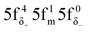 and
and 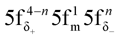 configurations (m = σ, π; n = 1, 2). The 5fπ and 5fδ occupations in the GS are due to strong SOC and ligand-to-metal donation bonding, respectively, and they refine the magnitudes of the g∥ and g⊥ components of the axial g tensor. DFT, with an appropriate treatment of relativistic effects, can provide accurately the g∥ component, but a multiconfigurational spin–orbit coupled wave function approach is needed to recover an accurate g⊥ component as well. The TM metallocene g values are predicted accurately with both DFT and ab initio wavefunction approaches.
In cobaltocene and nickelocene, the metal center is involved in strong covalent bonding with filled arene ππ MOs, resulting in selective β-spin density ligand-to-metal donation into the partly filled 3dπ metal orbitals. This process leaves excess α spin density at the arene C atoms. A McConnell spin polarization mechanism then causes negative spin density at the arene H atoms. Therefore, negative 1H isotropic HyFCC is predicted, in agreement with measurements.36,41
This spin density distribution mechanism is not present in the 5f1 U(C7H7)2−, mainly because the bonding here involves ligand πδ MOs and empty 5fδ orbitals. A selective α-spin density ligand-to-metal donation then leaves negative spin density at the arene C atoms, and a McConnell spin-polarization mechanisms creates positive spin density at the arene H atoms. This mechanism is very similar to how ligand spin density in vanadocene would arise by considering selective α-spin donation from filled ligand ππ orbitals into the empty V 3dπ orbitals.
The electron spin contribution to the U(C7H7)2− 1H isotropic HyFCC is opposite to that in cobaltocene, in agreement with the signs of the ligand atomic spin populations, and therefore confirms the established spin density distributions and underlying mechanisms. However, calculations that properly treat the strong SOC predict 1H isotropic HyFCCs that are consistent in sign and order of magnitude with those of cobaltocene, and that agree with the measured data.27 SOC does not qualitatively affect the ligand spin density in U(C7H7)2−. Instead, a large ‘PSO’ hyperfine coupling contribution arises from the orbital angular momentum created by the SOC.
The similar 1H isotropic HyFCC in the 5f1 U(C7H7)2− and the 3d7 cobaltocene is due to the strong SOC in the former, rather than similar metal–ligand bonding. Instead, the 5f1 U(C7H7)2− and the 3d3 vanadocene share similar bonding characteristics, in the sense that the highest occupied ligand π orbital has the same nodal structure as a pair of empty metal valence orbitals, causing donation bonding into these metal orbitals, donation which, due to unpaired spins in other non-bonding metal orbitals, is rendered selective for the α spin. A concluding scheme for U(C7H7)2− is shown in Fig. 10.
 | ||
| Fig. 10 Simplified scheme concluding the underlying mechanism for the spin density (ρ) (spin magnetization (m)) distribution in U(C7H7)2− which drives the signs of the arene 13C and 1H isotropic HyFCCs. | ||
Through the use of relativistic quantum chemical methods and bonding analysis tools, the present study offers insight into the similarities and differences of ligand to metal donation bonding, and the resulting spin density distributions in the ligands, for transition metals vs. actinides. For the systems studied herein, the analysis shows that experimental HyFCCs (and, by extension, paramagnetic NMR shifts) can be very powerful indicators of the donation bonding, but SOC can very much complicate the picture.
Conflicts of interest
There are no conflicts to declare.Acknowledgements
The authors acknowledge support from the U.S. Department of Energy, Office of Basic Energy Sciences, Heavy Element Chemistry program, under grant DE-SC0001136 (formerly DE-FG02-09ER16066). We thank the Center for Computational Research (CCR) at the University at Buffalo for providing computational resources.References
- A. Haaland, Acc. Chem. Res., 1979, 12, 415–422 CrossRef.
- B. E. Bursten and R. J. Strittmatter, Angew. Chem., Int. Ed. Engl., 1991, 30, 1069–1085 CrossRef.
- N. Fey, J. Chem. Technol. Biotechnol., 1999, 74, 852–862 CrossRef.
- H. Werner, Angew. Chem., Int. Ed., 2012, 51, 6052–6058 CrossRef PubMed.
- T. J. Kealy and P. L. Pauson, Nature, 1951, 168, 1039–1040 CrossRef.
- S. A. Miller, J. A. Tebboth and J. F. Tremaine, J. Chem. Soc., 1952, 632–635 RSC.
- G. Wilkinson, M. Rosenblum, M. C. Whiting and R. B. Woodward, J. Am. Chem. Soc., 1952, 74, 2125–2126 CrossRef.
- E. Fischer and W. Pfab, Z. Naturforsch., B: J. Chem. Sci., 1952, 7, 377–379 Search PubMed.
- A. Streitwieser Jr and U. Mueller-Westerhoff, J. Am. Chem. Soc., 1968, 90, 7364 CrossRef.
- A. Streitwieser Jr and N. Yoshida, J. Am. Chem. Soc., 1969, 91, 7528 CrossRef.
- J. Goffart, J. Fuger, D. Brown and G. Duyckaerts, Inorg. Nucl. Chem. Lett., 1974, 10, 413–419 CrossRef.
- D. G. Karraker, J. A. Stone, E. R. Jones Jr and N. Edelstein, J. Am. Chem. Soc., 1970, 92, 4841–4845 CrossRef.
- A. Avdeef, K. N. Raymond, K. O. Hodgson and A. Zalkin, Inorg. Chem., 1972, 11, 1083–1088 CrossRef.
- D. Seyferth, Organometallics, 2004, 23, 3562–3583 CrossRef.
- J.-C. Berthet, P. Thuéry, N. Garin, J.-P. Dognon, T. Cantat and M. Ephritikhine, J. Am. Chem. Soc., 2013, 135, 10003–10006 CrossRef PubMed.
- A. Kerridge, R. Coates and N. Kaltsoyannis, J. Phys. Chem. A, 2009, 113, 2896–2905 CrossRef PubMed.
- A. Kerridge, Dalton Trans., 2013, 42, 16428–16436 RSC.
- A. Streitwieser, S. A. Kinsley, J. T. Rigsbee, I. L. Fragala and E. Ciliberto, J. Am. Chem. Soc., 1985, 107, 7786–7788 CrossRef.
- K. N. Raymond and C. W. Eigenbrot, Acc. Chem. Res., 1980, 13, 276–283 CrossRef.
- M. Dolg, P. Fulde, H. Stoll, H. Preuss, A. Chang and R. M. Pitzer, Chem. Phys., 1995, 195, 71–82 CrossRef.
- M. Dolg and O. Mooßen, J. Organomet. Chem., 2015, 794, 17–22 CrossRef.
- I. Grenthe, J. Drożdżynński, T. Fujino, E. C. Buck, T. E. Albrecht-Schmitt and S. F. Wolf, in Uranium, ed. L. R. Morss, N. M. Edelstein and J. Fuger, Springer Netherlands, Dordrecht, 2006, pp. 253–698 Search PubMed.
- D. L. Clark, M. P. Neu, W. Runde and D. W. Keogh, in Uranium and Uranium Compounds, John Wiley & Sons, Inc., New York, 2000 Search PubMed.
- M. Pepper and B. E. Bursten, Chem. Rev., 1991, 91, 719–741 CrossRef.
- T. W. Hayton, Nat. Chem., 2013, 5, 451–452 CrossRef PubMed.
- T. Arliguie, M. Lance, M. Nierlich, J. Vigner and M. Ephritikhine, J. Chem. Soc., Chem. Commun., 1995, 183–184 RSC.
- D. Gourier, D. Caurant, T. Arliguie and M. Ephritikhine, J. Am. Chem. Soc., 1998, 120, 6084–6092 CrossRef.
- J. Li and B. E. Bursten, J. Am. Chem. Soc., 1997, 119, 9021–9032 CrossRef.
- Organometallics of the f-elements: Proceedings of the NATO advanced study institute held at Sogesta, Urbino, Italy, ed. T. J. Marks and D. J. Fischer, September 11–22, 1978 Search PubMed.
- W. Liu, M. Dolg and P. Fulde, J. Chem. Phys., 1997, 107, 3584–3591 CrossRef.
- M. L. Neidig, D. L. Clark and R. L. Martin, Coord. Chem. Rev., 2013, 257, 394–406 CrossRef.
- W. W. Lukens, N. M. Edelstein, N. Magnani, T. W. Hayton, S. Fortier and L. A. Seaman, J. Am. Chem. Soc., 2013, 135, 10742–10754 CrossRef PubMed.
- J. L. Robbins, N. Edelstein, B. Spencer and J. C. Smart, J. Am. Chem. Soc., 1982, 104, 1882–1893 CrossRef.
- H. M. McConnell and D. B. Chesnut, J. Chem. Phys., 1958, 28, 107–117 CrossRef.
- H. M. McConnell and C. H. Holm, J. Chem. Phys., 1958, 28, 749 CrossRef.
- M. F. Rettig and R. S. Drago, J. Am. Chem. Soc., 1969, 91, 1361–1370 CrossRef.
- R. Prins, J. Chem. Phys., 1969, 50, 4804–4809 CrossRef.
- D. A. Levy and L. E. Orgel, Mol. Phys., 1960, 3, 583–587 CrossRef.
- F. H. Köhler and X. Xie, Magn. Reson. Chem., 1997, 35, 487–492 CrossRef.
- S. Li, Y. Hamrick, R. Van Zee and W. Weltner Jr, J. Am. Chem. Soc., 1992, 114, 4433–4434 CrossRef.
- M. Rudin, J. Fauth, A. Schweiger, R. Ernst, L. Zoller and J. Ammeter, Mol. Phys., 1983, 49, 1257–1275 CrossRef.
- F. Aquino, B. Pritchard and J. Autschbach, J. Chem. Theory Comput., 2012, 8, 598–609 CrossRef PubMed.
- P. Verma and J. Autschbach, J. Chem. Theory Comput., 2013, 9, 1932–1948 CrossRef PubMed.
- K. Sharkas, B. Pritchard and J. Autschbach, J. Chem. Theory Comput., 2015, 11, 538–549 CrossRef PubMed.
- F. Gendron and J. Autschbach, J. Chem. Theory Comput., 2016, 12, 5309–5321 CrossRef PubMed.
- J. Novotný, D. Prichystal, M. Sojka, S. Komorovsky, M. Necas and R. Marek, Inorg. Chem., 2018, 57, 641–652 CrossRef PubMed.
- A. V. Arbuznikov, J. Vaara and M. Kaupp, J. Chem. Phys., 2004, 120, 2127–2139 CrossRef PubMed.
- C. Remenyi, R. Reviakine, A. V. Abuznikov, J. Vaara and M. Kaupp, J. Phys. Chem. A, 2004, 108, 5026–5033 CrossRef.
- Z.-F. Xu, Y. Xie, W.-L. Feng and H. F. Schaefer, J. Phys. Chem. A, 2003, 107, 2716–2729 CrossRef.
- P. Hrobárik, R. Reviakine, A. V. Arbuznikov, O. L. Malkina, V. G. Malkin, F. H. Köhler and M. Kaupp, J. Chem. Phys., 2007, 126, 024107–024119 CrossRef PubMed.
- B. Martin and J. Autschbach, Phys. Chem. Chem. Phys., 2016, 18, 21051–21068 RSC.
- S. Awais Rouf, J. Mares and J. Vaara, J. Chem. Theory Comput., 2017, 13, 3731–3745 CrossRef PubMed.
- E. J. Baerends, T. Ziegler, J. Autschbach, D. Bashford, A. Bérces, F. M. Bickelhaupt, C. Bo, P. M. Boerrigter, L. Cavallo, D. P. Chong, L. Deng, R. M. Dickson, D. E. Ellis, M. van Faassen, L. Fan, T. H. Fischer, C. Fonseca Guerra, A. Ghysels, A. Giammona, S. J. A. van Gisbergen, A. W. Götz, J. A. Groeneveld, O. V. Gritsenko, M. Grüning, S. Gusarov, F. E. Harris, P. van den Hoek, C. R. Jacob, H. Jacobsen, L. Jensen, J. W. Kaminski, G. van Kessel, F. Kootstra, A. Kovalenko, M. V. Krykunov, E. van Lenthe, D. A. McCormack, A. Michalak, M. Mitoraj, J. Neugebauer, V. P. Nicu, L. Noodleman, V. P. Osinga, S. Patchkovskii, P. H. T. Philipsen, D. Post, C. C. Pye, W. Ravenek, J. I. Rodríguez, P. Ros, P. R. T. Schipper, G. Schreckenbach, J. S. Seldenthuis, M. Seth, J. G. Snijders, M. Solà, M. Swart, D. Swerhone, G. te Velde, P. Vernooijs, L. Versluis, L. Visscher, O. Visser, F. Wang, T. A. Wesolowski, E. M. van Wezenbeek, G. Wiesenekker, S. K. Wolff, T. K. Woo and A. L. Yakovlev, Amsterdam Density Functional, Version 2014, SCM, Theoretical Chemistry, Vrije Universiteit, Amsterdam, The Netherlands, 2014, http://www.scm.com, accessed 08/17 Search PubMed.
- E. van Lenthe, E. J. Baerends and J. G. Snijders, J. Chem. Phys., 1993, 99, 4597–4610 CrossRef.
- A. D. Becke, Phys. Rev. A, 1988, 38, 3098–3100 CrossRef.
- J. P. Perdew, Phys. Rev. B, 1986, 33, 8822–8824 CrossRef.
- J. P. Perdew, K. Burke and M. Ernzerhof, Phys. Rev. Lett., 1996, 77, 3865–3868 CrossRef PubMed.
- J. P. Perdew, K. Burke and M. Ernzerhof, Phys. Rev. Lett., 1997, 78, 1396 CrossRef.
- A. D. Becke, J. Chem. Phys., 1993, 98, 5648–5652 CrossRef.
- C. Lee, W. Yang and R. G. Parr, Phys. Rev. B, 1988, 37, 785–789 CrossRef.
- S. H. Vosko, L. Wilk and M. Nusair, Can. J. Phys., 1980, 58, 1200–1211 CrossRef.
- M. Ernzerhof and G. E. Scuseria, J. Chem. Phys., 1999, 110, 5029–5036 CrossRef.
- C. Adamo and V. Barone, J. Chem. Phys., 1999, 110, 6158–6170 CrossRef.
- E. van Lenthe and E. J. Baerends, J. Comput. Chem., 2003, 24, 1142–1156 CrossRef PubMed.
- E. D. Glendening, C. R. Landis and F. Weinhold, J. Comput. Chem., 2013, 34, 1429–1437 CrossRef PubMed.
- G. Schreckenbach and T. Ziegler, J. Phys. Chem. A, 1997, 101, 3388–3399 CrossRef.
- J. Autschbach and B. Pritchard, Theor. Chem. Acc., 2011, 129, 453–466 Search PubMed.
- J. Autschbach and T. Ziegler, J. Chem. Phys., 2000, 113, 936–947 CrossRef.
- J. Autschbach and T. Ziegler, J. Chem. Phys., 2000, 113, 9410–9418 CrossRef.
- J. Autschbach, J. Chem. Phys., 2008, 129, 094105 CrossRef PubMed.
- E. van Lenthe, P. E. S. Wormer and A. van der Avoird, J. Chem. Phys., 1997, 107, 2488–2498 CrossRef.
- E. van Lenthe, A. van der Avoird and P. E. S. Wormer, J. Chem. Phys., 1998, 108, 4783–4796 CrossRef.
- S. Moncho and J. Autschbach, J. Chem. Theory Comput., 2010, 6, 223–234 CrossRef PubMed.
- F. Aquilante, J. Autschbach, R. K. Carlson, L. F. Chibotaru, M. G. Delcey, L. D. Vico, I. F. Galván, N. Ferré, L. M. Frutos, L. Gagliardi, M. Garavelli, A. Giussani, C. E. Hoyer, G. L. Manni, H. Lischka, D. Ma, P.-Å. Malmqvist, T. Müller, A. Nenov, M. Olivucci, T. B. Pedersen, D. Peng, F. Plasser, B. Pritchard, M. Reiher, I. Rivalta, I. Schapiro, J. Segarra-Martí, M. Stenrup, D. G. Truhlar, L. Ungur, A. Valentini, S. Vancoillie, V. Veryazov, V. P. Vysotskiy, O. Weingart, F. Zapata and R. Lindh, J. Comput. Chem., 2016, 37, 506–541 CrossRef PubMed.
- B. O. Roos, P. R. Taylor and P. E. M. Siegbahn, Chem. Phys., 1980, 48, 157–173 CrossRef.
- K. Andersson, P.-Å. Malmqvist, B. O. Roos, A. J. Sadlev and K. Wolinski, J. Phys. Chem., 1990, 94, 5483–5488 CrossRef.
- M. Douglas and N. M. Kroll, Ann. Phys., 1974, 82, 89–155 Search PubMed.
- B. A. Hess, Phys. Rev. A, 1985, 32, 756–763 CrossRef.
- B. A. Hess, Phys. Rev. A, 1986, 33, 3742–3748 CrossRef.
- A. Wolf, M. Reiher and B. A. Hess, J. Chem. Phys., 2002, 117, 9215–9226 CrossRef.
- P.-O. Widmark, P.-Å. Malmqvist and B. O. Roos, Theor. Chim. Acta, 1990, 77, 291–306 CrossRef.
- B. O. Roos, R. Lindh, P.-Å. Malmqvist, V. Veryazov and P.-O. Widmark, J. Phys. Chem. A, 2004, 108, 2851–2858 CrossRef.
- B. O. Roos, R. Lindh, P.-Å. Malmqvist, V. Veryazov and P.-O. Widmark, Chem. Phys. Lett., 2005, 409, 295–299 CrossRef.
- N. Suaud, R. Ruamps, J.-P. Malrieu and N. Guihéry, J. Phys. Chem. A, 2014, 118, 5876–5884 CrossRef PubMed.
- F. Gendron, K. Sharkas and J. Autschbach, J. Phys. Chem. Lett., 2015, 6, 2183–2188 CrossRef PubMed.
- P.-Å. Malmqvist, B. O. Roos and B. Schimmelpfennig, Chem. Phys. Lett., 2002, 357, 230–240 CrossRef.
- B. A. Heß, C. M. Marian, U. Wahlgren and O. Gropen, Chem. Phys. Lett., 1996, 251, 365–371 CrossRef.
- H. Bolvin, ChemPhysChem, 2006, 7, 1575–1589 CrossRef PubMed.
- R. Prins and J. D. W. van Voorst, J. Chem. Phys., 1968, 49, 4665–4673 CrossRef.
- S. Evans, M. L. H. Green, B. Jewitt, G. H. King and A. F. Orchard, J. Chem. Soc., Faraday Trans. 2, 1974, 70, 356–376 RSC.
- T. A. Jackson, J. Krzystek, A. Ozarowski, G. B. Wijeratne, B. F. Wicker, D. J. Mindiola and J. Telser, Organometallics, 2012, 31, 8265–8274 CrossRef.
- J. W. Rabalais, L. O. Werme, T. Bergmark, L. Karlsson, M. Hussain and K. Siegbahn, J. Chem. Phys., 1972, 57, 1185–1192 CrossRef.
- J. H. Ammeter and J. D. Swalen, J. Chem. Phys., 1972, 57, 678–698 CrossRef.
- H. A. Jahn and E. Teller, Proc. R. Soc. London, Ser. A, 1937, 161, 220–235 CrossRef.
- I. B. Bersuker, Chem. Rev., 2001, 101, 1067–1114 CrossRef PubMed.
- J. H. Ammeter, J. Magn. Reson., 1978, 30, 299–325 Search PubMed.
- B. Pritchard and J. Autschbach, Inorg. Chem., 2012, 51, 8340–8351 CrossRef PubMed.
- M. Cortijo, C. Viala, T. Reynaldo, L. Favereau, I. Fabing, M. Srebro-Hooper, J. Autschbach, N. Ratel-Ramond, J. Crassous and J. Bonvoisin, Inorg. Chem., 2017, 56, 4556–4568 CrossRef PubMed.
- J. Autschbach and M. Srebro, Acc. Chem. Res., 2014, 47, 2592–2602 CrossRef PubMed.
- H. Heise, F. H. Köhler and X. Xie, J. Magn. Reson., 2001, 150, 198–206 CrossRef PubMed.
- M. F. Rettig and R. S. Drago, Chem. Commun., 1966, 891–892 RSC.
- H. Eicher and F. H. Köhler, Chem. Phys., 1988, 128, 297–309 CrossRef.
- N. Hebendanz, F. H. Köhler, F. Scherbaum and B. Schlesinger, Magn. Reson. Chem., 1989, 27, 798–802 CrossRef.
- B. R. McGarvey, Can. J. Chem., 1984, 62, 1349–1355 CrossRef.
- W. D. Luke and A. Streitweiser, in Nuclear Magnetic Resonance Studies of Uranocenes, American Chemical Society, Washington, D. C., 1980, ch. 6, pp. 93–140 Search PubMed.
- K. Pierloot, B. J. Persson and B. O. Roos, J. Phys. Chem., 1995, 99, 3465–3472 CrossRef.
- Q. M. Phung, S. Vancoillie and K. Pierloot, J. Chem. Theory Comput., 2012, 8, 883–892 CrossRef PubMed.
- F. Gendron, B. Pritchard, H. Bolvin and J. Autschbach, Dalton Trans., 2015, 44, 19886–19900 RSC.
- C. J. Stein, V. von Burg and M. Reiher, J. Chem. Theory Comput., 2016, 12, 3764–3773 CrossRef PubMed.
- A. Kerridge and N. Kaltsoyannis, J. Phys. Chem. A, 2009, 113, 8737–8745 CrossRef PubMed.
- A. Kerridge, RSC Adv., 2014, 4, 12078–12086 RSC.
- R. Prins, J. D. W. Van Voorst and C. J. Schinkel, Chem. Phys. Lett., 1967, 1, 54–55 CrossRef.
- P. Baltzer, A. Furrer, J. Hulliger and A. Stebler, Inorg. Chem., 1988, 27, 1543–1548 CrossRef.
- F. Gendron, D. Páez-Hernández, F.-P. Notter, B. Pritchard, H. Bolvin and J. Autschbach, Chem.–Eur J., 2014, 20, 7994–8011 CrossRef PubMed.
- J. Autschbach, Comments Inorg. Chem., 2016, 36, 215–244 CrossRef.
- J. Hulliger, L. Zoller and J. H. Ammeter, J. Magn. Reson., 1982, 48, 512–518 Search PubMed.
Footnote |
| † Electronic supplementary information (ESI) available: Additional support material comprising atomic spin populations, scans of potential energy surfaces and various CAS(PT2)-SR(SO) data. See DOI: 10.1039/c7sc05373h |
| This journal is © The Royal Society of Chemistry 2018 |