DOI:
10.1039/C7SC05338J
(Edge Article)
Chem. Sci., 2018,
9, 2961-2974
Investigation of excited state, reductive quenching, and intramolecular electron transfer of Ru(II)–Re(I) supramolecular photocatalysts for CO2 reduction using time-resolved IR measurements†
Received
17th December 2017
, Accepted 13th February 2018
First published on 14th February 2018
Abstract
Supramolecular photocatalysts in which Ru(II) photosensitizer and Re(I) catalyst units are connected to each other by an ethylene linker are among the best known, most effective and durable photocatalytic systems for CO2 reduction. In this paper we report, for the first time, time-resolved infrared (TRIR) spectra of three of these binuclear complexes to uncover why the catalysts function so efficiently. Selective excitation of the Ru unit with a 532 nm laser pulse induces slow intramolecular electron transfer from the 3MLCT excited state of the Ru unit to the Re unit, with rate constants of (1.0–1.1) × 104 s−1 as a major component and (3.5–4.3) × 106 s−1 as a minor component, in acetonitrile. The produced charge-separated state has a long lifetime, with charge recombination rate constants of only (6.5–8.4) × 104 s−1. Thus, although it has a large driving force (−ΔG0CR ∼ 2.6 eV), this process is in the Marcus inverted region. On the other hand, in the presence of 1-benzyl-1,4-dihydronicotinamide (BNAH), reductive quenching of the excited Ru unit proceeds much faster (kq[BNAH (0.2 M)] = (3.5–3.8) × 106 s−1) than the abovementioned intramolecular oxidative quenching, producing the one-electron-reduced species (OERS) of the Ru unit. Nanosecond TRIR data clearly show that intramolecular electron transfer from the OERS of the Ru unit to the Re unit (kET > 2 × 10⁷ s−1) is much faster than from the excited state of the Ru unit, and that it is also faster than the reductive quenching process of the excited Ru unit by BNAH. To measure the exact value of kET, picosecond TRIR spectroscopy and a stronger reductant were used. Thus, in the case of the binuclear complex with tri(p-fluorophenyl)phosphine ligands (RuRe(FPh)), for which intramolecular electron transfer is expected to be the fastest among the three binuclear complexes, in the presence of 1,3-dimethyl-2-phenyl-2,3-dihydro-1H-benzo[d]imidazole (BIH), kET was measured as kET = (1.4 ± 0.1) × 109 s−1. This clearly shows that intramolecular electron transfer in these RuRe binuclear supramolecular photocatalysts is not the rate-determining process in the photocatalytic reduction of CO2, which is one of the main reasons why they work so efficiently.
1 Introduction
Photocatalytic CO2 reduction has been widely investigated as one of the key technologies for constructing artificial photo-synthetic systems. In this field, metal complexes often fill the main roles as both redox photosensitizers, which initiate photochemical electron transfer, and catalysts, which accept electrons from the redox photosensitizer for reducing CO2.1–4
Multinuclear complexes incorporating both functions of the redox photosensitizer and the catalyst, so-called supramolecular photocatalysts, have been well developed over the last decade.5–9 While various supramolecular photocatalysts for CO2 reduction have been reported, some of them show all of the following fascinating functions: a high selectivity for CO as a reduction product even in aqueous solutions; a high quantum yield; and a high turnover number and turnover frequency.10,11 As a typical example, supramolecular photocatalysts consisting of a Ru(II)trisdiimine complex as a photosensitizer unit and a Re(I)diimine carbonyl complex as a catalyst unit, in which the diimine ligands are connected by an ethylene bridge (e.g., RuRe(FPh), Chart 1) photocatalyzed CO2 reduction to CO with >95% selectivity, 45% quantum yield, >3000 turnover number, and >35 min−1 turnover frequency in a CO2 saturated DMF–TEOA solution containing BIH (Chart 1).11 In addition, these significant advantages of the supramolecular photocatalysts are maintained upon adsorption on the surface of solid materials such as semiconductors, electrodes, and periodic mesoporous organosilica.12–15 When the photosensitizer and the catalyst are separately adsorbed on the surface, the photocatalytic efficiency of the system is much lower compared to that using the corresponding supramolecular photocatalyst. The high efficiency of the supramolecular photocatalyst system is probably because of the short distance between the photosensitizer and catalyst units, enabling rapid intramolecular electron transfer from the photosensitizer unit to the catalyst unit, which is one of the main processes involved in the photocatalytic reduction of CO2.15
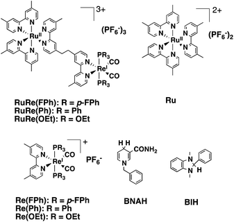 |
| | Chart 1 Structures and abbreviations of the Ru(II)–Re(I) binuclear complexes, the model complexes of their subunits (Ru and Re(X)), BNAH, and BIH. | |
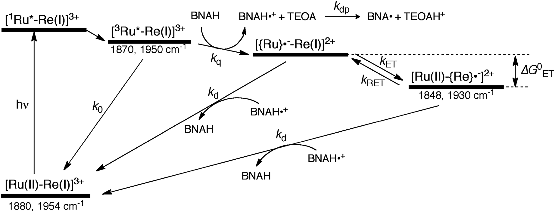
The mechanism for the photochemical generation of the one-electron reduced species (OERS) of the Ru(II)–Re(I) supramolecular catalysts has been proposed as follows (Scheme 1(a), reductive quenching mechanism9): (Process 1) selective light absorption of the Ru photosensitizer unit giving its triplet metal-to-ligand charge transfer (3MLCT) excited state, i.e., [3Ru*–Re(I)]3+; (Process 2) reductive quenching of the 3MLCT excited state by a reductant (Q) giving the OERS of the photosensitizer unit, i.e., [{Ru}˙−–Re(I)]2+; and (Process 3) intramolecular electron transfer from the OERS of the photosensitizer unit to the Re catalyst unit giving the OERS of the catalyst unit, i.e., [Ru(II)–{Re}˙−]2+. This is followed by Process 4 (not shown in Scheme 1), i.e., CO2 reduction with the OERS or other reduced Re species derived from the OERS, giving CO. Although transient emission and UV-vis absorption spectroscopies have been applied to mechanistic investigations of these systems, only very limited information was obtained mainly because the three important transient species, i.e., the 3MLCT excited state, the OERS of the photosensitizer unit, and the OERS of the catalyst unit, have similar broad absorptions in the visible and near-IR regions, mainly corresponding to the anion radical of the diimine ligand.7,10,16 We need to be able to monitor the transient behaviour of these species separately, especially the rate constant of the intramolecular electron transfer from the OERS of the photosensitizer unit to the catalyst unit, which is one of the key processes of the photocatalytic reactions as described above.
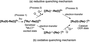 |
| | Scheme 1 Reductive and oxidative pathways in the photochemical formation of the OERS of RuRe(X). | |
Time-resolved infrared (TRIR) spectroscopy is a powerful method for addressing the above mentioned problem, since IR vibrational bands are usually narrow and their frequencies are very sensitive to changes in electronic density at the metal centre in transition metal complexes.17–20 In particular, various transient species of Re diimine carbonyl complexes, whose carbonyl ligands exhibit strong IR stretching bands, have been investigated in detail using TRIR.19,21,22 For example, the νCO bands of cis,trans-[Re(bpy)(CO)2{P(OEt)3}2]+ (1881 and 1956 cm−1) are shifted about 30 cm−1 to lower energy upon one-electron reduction of the bpy ligand, i.e., cis,trans-[Re(bpy˙−)(CO)2{P(OEt)3}2] (1852 and 1928 cm−1) in CH3CN, due to additional electron density at the Re centre and an increase in π backbonding into the π* antibonding orbitals of the CO ligands.23 Excited states of several dyads have also been investigated using TRIR spectroscopy.24–38 Perutz, George, and coworkers reported TRIR spectra of binuclear complexes consisting of a metal porphyrin photosensitizer and a fac-[Re(BL)(CO)3(pic)]+-type complex (pic = 3-picoline), which were connected by a carboxyamidylphenyl bridging ligand (BL), and successfully observed rapid photochemical intramolecular electron transfer events to make a charge separated state.28,35,36 However, they did not clearly observe formation of the one-electron reduced binuclear complex by TRIR with single-shot excitation, even in the presence of triethanolamine as a reductant, and could not determine the rate of intramolecular electron transfer from the reduced porphyrin unit to the Re-complex unit. Although a few other groups have also reported photochemical electron transfer in systems consisting of other porphyrins,29 organic dye,31,34 or polyoxometalate37,38 and a Re(I)-complex unit, intramolecular electron transfer events from the reduced unit in the ground state to the Re unit were not reported.
In the Ru(II)–Re(I) supramolecular photocatalysts, there is no strong electronic interaction between the Ru and Re units due to the non-conjugated bridging group (the ethylene linker). This should also assist selective measurement of TRIR changes of the Re catalyst unit in the photochemical reactions in the absence and presence of an electron donor.
Here we report, for the first time, TRIR spectra of three Ru(II)–Re(I) supramolecular photocatalysts, RuRe(X) (Chart 1: X = FPh, Ph, OEt), in the absence and presence of a reductant (BNAH, Scheme 1), following selective photoexcitation of the Ru unit. The TRIR data have afforded new and important information about processes 1–3 in Scheme 1.
2 Results and discussion
2.1. Excitation of RuRe(X) in the absence of a reductant
In the photocatalytic reactions using RuRe(X), reductive quenching (RQ) of the excited Ru unit by a reductant (Scheme 1(a)) has been proposed as an initiating process of the photo-catalytic reduction of CO2 because the oxidizing power and emission lifetime of the excited Ru unit are similar to those of the corresponding model mononuclear Ru(II) complex (Ru) shown in Chart 1, i.e., [Ru(dmb)3]2+ (dmb = 4,4′-dimethyl-2,2′-bipyridine).7,10 However, there has been no direct evidence showing whether or not intramolecular oxidative quenching of the excited Ru unit by the Re unit (Scheme 1(b)) can occur as another possible initiating process. To clarify this issue, we have measured TRIR spectra of RuRe(X) in the absence of a reductant.
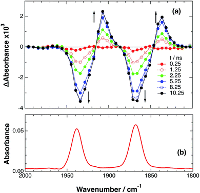
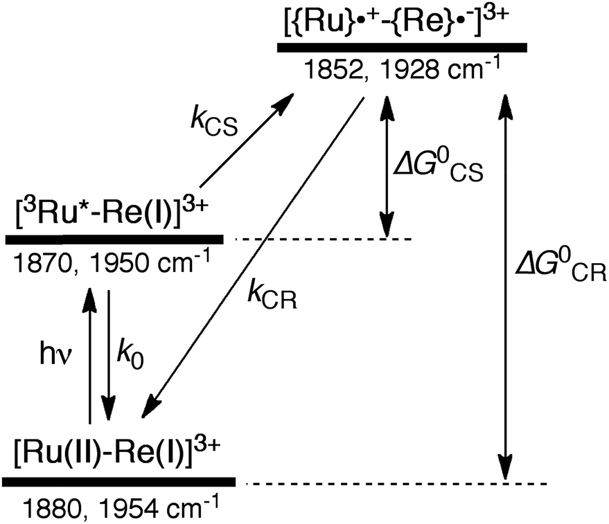
An acetonitrile solution containing only RuRe(X) (2 mM) was irradiated with a 532 nm laser pulse, which can only be absorbed by the Ru(II) unit. As a typical example, Fig. 1 shows TRIR spectra recorded in the region of the νCO vibrations of the CO ligands of RuRe(OEt) (1800–1975 cm−1). Immediately after the laser excitation (shown as 0.00 μs), two negative bleach bands attributed to the ground state of the Re(I) unit at 1880 cm−1 and 1954 cm−1, and two new absorption bands at lower wavenumbers (1870 and 1950 cm−1) were observed simultaneously. The excited Ru(II) unit should relax to the 3MLCT excited state within the duration of the laser pulse (∼5 ns), and the excited electron should mainly reside in the π* orbitals of the diimine ligands, which consist of two peripheral dmb ligands and one bridging ligand. Since the energies of the π* orbitals of these three diimine ligands are similar to each other, the excited electron will migrate among these three ligands in the 3MLCT excited state (probably on the time scale of several hundreds of picoseconds).39,40 Note that in the case of reduced Re carbonyl complexes, shifts of the νCO bands to lower energy relative to the non-reduced complexes are typically much larger (25–40 cm−1) than those seen immediately after the laser pulse in Fig. 1 (∼≤ 10 cm−1).23,41–43 Therefore, we attribute our observation of much smaller low-energy shifts of the νCO bands to a smaller increase in the electron density at the Re(I) metal centre induced by a weak electronic interaction with the excited Ru unit through the bridging ligand, which has partially accepted the excited electron. Thus, we can conclude that the νCO bands of the Re unit in the excited RuRe(OEt), in which the Ru unit is in its lowest 3MLCT excited state, are located at 1870 and 1950 cm−1 (Scheme 2). It should be noted that these absorption maxima are not exact values because of overlap with the decrease of the ground state absorptions of the RuRe(OEt). This 3MLCT excited state was the main transient species present for up to a few hundred nanoseconds after the laser excitation.
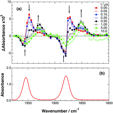 |
| | Fig. 1 (a) TRIR spectra (ns-system) recorded after 532 nm excitation of RuRe(OEt) (2 mM) in an argon-saturated CH3CN solution. (b) FT-IR spectrum of RuRe(OEt) in CH3CN. | |
 |
| | Scheme 2 Photoexcitation and the subsequent relaxation processes of a [Ru(II)–Re(I)]3+ binuclear complex in the absence of any quencher molecules in solution, i.e., the formation of a triplet metal-to-ligand charge transfer excited state ([3Ru*–Re(I)]3+) followed by a charge-separated state ([{Ru}˙+–{Re}˙−]3+) due to electron transfer from the Ru unit to the Re unit. Wavenumber values shown are for the RuRe(OEt) complex. | |
As can be seen in Fig. 1, the lowest 3MLCT excited state of the Ru unit completely disappeared by 1 μs after excitation, and two new bands simultaneously grew in to lower frequencies (1852 and 1928 cm−1). The magnitudes of the red-shifts of these νCO frequencies relative to the non-reduced ground state of the Re(I) unit (28 and 26 cm−1) are typical of the one-electron reduction of Re(I) diimine complexes.17,23,41 Therefore, the charge-separated state of RuRe(OEt), which consists of the OERS of the Re unit and a one-electron-oxidized species (OEOS) of the Ru unit, forms on the submicrosecond time scale.
Similar TRIR spectra were observed for the other Ru(II)–Re(I) complexes (Fig. S1 and S2,†Table 2). Therefore, our data confirm that intramolecular oxidative quenching of the excited Ru unit by the Re unit does occur, producing the charge separated state in RuRe(X). However, it is a very slow process. For a kinetic analysis of not only the photoinduced charge separation process, but also the charge recombination process, the relaxation model shown in Scheme 2 was assumed and the time profiles of each peak in the TRIR spectra were analysed as discussed below.
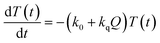
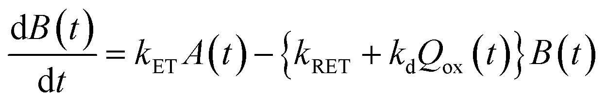
In the time scale of our TRIR measurements (20 ns to ∼100 μs), the 3MLCT excited state can be regarded as a single excited state owing to the rapid electron hopping among the three diimine ligands on a time scale of <1 ns as described above.39,40 In this analysis, therefore, three electronic states, i.e., the ground state ([Ru(II)–Re(I)]3+), the 3MLCT excited state of the Ru unit ([3Ru*–Re(I)]3+), and the charge-separated state ([{Ru}˙+–{Re}˙−]3+) were employed for the calculation (Scheme 2). The temporal behaviours of these states can be described by the following rate equations,
| |  | (1) |
| |  | (2) |
| | | G0 − G(t) = T(t) + C(t) | (3) |
where the symbols are defined as follows,
T(
t): concentration of [
3Ru*–Re(
I)]
3+ at
t seconds after the laser flash,
C(
t): concentration of [{Ru}˙
+–{Re}˙
−]
3+ at
t seconds after the laser flash,
G(
t): concentration of [Ru(
II)–Re(
I)]
3+ (the ground state) at
t seconds after the laser flash,
G0: concentration of [Ru(
II)–Re(
I)]
3+ used in the experiment,
k0: total rate constant for decay processes of [
3Ru*–Re(
I)]
3+ except for the intramolecular electron transfer process,
kCS: forward electron-transfer rate constant (charge separation) in [
3Ru*–Re(
I)]
3+, and
kCR: backward electron-transfer rate constant (charge recombination) in [{Ru}˙
+–{Re}˙
−]
3+.
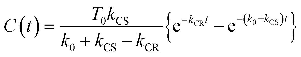
Assuming an initial concentration of [3Ru*–Re(I)]3+ (T0), the set of rate equations (eqn (1)–(3)) can be analytically solved and the concentrations of [3Ru*–Re(I)]3+ (T(t)) and [{Ru}˙+–{Re}˙−]3+ (C(t)) are represented by the functions below.
| | | T(t) = T0e−(k0 + kCS)t | (4) |
| |  | (5) |
The TRIR absorbance change (ΔA) at the monitoring wave-number (ν) at time, t after the laser flash is described by the sum of the contributions from the three components, i.e., G(t), T(t), and C(t) as shown in eqn (6), where εG(ν), εT(ν), and εC(ν) are the absorption coefficients of [Ru(II)–Re(I)]3+, [3Ru*–Re(I)]3+, and [{Ru}˙+–{Re}˙−]3+, respectively, and d is the cell path length (d = 1.9 mm).
| | | ΔA(v,t) = εT(v)T(t)d + εC(v)C(t)d − εG(v){T(t) + C(t)}d = {εT(v) − εG(v)}T(t)d + {εC(v) − εG(v)}C(t)d | (6) |
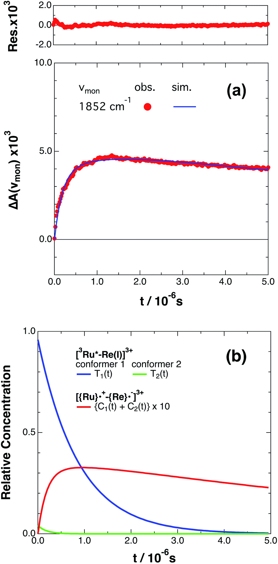
If the photophysical processes proceed exactly as described in Scheme 2, for instance in the case of RuRe(OEt), the TRIR absorbance observed at ν1 = 1852 cm−1 (Fig. 2a), which is dominated by the charge-separated state absorption ([{Ru}˙+–{Re}˙−]3+), would be represented by the sum of the exponential rise component with a summated rate constant (k0 + kCS), and the exponential decay component with a rate constant of kCR (eqn (5)). However, the observed TRIR absorption rise and decay could not be well-fitted with a double exponential function (Fig. S5†), instead requiring a triple exponential function for a good fit, as described below in detail (Fig. 2a). At other wavelengths, the decay of the 3MLCT excited state and rise of [{Ru}˙+–{Re}˙−]3+ was also reasonably fitted with a triple exponential function. Although we do not know the reason for there being two kinetically-different processes in the photoinduced intramolecular electron transfer, these results might suggest that the excited state, [3Ru*–Re(I)]3+ has at least two structural conformers, each of which has a different charge-separation rate. This is also supported by the fact that the emission decay from [3Ru*–Re(I)]3+ had two components; a major (slower) component and a minor (faster) one, and could be well-fitted by a double exponential function as shown in Fig. S6a–c.† The emission decay rate constants, k1 and k2 (Table 4) were the same as two sums of the decay rate constants (k0 + kCS1 and k0 + kCS2) obtained by the TRIR measurements described above within the experimental errors, respectively (Table 2).
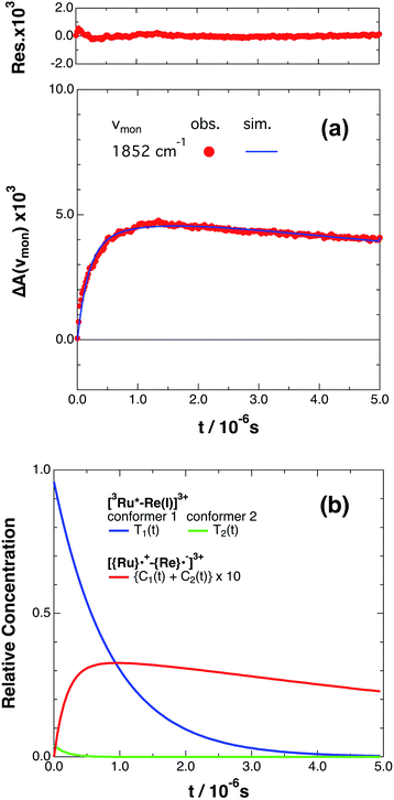 |
| | Fig. 2 (a) Growth and decay of the transient infrared absorption band of RuRe(OEt) in CH3CN, monitored at 1852 cm−1 ( ) after 532 nm excitation. The corresponding simulated absorbance change obtained from eqn (8) is shown as a solid curve. Top panel shows the residual obtained from the simulation. (b) Calculated relative concentrations of [3Ru*–Re(I)]3+ of conformers 1 and 2 (blue and green lines) and [{Ru}˙+–{Re}˙−]3+ (red line, plotted at ten times the calculated amount) as a function of time. ) after 532 nm excitation. The corresponding simulated absorbance change obtained from eqn (8) is shown as a solid curve. Top panel shows the residual obtained from the simulation. (b) Calculated relative concentrations of [3Ru*–Re(I)]3+ of conformers 1 and 2 (blue and green lines) and [{Ru}˙+–{Re}˙−]3+ (red line, plotted at ten times the calculated amount) as a function of time. | |
The optical and electronic properties of these conformers of [3Ru*–Re(I)]3+, except their charge-separation rates (kCS1 and kCS2), can be reasonably assumed to be similar to one another. For example, their absorption spectra and extinction coefficients in the UV-vis and IR regions should be similar, because the interaction between each unit in the binuclear complexes is weak. Therefore, the observed TRIR absorbance changes should be evaluated as the sum of the contributions from each conformer. According to these investigations, the TRIR absorbance change (ΔA(ν1,t)) of the peak attributed to [{Ru}˙+–{Re}˙−]3+, for example at ν1 = 1852 cm−1 for RuRe(OEt), can be described by eqn (7) because the peak of the ground state and the 3MLCT excited state are located at 20–30 cm−1 higher wavenumbers than ν1 and thus their contributions should be negligible, i.e., εG(ν1) ≈ 0 and εT(ν1) ≈ 0 in eqn (6).
| | | ΔA(v1,t) = εC(v1){C1(t) + C2(t)}d | (7) |
where
C1(
t) and
C2(
t) are the concentrations of [{Ru}˙
+–{Re}˙
−]
3+ produced from the two conformers of [
3Ru*–Re(
I)]
3+. Combining
eqn (4),
(5), and
(7), the temporal profile of the TRIR absorption should be represented by the triple exponential function below.
| |  | (8) |
where
β is the initial mole fraction of the minor conformer of [
3Ru*–Re(
I)]
3+. The TRIR absorption decay observed at 1852 cm
−1, which is due to [{Ru}˙
+–{Re}˙
−]
3+ for
RuRe(OEt), could be fitted well using
eqn (8) (
Fig. 2a, see Experimental section for details). A similar triple-exponential function which has the same rate constants (
kCS1,
kCS2 and
kCR) as
eqn (8) could also simulate the absorbance change at 1872 cm
−1, which is mostly due to [
3Ru*–Re(
I)]
3+ (Fig. S3
†). Based on these analyses, the concentration changes of both the
3MLCT excited state (
T1(
t),
T2(
t)) and the charge separated state (C
1(
t) + C
2(
t)) were calculated as shown in
Fig. 2b. Similar analyses were successfully applied to the TRIR results of the other complexes (Fig. S4,
†Table 1).
Table 1
ν
CO IR absorption bands and molar extinction coefficients measured in argon-saturated CH3CN solutions at 298 K
| Complex |
[Ru(II)–Re(I)]3+a |
[3Ru*–Re(I)]3+a,b |
[{Ru}˙+–{Re}˙−]3+c |
[Ru(II)–{Re}˙−]2+d |
|
ν
CO/cm−1 (εGe/103 M−1 cm−1) |
ν
CO/cm−1 |
ν
CO/cm−1 (εCf/103 M−1 cm−1) |
ν
CO/cm−1 (εBf/103 M−1 cm−1) |
Transient absorption and bleaching maximum wavenumbers observed immediately after laser irradiation.
These values might deviate from the exact absorption maxima of [3Ru*–Re(I)]3+ due to overlap of the absorption bands of [Ru(II)–Re(I)]3+ and [3Ru*–Re(I)]3+.
Peak maximum wavenumbers observed 5 μs after laser irradiation of CH3CN–TEOA (5![[thin space (1/6-em)]](https://www.rsc.org/images/entities/char_2009.gif) :1 v/v) solutions in the absence of BNAH.
Transient absorption maximum wavenumbers observed in CH3CN–TEOA (5:1 v/v) solutions containing BNAH (0.2 M).
Calculated from the absorbance of the IR bands in the FTIR absorption spectrum, the resolution of which was 2 cm−1.
Calculated from a comparison of the ground-state bleaching and the absorption bands of the target species in the TRIR absorption spectrum. :1 v/v) solutions in the absence of BNAH.
Transient absorption maximum wavenumbers observed in CH3CN–TEOA (5:1 v/v) solutions containing BNAH (0.2 M).
Calculated from the absorbance of the IR bands in the FTIR absorption spectrum, the resolution of which was 2 cm−1.
Calculated from a comparison of the ground-state bleaching and the absorption bands of the target species in the TRIR absorption spectrum.
|
|
RuRe(OEt)
|
1880 (2.92) |
1954 (2.83) |
∼1870 |
∼1950 |
1852 (4.1) |
1928 (2.9) |
1848 (2.8) |
1930 (3.2) |
|
RuRe(Ph)
|
1866 (2.96) |
1936 (2.36) |
∼1860 |
∼1930 |
1836 (2.3) |
1906 (2.0) |
1834 (2.8) |
1906 (2.2) |
|
RuRe(FPh)
|
1870 (3.03) |
1940 (2.44) |
∼1860 |
∼1930 |
1836 (2.8) |
1910 (2.2) |
1838 (2.4) |
1912 (1.8) |
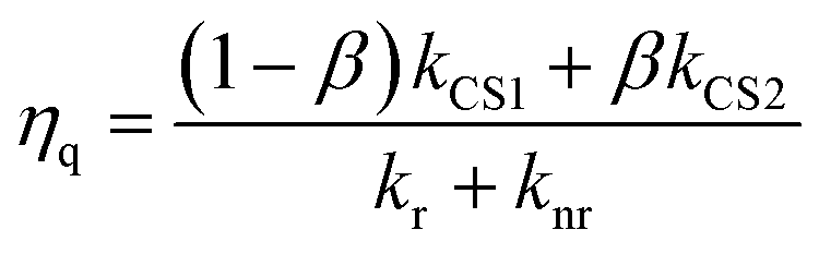
The calculated kinetic data based on these results are summarized in Table 2. The faster formation of the charge separated state (kCS2 = (3.5–4.3) × 106 s−1) is a very minor component (3–5%), while the slower one (kCS1 = (1.0–1.1) × 104 s−1) dominates. By using these data and eqn (9), the fraction of the [3Ru*–Re(I)]3+ excited state that is intramolecularly oxidatively quenched can be calculated as ηq = 3–5% in the absence of a reductant (Table 2).
| | 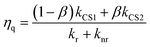 | (9) |
Table 2 Emission lifetimes (τem) and quantum yields (φem) for the 3MLCT excited state of the Ru unit, and rate constants of electron transfer from the excited Ru unit to the Re unit (kCS), back electron transfer (kCR), radiative decay (kr), and non-radiative decay (knr), all in the absence of a reductant
| Complex |
τ
em
/ns |
ϕ
em
|
Rate constant/104 s−1 |
β
|
η
q
|
|
k
r
|
k
nr
|
k
CS1
|
k
CS2
|
k
CR
|
|
From ref. 10, the emission lifetimes were obtained from single-exponential fits; measured in DMF at 298 K; k0 = 1/τem.
k
r and knr were calculated from the observed emission parameters and the following equations, i.e., τem = 1/(kr + knr), ϕem = kr/(kr + knr), and knr ≈ k0 − kr + kCS1.
Initial mole fraction of the minor conformer of [3Ru*–Re(I)]3+.
Intramolecular oxidative quenching fraction of the 3MLCT excited state of the Ru unit by the Re unit (eqn (9)).
|
|
RuRe(OEt)
|
858 |
0.082 |
9.6 |
105 |
1.0 ± 0.1 |
430 ± 130 |
11 ± 4 |
(4 ± 2)% |
(4 ± 2)% |
|
RuRe(Ph)
|
867 |
0.075 |
8.7 |
106 |
1.1 ± 0.1 |
350 ± 20 |
7 ± 1 |
(5 ± 2)% |
(5 ± 1)% |
|
RuRe(FPh)
|
853 |
0.082 |
9.6 |
105 |
1.0 ± 0.1 |
350 ± 140 |
15 ± 2 |
(3 ± 1)% |
(3 ± 1)% |
In the photocatalytic reactions, the reductant efficiently quenches the 3MLCT excited state of the Ru unit, with kq[reductant] = (3.5–3.8) × 106 s−1 (BNAH, 0.2 M) and (7.2–8.0) × 108 s−1 (BIH, 0.2 M) as discussed in detail later. The main component of the intramolecular oxidative quenching is much slower than these intermolecular reductive quenching processes. Although the minor faster process of the oxidative quenching might compete with the reductive quenching process in the case of BNAH as the reductant, the contribution should only be equal to or less than 2% of all the decay processes of [3Ru*–Re(I)]3+, and it is only about 0.2% in the case of BIH. Owing to these investigations, we can conclude that the contribution from the intramolecular oxidative quenching processes is negligible in the photocatalytic reduction of CO2 using RuRe(X) as described below.
On a timescale of 20 μs after laser excitation, the charge-separated state decays back to the ground state by first order kinetics and the rate constants of this backward electron-transfer (ETCR) process were found to be kCR = (0.7–1.5) × 105 s−1 for the three complexes investigated (Fig. 2 and S4,†Table 2).
The cyclic voltammograms of RuRe(X) and the corresponding mononuclear model complexes have been reported,10 where the Ru(2+/+) and Re(+/0) redox potentials of RuRe(X) (E0(Ru2+/Ru+) and E0(Re+/Re0), respectively) could not be exactly determined because of overlapping peaks. However, since there is only weak electronic interaction between the Ru and Re units through the non-conjugated ethylene linker, these potentials should be similar to those of the corresponding mononuclear complexes, i.e., Ru and Re(X) (Chart 1). Therefore, we employed the redox potentials of Ru and Re(X) as approximate values for each unit of RuRe(X). In contrast, it has been reported that the Ru(3+/2+) redox potentials of RuRe(X) (E0(Ru3+/Ru2+)) could be obtained from cyclic voltammograms owing to no overlapping peaks. Table 3 summarizes these redox potentials of the ground states of RuRe(X), Ru, and Re(X). The redox potentials of the lowest 3MLCT excited states of the Ru units, i.e., Ru(3+/2+*) (E0(Ru3+/Ru2+*)) were evaluated by eqn (10).
| | | E0(Ru3+/Ru2+*) = E0(Ru3+/Ru2+) − E00(3Ru*) | (10) |
where
E00(
3Ru*) is the excitation energy of the lowest
3MLCT excited state of the Ru unit of
RuRe(X), which was obtained by Frank–Condon analysis (Fig. S10
†).
44,45
Table 3 Redox potentials of the metal complexes, excitation energies, and thermodynamic data for the intramolecular electron transfer process from the excited Ru unit to the Re unit and the ETCR process
| Complex |
E
0/V vs. Ag/AgNO3 |
E
00(3Ru*)b/eV |
−ΔG0CS/eV |
−ΔG0CR/eV |
| Ru(3+/2+)a |
Ru(3+/2+*) |
Ru(2+/+)a |
Re(+/0)a |
|
From ref. 10; measured in an CH3CN solution containing the complex (0.6 mM) and Et4NBF4 (0.1 M).
Excitation energy of the lowest 3MLCT excited state of the Ru unit (Fig. S10).
|
|
RuRe(OEt)
|
0.81 |
−1.14 |
|
|
1.95 |
−0.69 |
2.65 |
|
RuRe(Ph)
|
0.81 |
−1.14 |
|
|
1.95 |
−0.68 |
2.64 |
|
RuRe(FPh)
|
0.83 |
−1.12 |
|
|
1.95 |
−0.61 |
2.56 |
|
Ru
|
0.82 |
|
−1.74 |
|
|
|
|
|
Re(OEt)
|
|
|
|
−1.78 |
|
|
|
|
Re(Ph)
|
|
|
|
−1.77 |
|
|
|
|
Re(FPh)
|
|
|
|
−1.67 |
|
|
|
According to the investigation described above, the free energy changes of the intramolecular electron transfer process from the excited Ru unit to the Re unit (−ΔG0CS) and the ETCR process (−ΔG0CR) were evaluated using the electrochemical data, E00(3Ru*), and eqn (11)–(13).46,47
| | | −ΔG0CS = −E0(Ru3+/Ru2+*) + E0(Re+/Re0) + wp | (11) |
| | | −ΔG0CR = E0(Ru3+/Ru2+) − E0(Re+/Re0) − wp | (12) |
| |  | (13) |
where the symbols are defined as follows,
wp: coulombic term corresponding to the electron-transfer processes,
Zx: charge of the donor and acceptor species x,
e: elementary charge,
ε0: permittivity of vacuum,
εS = 37.5 (the solvent dielectric constant of CH
3CN),
48dcc = 1.38 nm: distance between the Ru and Re metal centres in the energy-minimized structure of the ground state molecule calculated by an MM2 force field calculation using Chem3D v. 12.0, Cambridge Soft Corporation.
These thermodynamic data are also summarized in Table 3. The highly endergonic free energy change of the intramolecular electron transfer process from the excited Ru unit to the Re unit (−ΔG0CS ∼ −0.7 eV) is consistent with the experimental results, i.e., the observation of very slow intramolecular electron transfer (kCS in Table 2).49 Interestingly, the rates of the ETCR process (kCR in Table 2) were similar in magnitude to kCS in spite of their huge driving forces (−ΔG0CR ∼2.7 eV). These results clearly indicate that the ETCR processes in all RuRe(X) are in the Marcus inverted region.
The backward electron-transfer could, in principle, also produce the excited state, i.e., [3Ru*–Re(I)]3+, since this should be an exergonic process. However, this did not happen, as evidenced by the fact that the emission decay from [3Ru*–Re(I)]3+ could be perfectly analysed by a double exponential function for all of RuRe(X), with kem = 1.1 × 10⁶ s−1 (major component) and kem = (7–8) × 106 s−1 (minor component), and no prolonged emission was observed with a rate constant similar to that of the decay process of the charge separated state, i.e., [{Ru}˙+–{Re}˙−]3+, (kCR = (0.7–1.5) × 105 s−1), as would be expected if backward electron-transfer to the excited state did occur.
2.2. Excitation of RuRe(X) in the presence of a reductant
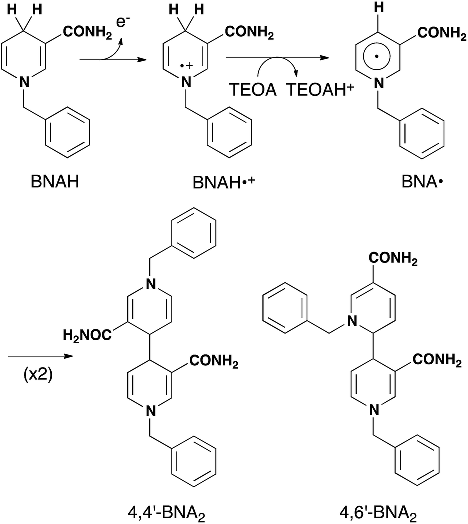
As described above, photocatalytic CO2 reduction using Ru(II)–Re(I) supramolecular photocatalysts is initiated by a reductive quenching (RQ) process of the lowest 3MLCT excited state of the Ru photosensitizer unit by a reductant (Scheme 3). In the reported photocatalytic CO2 reduction, 1-benzyl-1,4-dihydronicotinamide (BNAH) has often been employed as the reductant. Table 4 summarizes the emission properties of RuRe(X) and the rate constants of the RQ process of the 3MLCT excited state of the Ru unit by BNAH. BNAH can effectively quench the excited Ru(II) unit because of its strong reducing power (E0 = 0.57 V vs. SCE (BNAH˙+/BNAH)).50 It has been reported that the photochemically produced BNAH˙+ is deprotonated in the presence of a base such as TEOA, giving BNA˙ as shown in eqn (14). In the photocatalytic reactions using Ru(II)–Re(I) supramolecular photocatalysts, quantitative coupling of BNA˙ occurs, giving the corresponding dimers (4,4′-BNA2 and 4,6′-BNA2) (eqn (14)), thus preventing BNA˙ from acting as a reductant.10 In other words, we can expect that BNAH supplies only one electron to the Ru unit after the Ru photosensitizer unit of RuRe(X) absorbs one photon.
 |
| | Scheme 3 Processes of the photochemical reaction of RuRe(X) in the presence of BNAH. Wavenumber values shown are for the RuRe(OEt) complex. | |
Table 4 Emission data for the excited Ru unit of RuRe(X) in DMF at 298 K (λex = 460 nm), and rate constants of reductive quenching (kq) of the excited Ru unit by BNAH
| Complex |
λ
em
/nm |
k
/106 s−1 |
β
|
k
q
/106 M−1 s−1 |
|
k
1
|
k
2
|
|
Emission peak wavelengths were measured in DMF at 298 K.10
Emission decay rate constants (k1 and k2) and initial abundance of the k1 component (β) were measured in CH3CN at 298 K (Fig. S6).
Quenching rate constants were calculated from the fraction of emission quenching by BNAH in DMF at 298 K.10,11
|
|
RuRe(OEt)
|
642 |
7 ± 5 |
1.11 ± 0.01 |
(4 ± 1)% |
18 |
|
RuRe(Ph)
|
642 |
8 ± 3 |
1.10 ± 0.01 |
(6 ± 1)% |
17 |
|
RuRe(FPh)
|
642 |
8 ± 7 |
1.12 ± 0.05 |
(7 ± 1)% |
19 |
In the current experiments, the concentration of BNAH used was 0.2 M, which is two times higher than that used in the previously reported photocatalytic reactions using Ru(II)–Re(I) supramolecular photocatalysts. This was done because it results in a more rapid formation of the OERS of the Ru unit. The samples were prepared as argon-saturated CH3CN–TEOA (5:1 v/v) mixed solutions containing RuRe(X) (2 mM) and BNAH (0.2 M). Note that TEOA does not reductively quench the emission from RuRe(X), but works solely as a base for deprotonation of BNAH˙+ as discussed above. It thus assists in suppressing back-electron transfer from the reduced complex to BNAH˙+.10 Under these reaction conditions, 75–77% of the emission from the 3MLCT excited state of the Ru(II) unit was quenched by BNAH.
| | 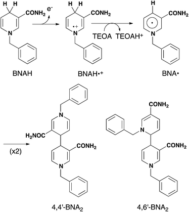 | (14) |
We can expect the processes shown in Scheme 3 after excitation of RuRe(X) in the presence of BNAH. The excitation initially produces the 1MLCT excited state of the Ru unit, which will be converted to its 3MLCT excited state via intersystem crossing within several tens – several hundreds of femtoseconds.51 The 3MLCT excited state of the Ru unit ([3Ru*–Re(I)]3+) is effectively quenched by BNAH. This is a RQ process, giving the OERS of the Ru unit ([{Ru}˙−–Re(I)]2+) and BNAH˙+, with a free energy change that is exergonic (−ΔG0 = 0.01 eV; see ESI†) for all of RuRe(X). The accepted electron localized on the Ru unit will transfer to the Re unit in the same Ru(II)–Re(I) dinuclear complex giving the OERS of the Re unit ([Ru(II)–{Re}˙−]2+). The free energy change for this electron-transfer process, −ΔG0ET can be calculated using eqn (15) and (16), and is summarized in Table 5.
| | | −ΔG0ET = −E0(Ru2+/Ru+) + E0(Re+/Re0) + wp′ | (15) |
| |  | (16) |
Table 5 Kinetic and thermodynamic data of the photochemical reactions of RuRe(X) in the presence of BNAH
| Complexes |
Rate/106 s−1 |
−ΔG0ETb/eV |
α
|
|
k
ET
|
k
RET
|
k
q
Q
|
|
Q = [BNAH] = 0.2 M.
Free energy change for the intramolecular electron transfer process calculated using eqn (15) and (16).
The ratio (α) between [{Ru}˙−–Re(I)]2+ and [Ru(II)–{Re}˙−]2+ in the OERS of the Ru(II)–Re(I) dinuclear complex.10
|
|
RuRe(OEt)
|
2.4 |
8.0 |
3.5 |
−0.07 |
3.33 |
|
RuRe(Ph)
|
5.7 |
10.2 |
3.5 |
−0.06 |
1.75 |
|
RuRe(FPh)
|
5.8 |
0.6 |
3.8 |
0.04 |
0.082 |
The small values obtained (|ΔG0ET| < 0.1 eV) for all of RuRe(X), indicate that backward electron-transfer (kRET) should also proceed from the OERS of the Re catalyst unit to the Ru unit. Actually, such phenomena have been reported in photochemical CO2 reduction using Ru(II)–Re(I) binuclear complexes as photocatalysts, where a quasi-equilibrium between the two OERSs i.e., [{Ru}˙−–Re(I)]2+ and [Ru(II)–{Re}˙−]2+, is achieved. Evidence for this comes from the shape of the absorption band at 500–650 nm attributed to the two OERSs, which was well-simulated by a combination of those of the OERSs of the corresponding mononuclear Ru and Re complexes, and which did not change, at least for several hours.10 This equilibrium should also be achieved in the TRIR measurements.
| |  | (17) |
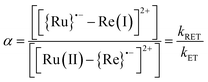
We can use the ratio between [{Ru}˙−–Re(I)]2+ and [Ru(II)–{Re}˙−]2+ (α) for determining the ratio between the backward and forward electron transfer rate constants as shown in eqn (17). The resulting α values are summarized in Table 5.
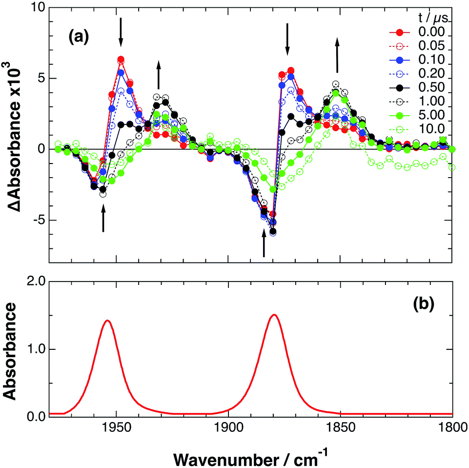
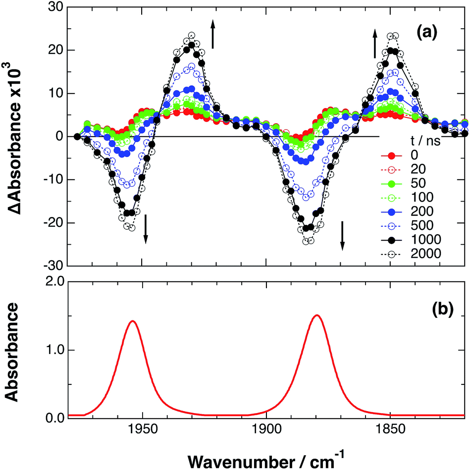
As a typical example, Fig. 3 shows TRIR spectra of Ru–Re(OEt) in the presence of BNAH at various times after laser excitation. In the first stage immediately after the laser pulse (typically t = 20–50 ns), weak absorption bands at νCO = 1870 cm−1 and 1950 cm−1 and bleaching bands at νCO = 1886 cm−1 and 1960 cm−1 were observed. The former absorption bands decrease on the time scale of several hundreds of nanoseconds, which is similar to the time scale of the RQ process of the 3MLCT state of the Ru unit by BNAH, which was calculated by eqn (18).
| | | τ = 1/(k0 + kq[BNAH]) = 1/(4.7 × 106) ≈ 210 ns | (18) |
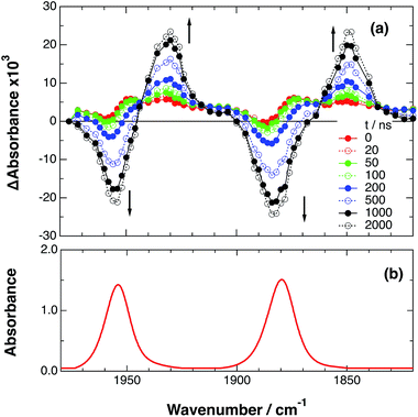 |
| | Fig. 3 (a) TRIR spectra (ns-system) recorded after 532 nm excitation of RuRe(OEt) (2 mM) in argon-saturated CH3CN/TEOA (5:1 v/v) containing 0.2 M BNAH. (b) FT-IR spectrum of RuRe(OEt) in CH3CN. | |
Combining this observation with the experimental results in the absence of reductants, which are described in the previous section, enables us to attribute the bands at νCO = 1870 and 1950 cm−1 to the excited state [3Ru*–Re(I)]3+, and those at 1886 and 1960 cm−1 to the ground state [Ru(II)–Re(I)]3+, which were slightly different from those measured by FTIR because of the band overlapping as described above. The bleaching bands grew with a very slight red-shift until several microseconds after laser excitation, when intense bleaching bands were observed at νCO = 1880 and 1954 cm−1. New absorption bands at νCO = 1848 cm−1 and 1930 cm−1, even more red-shifted compared to the 3MLCT excited state bands, appeared on the same time scale as the growth of the bleaching bands. These new absorption bands are attributed to the formation of the OERS of the Re unit, i.e., [Ru(II)–{Re}˙−]2+, since the magnitudes of their shifts from the non-reduced ground state bands are similar to those previously observed for related mononuclear Re complexes.23,41 Similar TRIR spectral changes were observed in the cases of the other RuRe(X) on similar time scales (Fig. S7 and S8†). The data for the IR absorption bands are summarized in Table 1.
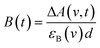
Only two transient species, [{Ru}˙−–Re(I)]2+ and [Ru(II)–{Re}˙−]2+, should remain at 5.0 μs after the laser excitation because the lifetime of the excited state of RuRe(OEt) is only 210 ns in the presence of 0.2 M BNAH. It can reasonably be assumed that the frequencies and absorbance values of the νCO bands of [{Ru}˙−–Re(I)]2+ should be much closer to those of the non-reduced ground state than the νCO bands of [Ru(II)–{Re}˙−]2+, due to the weak electronic interaction between the Ru and Re units via the saturated ethylene chain. Based on our TRIR data, we can estimate the amount of [Ru(II)–{Re}˙−]2+ formed using the absorbance of the negative peaks at 1880 cm−1 and 1954 cm−1 and the molar extinction coefficients of the non-reduced ground state at these wavenumbers, obtained from FTIR measurements. Using these data, the molar extinction coefficients of the νCO bands of [Ru(II)–{Re}˙−]2+ (εB(ν)) were estimated as 2.8 × 10³ M−1 cm−1 at 1848 cm−1 and 3.2 × 10³ M−1 cm−1 at 1930 cm−1 in the case of RuRe(OEt). A similar procedure was applied to the other complexes, and the data are summarized in Table 1. The concentration of [Ru(II)–{Re}˙−]2+ (B(t)) was calculated by using eqn (19) and the observed ΔA value at ν cm−1 at time = t after the laser excitation, where d = cell path length (1.9 mm).
| |  | (19) |
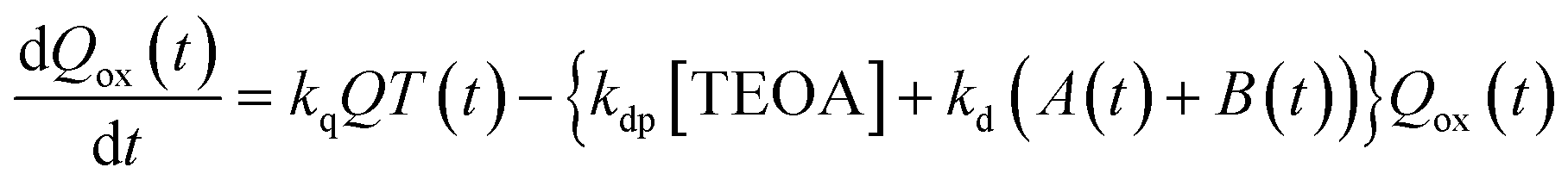
Now, we can analyse the kinetics of the photochemistry of RuRe(X) in the presence of BNAH according to the mechanism shown in Scheme 3. After laser excitation, three different electronic species, i.e., the 3MLCT excited state of the Ru unit ([3Ru*–Re(I)]3+), the OERS of the Ru unit ([{Ru}˙−–Re(I)]2+), and the OERS of the Re unit ([Ru(II)–{Re}˙−]2+), are formed. Their concentrations can be represented by the following rate equations, where the concentrations of [3Ru*–Re(I)]3+, [{Ru}˙−–Re(I)]2+, [Ru(II)–{Re}˙−]2+, and the one-electron oxidized product of the quencher molecule (BNAH˙+) at time t are abbreviated as T(t), A(t), B(t), and Qox(t), respectively,
| |  | (20) |
| |  | (21) |
| |  | (22) |
| |  | (23) |
where the symbols are defined as follows,
Q: initial concentration of BNAH,
i.e., 0.2 M,
k0: decay rate constant of [
3Ru*–Re(
I)]
3+;
kq: quenching rate constant of [
3Ru*–Re(
I)]
3+ by BNAH;
kET: forward electron transfer rate constant;
kRET: backward electron transfer rate constant;
kd: recombination rate constant between the one-electron oxidized quencher radical and the OERS;
kdp: rate constant of deprotonation of BNAH˙
+ by TEOA.
The set of rate equations (eqn (20)–(23)) were numerically solved by using the non-linear model fit method in the Wolfram Mathematica 10 software (Wolfram Research Inc.) to minimize the deviation of the evaluated ΔA values from those in the TRIR data, with the parameters of k0, kq, and α obtained as described above. Typical fitting data in the case of RuRe(OEt) are shown in Fig. 4 and the others are in Fig. S9.† The evaluated kinetic parameters are summarized in Table 5.
 |
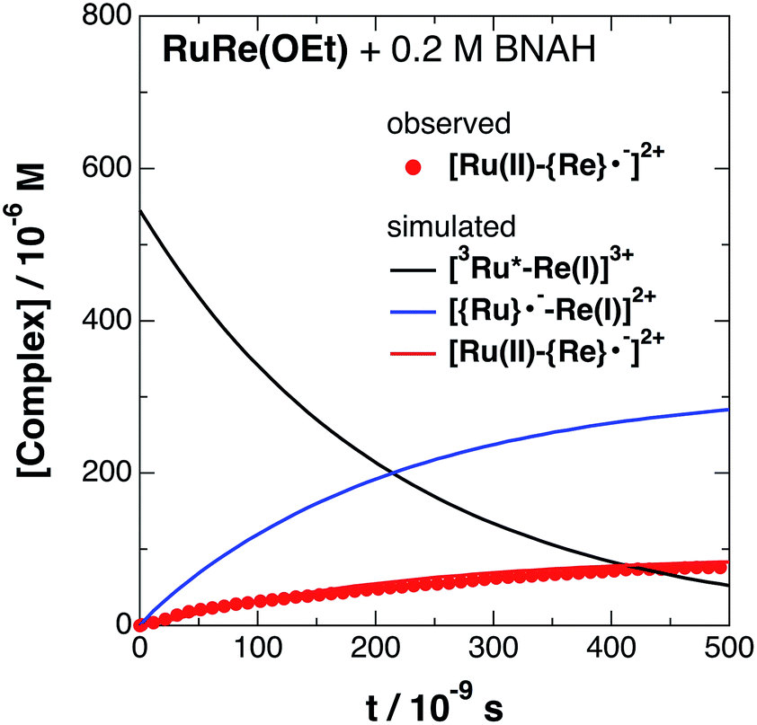
| | Fig. 4 Time profile of [Ru(II)–{Re}˙−]2+ ( ) in the TRIR measurement of RuRe(OEt) in the presence of 0.2 M BNAH in an argon-saturated CH3CN/TEOA (5:1 v/v) solution after 532 nm excitation. The kinetic simulation results for [3Ru*–Re(I)]3+, [{Ru}˙−–Re(I)]2+, and [Ru(II)–{Re}˙−]2+ are also shown (solid lines). ) in the TRIR measurement of RuRe(OEt) in the presence of 0.2 M BNAH in an argon-saturated CH3CN/TEOA (5:1 v/v) solution after 532 nm excitation. The kinetic simulation results for [3Ru*–Re(I)]3+, [{Ru}˙−–Re(I)]2+, and [Ru(II)–{Re}˙−]2+ are also shown (solid lines). | |
The obtained forward electron transfer rate constants, kET, were (2.4–5.8) × 106 s−1, which are very similar to the pseudo-first order rate constants for RQ of the 3MLCT excited state of RuRe(X) by BNAH (0.2 M), i.e., kq[BNAH] = (3.5–3.8) × 106 s−1. These consistencies within experimental error clearly indicate that the rate-limiting process in the formation of [Ru(II)–{Re}˙−]2+ is the RQ of the excited Ru unit by BNAH, not the intramolecular electron transfer process from the OERS of the Ru unit to the Re unit. In other words, the TRIR results in the presence of BNAH show that electron transfer from the OERS of the Ru unit to the Re unit should occur on a time scale that is much shorter than several microseconds. This rapid intramolecular electron transfer from the reduced photosensitizer, which is produced by the photochemical reduction, to the Re catalyst unit is one of the most important advantages of the Ru(II)–Re(I) supramolecular photocatalysts with the saturated ethylene linker between each unit.52
A higher quenching rate would be required to determine the “real” rate constant of the intramolecular electron transfer event itself. We tried to achieve this by using 1,3-dimethyl-2-phenyl-2,3-dihydro-1H-benzo[d]imidazole (BIH), which is a stronger reductant than BNAH (E0(BIH˙+/BIH) = 0.04 V, while E0(BNAH˙+/BNAH) = 0.28 V vs. Ag/AgNO3),11 because usage of a concentration of BNAH much higher than 0.2 M is difficult in the reaction solution. However, the time resolution of our ns-TRIR system (∼50 ns with the 20 MHz bandwidth of the IR detector) was still not sufficient to measure the increase of the OERS of the Re unit in the presence of 0.2 M of BIH (Fig. S12†). This indicates that the intramolecular electron transfer from the reduced Ru unit to the Re unit should proceed within 50 ns, i.e., kET > 2 × 10⁷ s−1.
2.3. Ultrafast TRIR measurements
To accurately measure the electron transfer events of RuRe(FPh) in the early stages after laser excitation, including a precise measurement of the value of kET, we employed a faster TRIR spectroscopy technique with a time resolution of 200 ps. Fig. 5 shows the ps-TRIR spectra of RuRe(FPh) in the absence of a reductant up to 3 ns after laser excitation at λex = 532 nm. Immediately after photoexcitation, three sets of IR bands were observed. The pair of negative peaks at 1870 and 1940 cm−1 and the positive bands at 1860 and 1930 cm−1 can be attributed to the ground state and the 3MLCT excited state of the Ru unit, respectively because of their similarity to the TRIR spectra in Fig. S2.† The newly observed positive peaks at 1905 and 1985 cm−1 rapidly decreased with τ = 1.5 ± 0.2 ns (Fig. S14a†), while the other positive peaks increased and the negative peaks partially recovered with almost the same lifetime (τ = 1.1 ± 0.2 ns) (Fig. S14b†). The peaks at 1905 and 1985 cm−1 are attributed to the 3MLCT excited state of the Re unit because the magnitude of their shift from the ground state bands is similar to previously reported high-energy shifts of the νCO bands of the 3MLCT states of related Re complexes.23 In the 3MLCT excited state, the electron density of the central Re decreases to lower the π back donation to the π* orbital of the CO bonds.23 These data clearly indicate that direct excitation of the Re unit proceeded when using 532 nm laser light, even though it should be a very minor process in comparison to photon absorption by the Ru unit. Actually, the corresponding mononuclear Re complex, Re(FPh) does exhibit a very weak absorption at wavelengths longer than 530 nm (ε532 nm = 2 M−1 cm−1, Fig. S13†), and, in the TRIR spectrum of Re(FPh) recorded after 532 nm excitation, two positive bands at 1900 and 1985 cm−1 were observed (Fig. S15†). Since the lifetime of the 3MLCT excited state of RuRe(FPh) (τ = 1.4 ± 0.2 ns) was much shorter than the emission lifetime of Re(FPh) (τ = 1046 ns), an efficient intramolecular quenching process should proceed. Furue and coworkers reported, for a similar binuclear complex, [(bpy)2Ru(BL)Re(CO)3Cl]2+ (BL = (4-Mebpy)-CH2CH(OH)CH2-(4-Mebpy), that efficient intramolecular energy transfer proceeded from the excited Re unit to the Ru unit with a rate constant (kEN) ranging from 1.7 × 10⁸ to 1.2 × 10⁹ s−1.16 Similar intramolecular energy transfer should proceed in the case of RuRe(FPh) because the 3MLCT excited state of the Ru unit increased with the same rate as the decrease of the excited Re unit as described above (Scheme 4). Notably, the partial recovery of the ground state peaks is attributable to an increase of the 3MLCT excited state of the Ru unit because the νCO bands of the 3MLCT excited state of the Ru unit ([3Ru*–Re(I)]3+) and the ground state RuRe(FPh) are similar to each other owing to the very weak electronic interaction between the Ru and Re units separated by the saturated ethylene chain.
 |
| | Fig. 5 (a) TRIR spectra (ps-system) recorded after 532 nm excitation of RuRe(FPh) (1 mM) in an argon-saturated CH3CN solution. (b) FT-IR spectrum of RuRe(FPh) in CH3CN. | |
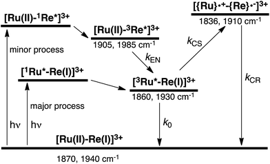 |
| | Scheme 4 Photoexcitation and the subsequent relaxation processes of a [Ru(II)–Re(I)]3+ binuclear complex in the absence of any quencher molecules in solution, i.e., the formation of a triplet metal-to-ligand charge transfer excited state ([3Ru*–Re(I)]3+ and [Ru(II)–3Re*]3+). Wavenumber values shown are for the RuRe(FPh) complex. | |
It should be noted that the absorption of Re(FPh) at λex = 532 nm is much lower than that of Ru (ε = 1223 M−1 cm−1). The formation of the excited Re unit should not affect the photochemical events of RuRe(FPh) in the presence of the electron donor described below because about 99.8% of the photons absorbed by RuRe(FPh) are absorbed by the Ru unit, and the rapid energy transfer to the Ru unit makes the lifetime of the excited Re unit very short.
In some cases of binuclear complexes consisting of metal porphyrin and Re(I) complex units, very rapid intramolecular electron transfer (within 1 ns) from the singlet excited state of the porphyrin to the Re unit was reported, as described in the Introduction section. In the case of RuRe(FPh), such rapid electron transfer was not observed; the νCO bands of the reduced Re unit of RuRe(FPh) were observed at 1836 and 1910 cm−1 (Fig. S2†). This is reasonable because the intramolecular electron transfer from the excited Ru unit to the Re unit is a thermodynamically unfavorable process (ΔG = 0.61 eV).
Fig. 6 shows ps-TRIR spectra of RuRe(FPh) in the presence of BIH after 532 nm photoexcitation. In this case, a higher concentration of BIH (0.3 M) was selected in order to increase the rate of reductive quenching of the excited Ru unit to avoid this process from becoming the rate limiting process. Thus, the pseudo-first order quenching rate constant (kq[BIH]) was 2.9 × 10⁸ s−1, since kq = 9.7 × 10⁸ M−1 s−1.11 Actually, a much faster increase of the OERS of the Re unit was observed. The time profile of the absorption at νCO = 1836 cm−1, which is attributed to the OERS of the Re unit is illustrated in Fig. 7 with fitting results using eqn (20)–(22), but with 0.3 M of BIH instead of 0.2 M of BNAH as the reductant. In the first stage of the formation of the OERS of the Re unit, an induction period was observed. This clearly indicates that the formation rate of the OERS of the Ru unit was faster than that of the OERS of the Re unit in the first stage (up to 500 ps). In other words, we can obtain the “real” rate of electron transfer from the OERS of the Ru unit to the Re unit by fitting these data. This rate constant is kET = (1.4 ± 0.1) × 109 s−1, with kRET = 1.6 × 10⁸ s−1.
 |
| | Fig. 6 (a) TRIR spectra (ps-system) recorded after 532 nm excitation of RuRe(FPh) (0.2 mM) in a DMF–TEOA (5:1 v/v) solution containing BIH (0.3 M), (b) FT-IR spectrum of RuRe(FPh) in a DMF–TEOA (5:1 v/v) solution. | |
 |
| | Fig. 7 Time profile of [Ru(II)–{Re}˙−]2+ ( ) in the ps-TRIR measurement of RuRe(FPh) in the presence of 0.3 M BIH in an argon-saturated DMF–TEOA (5:1 v/v) solution after 532 nm excitation. The kinetic simulation results for [3Ru*–Re(I)]3+, [{Ru}˙−–Re(I)]2+, and [Ru(II)–{Re}˙−]2+ are also shown (solid lines). ) in the ps-TRIR measurement of RuRe(FPh) in the presence of 0.3 M BIH in an argon-saturated DMF–TEOA (5:1 v/v) solution after 532 nm excitation. The kinetic simulation results for [3Ru*–Re(I)]3+, [{Ru}˙−–Re(I)]2+, and [Ru(II)–{Re}˙−]2+ are also shown (solid lines). | |
In the reported reactions using RuRe(FPh) as a photocatalyst for CO2 reduction, the concentration of BIH was 0.1 M,11,53i.e., kq[BIH] = 9.7 × 10⁷ s−1. Therefore, intramolecular electron transfer from the OERS of the Ru unit to the Re unit in RuRe(FPh), and probably in the other binuclear complexes too, was much faster than the reductive quenching process to form the OERS of the Ru unit. This clearly indicates that the ethylene chain is a very suitable connecting unit between a redox photosensitizer and a catalyst when designing and constructing supramolecular photocatalysts.
3 Experimental
3.1 Materials
Acetonitrile (Aldrich, Chromasolv Plus grade) was dried over activated 3 Å molecular sieves and vacuum-transferred prior to use. DMF was dried over 4 Å molecular sieves and distilled under reduced pressure (10–20 mmHg). Triethanolamine (TEOA) was distilled under reduced pressure (<1 mmHg). These were all kept under argon before use. All other reagents were reagent-grade quality and used without further purification. 1-Benzyl-1,4-dihydronicotinamide (BNAH),54,55 1,3-dimethyl-2-phenyl-2,3-dihydro-1H-benzo[d]imidazole (BIH),56,57 [(dmb)2Ru(bpyC2bpy)Re(CO)2{P(OEt)3}2](PF6)3 (dmb = 4,4′-dimethyl-2,2′-bipyridine, bpyC2bpy = 1,2-bis(4′-methyl-[2,2′-bipyridin]-4-yl)-ethane) (RuRe(OEt)),10 [(dmb)2Ru(bpyC2bpy)Re(CO)2(PPh3)2](PF6)3 (RuRe(Ph)),10 and (dmb)2Ru(bpyC2bpy)Re(CO)2{P(p-F-C6H4)3}2](PF6)3 (RuRe(FPh))10 were prepared according to reported methods.
3.2 Spectroscopic measurements
UV-vis absorption spectra were measured with a Hewlett-Packard 8452A diode-array spectrometer or a JASCO V-565 spectrophotometer. Emission spectra were measured by a JASCO FP-6500 spectrofluorometer and the emission quantum yield by a quantum yield analyser C9920-02G (HAMAMATSU). Emission lifetimes were measured using a HORIBA Jobin-Yvon FluoroCube time-correlated single photon counting system. The samples for the emission decay and quantum yield measurements were degassed by the freeze–pump–thaw method prior to the measurements. Emission-quenching experiments were performed on argon-saturated solutions containing a complex and a quencher species. Quenching rate constants, kq were evaluated from the slopes of Stern–Volmer plots of the luminescence intensity against the quencher concentration. The steady-state IR absorption spectra were measured with a Nicolet Magna 560 IR spectrometer.
3.3 Time-resolved infrared (TRIR) spectroscopy
3.3.1. ns-System.
TRIR spectroscopic measurements were performed using two CW external-cavity quantum cascade lasers (EC-QCLs), Daylight Solutions, 21052-MHF-012 (1872–1981 cm−1, 100 mW max. power) and 21058-MHF-010 (1675–1900 cm−1, 100 mW max. power) as a mid-IR monitoring light source, and the second harmonic of a pulsed Nd:YAG laser (Continuum, Powerlite 7010, 532 nm, 5 ns FWHM, 0.4–1.1 mJ per pulse at the sample) as an excitation light source. The mid-IR monitoring light generated from the EC-QCL was tuned to a proper wavelength and split into two beams; the probe and the reference beams. The probe beam was passed through a liquid IR cell and both beams were directed to a matched pair of fast rise time IR detectors (Kolmar Technologies, Inc., KMPV9-0.5-J2, DC-20 MHz). The detector signals were simultaneously digitized on an oscilloscope (Teledyne LeCroy HRO 66Zi, 12-bit, 600 MHz). The dual-beam optical geometry and TRIR instrumentation were previously reported in detail for experiments initiated by pulse radiolysis,58 and the same TRIR detection methods have been applied here. Solutions for the TRIR experiments were prepared inside an inert atmosphere glove box where they were loaded into an airtight demountable liquid IR cell equipped with CaF2 windows (Harrick Scientific, DLC-S25, path length d = 1.9 mm).
3.3.2. ps-System.
TRIR measurements with picosecond temporal resolution were performed by the pump-probe method using two electronically synchronized pulsed lasers: a femtosecond Ti:sapphire amplifier (Spectra Physics Spitfire Ace) and a picosecond Nd:YVO4 laser (InnoLas picolo AOT-YVO-25).59 A tunable mid-infrared pulse (bandwidth = 150 cm−1, tunable range = 1000–4000 cm−1) was generated by an optical parametric amplifier equipped with a difference frequency generation crystal (Light Conversion TOPAS Prime) from the output of the amplifier (central wavelength = 800 nm, pulse duration = 120 fs). The 532 nm pump pulse was generated by frequency doubling the 1064 nm fundamental output of the Nd:YVO4 laser (pulse duration = 600 ps). The delay time between the 532 nm pump pulse and the infrared probe pulse (timing jitter <200 ps) was created by an electronic delay generator (Stanford Research Systems DG645). The typical fluence of the pump pulse is 77 mJ cm−2. A sample solution was flowed through an infrared cell equipped with BaF2 windows (optical path length = 0.5 mm). The transmitted probe pulse was dispersed by a grating and then acquired by a 64-channel mercury–cadmium–telluride IR detector array (Infrared Systems Development FPAS-6416-D).
3.4 Simulation procedure for formation and decay kinetics of the charge-separated state
The intrinsic 3MLCT decay rate constants (k0 + kCS) were evaluated from the emission lifetimes (Table 2) as follows: k0 + kCS = 1/τem = 1.17 × 10⁶ s−1 for RuRe(OEt), 1.15 × 10⁶ s−1 for RuRe(Ph), and 1.17 × 10⁶ s−1 for RuRe(FPh).
The molar extinction coefficients of the ground state ([Ru(II)–Re(I)]3+), i.e., εG(ν), were obtained from the FTIR absorption spectrum (Table 1).
Immediately after laser excitation of RuRe(X) in the absence of a reductant, there are three states of the complex, i.e., the 3MLCT excited state of the Ru unit ([3Ru*–Re(I)]3+), the charge-separated state ([{Ru}˙+–{Re}˙−]3+), and the ground state ([Ru(II)–Re(I)]3+) (Scheme 2) in the solution. However, since [3Ru*–Re(I)]3+ decays more rapidly than the others, only two species, [{Ru}˙+–{Re}˙−]3+ and [Ru(II)–Re(I)]3+, remained at t > 1 μs (see Fig. 1, S1, and S2). Therefore, we can assume T(t) = 0 and C(t) = G0 − G(t) at t > 1 μs. According to the above investigation, the molar extinction coefficient of [{Ru}˙+–{Re}˙−]3+ (εC(ν)) was calculated by using the obtained C(t) and the absorbance of the negative IR peaks at time, t after the laser flash. Unfortunately, a similar method could not be applied for determining the molar extinction coefficient of [3Ru*–Re(I)]3+ (εT(ν)) due to an overlap of its IR bands with those of the other two species. Therefore, εT(ν) was evaluated by using the simulation results of the TRIR absorbance change at ν1 (see below).
In order to simulate the observed TRIR absorbance change with the kinetic model described by the set of rate equations (eqn (1)–(3)) and the two conformers which have their own electron-transfer rates (kcs1 and kcs2), the simulation calculations were applied to the TRIR absorbance change measured at ν1: ν1 = 1852 cm−1 for RuRe(OEt), ν1 = 1836 cm−1 for RuRe(Ph), and ν1 = 1836 cm−1 for RuRe(FPh) were chosen for accurate simulations because of the intense transient absorption which was dominated by the contribution of the charge-separated state ([{Ru}˙+–{Re}˙−]3+); those of [Ru(II)–Re(I)]3+ and [3Ru*–Re(I)]3+ at ν1 were negligible. The temporal behaviour at ν1 could be described by the simpler function of eqn (8) compared to when monitoring at other wavenumbers. It was simulated with the unknown fitting parameters in eqn (8), i.e., kCS1, kCS2, kCR, T0, εC(ν) and the mole fraction of the minor conformer (β) by using the non-linear least squares fitting method and the Igor Pro 7 scientific graphing and data analysis software (WaveMetrics, Inc.). The calculated parameters and the molar extinction coefficients of ([Ru(II)–Re(I)]3+, and [{Ru}˙+–{Re}˙−]3+ at the absorption maxima are summarized in Table 1.
3.5 Simulation procedure for the electron-transfer in the OER state of the binuclear complexes
Since the kinetic model described by the set of rate equations (eqn (20)–(23)) cannot be solved analytically, the best-fit parameters of the kinetic model were numerically calculated by using the ‘Nonlinear Model Fit’ procedure of Mathematica (Wolfram Research Inc.), where both the precision goal and the accuracy goal were set to 10−8, with the experimentally-obtained parameters, k0 (Table 2) and kq (Table 5). The fitting of the concentration of [Ru(II)–{Re}˙−]2+ to the time profiles was repeated with ±5% deviation of kET from the best-fit value (Fig. S11†) in order to check the sensitivity of the kinetic model to changes in the fitting parameters.
4 Conclusions
We have successfully applied TRIR spectroscopy to elucidate some of the initial processes in photocatalytic CO2 reduction using Ru(II)–Re(I) supramolecular photocatalysts, i.e., intramolecular electron transfer from the excited state of the Ru unit to the Re unit, reductive quenching of the excited state of the Ru unit by BNAH and BIH, and intramolecular electron transfer from the OERS of the Ru unit to the Re unit. Importantly, the kinetics of intramolecular electron transfer from both the excited state and the OERS of the Ru unit to the Re unit have been investigated for the first time for three different RuRe(X) complexes. In the absence of a reductant, photoexcitation of the binuclear complexes produced a small amount of the charge-separated state and it was accounted for by assuming some amount (3–5%) of relatively fast intramolecular electron transfer in the 3MLCT excited state (kCS2 = (3.5–4.3) × 106 s−1). Interestingly, the lifetime of the charge separated state was very long because the backward electron transfer lies in the inverted region of Marcus theory (kCR = (7–15) × 104 s−1). In the presence of BNAH, however, intramolecular electron transfer from the excited Ru unit to the Re unit cannot contribute to the photocatalytic reduction of CO2 because reductive quenching of the excited Ru unit by BNAH is much faster. Another type of intramolecular electron transfer, i.e., from the reduced Ru unit to the Re unit is very fast (kET > 2 × 10⁷ s−1). In the case of RuRe(FPh), kET was accurately measured as kET = (1.4 ± 0.1) × 109 s−1 using ps-TRIR spectroscopy. This rapid intramolecular electron transfer is one of the most important advantages of the Ru(II)–Re(I) supramolecular photocatalysts with a saturated ethylene linker between each unit. In other words, contrary to a commonly held conception of the requirement for a π-conjugated linker for fast electron transfer reactions, a saturated ethylene linker adequately transfers photoproduced electrons to the catalyst unit in the photocatalytic reduction of CO2. This is good news when it comes to designing and constructing new supramolecular photocatalysts because the introduction of a π-conjugated linker into systems containing a Re-complex catalyst unit drastically lowers their photocatalytic ability.9
Conflicts of interest
There are no conflicts to declare.
Acknowledgements
This work was supported by the Japanese Ministry of Economy, Trade, and Industry and JST CREST (Grant Number JPMJCR13L1). Nanosecond TRIR spectroscopy was performed at Brookhaven National Laboratory. DCG and EF were supported by the US Department of Energy (DOE), Office of Science, Office of Basic Energy Sciences, Division of Chemical Sciences, Geosciences & Biosciences under contracts DEAC02-98CH10886 and DE-SC0012704. MS, TM, and KO were supported by JSPS KAKENHI (Grant Numbers JP17H06375). Picosecond TRIR spectroscopy was performed at Kyushu University.
References
- A. J. Morris, G. J. Meyer and E. Fujita, Acc. Chem. Res., 2009, 42, 1983–1994 CrossRef CAS PubMed.
- H. Takeda, C. Cometto, O. Ishitani and M. Robert, ACS Catal., 2017, 7, 70–88 CrossRef CAS.
- Y. Yamazaki, H. Takeda and O. Ishitani, J. Photochem. Photobiol., C, 2015, 25, 106–137 CrossRef CAS.
- C. D. Windle and R. N. Perutz, Coord. Chem. Rev., 2012, 256, 2562–2570 CrossRef CAS.
-
Supramolecular Photochemistry, ed. V. Balzani, D. Reidel, Dordrecht, 1987 Search PubMed.
- E. Kimura, S. Wada, M. Shionoya and Y. Okazaki, Inorg. Chem., 1994, 33, 770–778 CrossRef CAS.
- B. Gholamkhass, H. Mametsuka, K. Koike, T. Tanabe, M. Furue and O. Ishitani, Inorg. Chem., 2005, 44, 2326–2336 CrossRef CAS PubMed.
- C. D. Windle, M. V. Campian, A.-K. Duhme-Klair, E. A. Gibson, R. N. Perutz and J. Schneider, Chem. Commun., 2012, 48, 8189–8191 RSC.
- Y. Tamaki and O. Ishitani, ACS Catal., 2017, 7, 3394–3409 CrossRef CAS.
- Y. Tamaki, K. Watanabe, K. Koike, H. Inoue, T. Morimoto and O. Ishitani, Faraday Discuss., 2012, 155, 115–127 RSC.
- Y. Tamaki, K. Koike, T. Morimoto and O. Ishitani, J. Catal., 2013, 304, 22–28 CrossRef CAS.
- G. Sahara, R. Abe, M. Higashi, T. Morikawa, K. Maeda, Y. Ueda and O. Ishitani, Chem. Commun., 2015, 51, 10722–10725 RSC.
- H. Takeda, M. Ohashi, T. Tani, O. Ishitani and S. Inagaki, Inorg. Chem., 2010, 49, 4554–4559 CrossRef CAS PubMed.
- G. Sahara, H. Kumagai, K. Maeda, N. Kaeffer, V. Artero, M. Higashi, R. Abe and O. Ishitani, J. Am. Chem. Soc., 2016, 138, 14152–14158 CrossRef CAS PubMed.
- Y. Ueda, H. Takeda, T. Yui, K. Koike, Y. Goto, S. Inagaki and O. Ishitani, ChemSusChem, 2015, 8, 439–442 CrossRef CAS PubMed.
- M. Furue, M. Naiki, Y. Kanematsu, T. Kushida and M. Kamachi, Coord. Chem. Rev., 1991, 111, 221–226 CrossRef CAS.
- M. W. George, F. P. A. Johnson, J. R. Westwell, P. M. Hodges and J. J. Turner, J. Chem. Soc., Dalton Trans., 1993, 2977–2979 RSC.
- J. R. Schoonover, G. F. Strouse, R. B. Dyer, W. D. Bates, P. Y. Chen and T. J. Meyer, Inorg. Chem., 1996, 35, 273–274 CrossRef CAS PubMed.
- J. M. Butler, M. W. George, J. R. Schoonover, D. M. Dattelbaum and T. J. Meyer, Coord. Chem. Rev., 2007, 251, 492–514 CrossRef CAS.
- J. R. Schoonover, A. P. Shreve, R. B. Dyer, R. L. Cleary, M. D. Ward and C. A. Bignozzi, Inorg. Chem., 1998, 37, 2598–2601 CrossRef CAS.
- J. J. Turner, M. W. George, F. P. A. Johnson and J. R. Westwell, Coord. Chem. Rev., 1993, 125, 101–114 CrossRef CAS.
- M. W. George and J. J. Turner, Coord. Chem. Rev., 1998, 177, 201–217 CrossRef CAS.
- O. Ishitani, M. W. George, T. Ibusuki, F. P. A. Johnson, K. Koike, K. Nozaki, C. J. Pac, J. J. Turner and J. R. Westwell, Inorg. Chem., 1994, 33, 4712–4717 CrossRef CAS.
- J. L. Dempsey, J. R. Winkler and H. B. Gray, Chem. Rev., 2010, 110, 7024–7039 CrossRef CAS PubMed.
- W. Z. Alsindi, T. L. Easun, X. Z. Sun, K. L. Ronayne, M. Towrie, J. M. Herrera, M. W. George and M. D. Ward, Inorg. Chem., 2007, 46, 3696–3704 CrossRef CAS PubMed.
- T. L. Easun, W. Z. Alsindi, N. Deppermann, M. Towrie, K. L. Ronayne, X. Z. Sun, M. D. Ward and M. W. George, Inorg. Chem., 2009, 48, 8759–8770 CrossRef CAS PubMed.
- S. Tanaka, Y. Matsubara, T. Asatani, T. Morimoto, O. Ishitani and K. Onda, Chem. Phys. Lett., 2016, 662, 120–126 CrossRef CAS.
- C. D. Windle, M. W. George, R. N. Perutz, P. A. Summers, X. Z. Sun and A. C. Whitwood, Chem. Sci., 2015, 6, 6847–6864 RSC.
- A. Vlcek, H. Kvapilova, M. Towrie and S. Zalis, Acc. Chem. Res., 2015, 48, 868–876 CrossRef CAS PubMed.
- A. M. Blanco-Rodriguez, H. Kvapilova, J. Sykora, M. Towrie, C. Nervi, G. Volpi, S. Zalis and A. Vlcek, J. Am. Chem. Soc., 2014, 136, 5963–5973 CrossRef CAS PubMed.
- V. L. Gunderson, E. Krieg, M. T. Vagnini, M. A. Iron, B. Rybtchinski and M. R. Wasielewski, J. Phys. Chem. B, 2011, 115, 7533–7540 CrossRef CAS PubMed.
- A. M. Blanco-Rodriguez, M. Towrie, J. Sykora, S. Zalis and A. Vlcek, Inorg. Chem., 2011, 50, 6122–6134 CrossRef CAS PubMed.
- G. F. Li, K. Parimal, S. Vyas, C. M. Hadad, A. H. Flood and K. D. Glusac, J. Am. Chem. Soc., 2009, 131, 11656–11657 CrossRef CAS PubMed.
- J. F. Martinez, N. T. La Porte, C. M. Mauck and M. R. Wasielewski, Faraday Discuss., 2017, 198, 235–249 RSC.
- A. Gabrielsson, F. Hartl, H. Zhang, J. R. L. Smith, M. Towrie, A. Vlcek and R. N. Perutz, J. Am. Chem. Soc., 2006, 128, 4253–4266 CrossRef CAS PubMed.
- J. Schneider, K. Q. Vuong, J. A. Calladine, X. Z. Sun, A. C. Whitwood, M. W. George and R. N. Perutz, Inorg. Chem., 2011, 50, 11877–11889 CrossRef CAS PubMed.
- C. C. Zhao, Z. Q. Huang, W. Rodriguez-Cordoba, C. S. Kambara, K. P. O'Halloran, K. I. Hardcastle, D. G. Musaev, T. Q. Lian and C. L. Hill, J. Am. Chem. Soc., 2011, 133, 20134–20137 CrossRef CAS PubMed.
- C. C. Zhao, W. Rodriguez-Cordoba, A. L. Kaledin, Y. Yang, Y. V. Geletii, T. Q. Lian, D. G. Musaev and C. L. Hill, Inorg. Chem., 2013, 52, 13490–13495 CrossRef CAS PubMed.
- R. A. Malone and D. F. Kelley, J. Chem. Phys., 1991, 95, 8970–8976 CrossRef CAS.
- S. Wallin, J. Davidsson, J. Modin and L. Hammarstrom, J. Phys. Chem. A, 2005, 109, 4697–4704 CrossRef CAS PubMed.
- K. Koike, H. Hori, M. Ishizuka, J. R. Westwell, K. Takeuchi, T. Ibusuki, K. Enjouji, H. Konno, K. Sakamoto and O. Ishitani, Organometallics, 1997, 16, 5724–5729 CrossRef CAS.
- H. Tsubaki, A. Sugawara, H. Takeda, B. Gholamkhass, K. Koike and O. Ishitani, Res. Chem. Intermed., 2007, 33, 37–48 CrossRef CAS.
- Y. Hayashi, S. Kita, B. S. Brunschwig and E. Fujita, J. Am. Chem. Soc., 2003, 125, 11976–11987 CrossRef CAS PubMed.
- J. V. Caspar, T. D. Westmoreland, G. H. Allen, P. G. Bradley, T. J. Meyer and W. H. Woodruff, J. Am. Chem. Soc., 1984, 106, 3492–3500 CrossRef CAS.
- L. A. Worl, R. Duesing, P. Y. Chen, L. Dellaciana and T. J. Meyer, J. Chem. Soc., Dalton Trans., 1991, 849–858 RSC.
-
G. J. Kavarnos, Fundamentals of Photoinduced Electron Transfer, Wiley-VCH, John Wiley & Sons, Inc., New York, NY, 1993 Search PubMed.
- D. Rehm and A. Weller, Isr. J. Chem., 1970, 8, 259–271 CrossRef CAS.
-
A. A. Maryott and E. R. Smith, Table of Dielectric Constants of Pure Liquids, National Bureau of Standard, United States Department of Commerce, NBS Circular, 1951, vol. 514 Search PubMed.
- R. A. Marcus and N. Sutin, Biochim. Biophys. Acta, 1985, 811, 265–322 CrossRef CAS.
- S. Fukuzumi, S. Koumitsu, K. Hironaka and T. Tanaka, J. Am. Chem. Soc., 1987, 109, 305–316 CrossRef CAS.
- N. H. Damrauer, G. Cerullo, A. Yeh, T. R. Boussie, C. V. Shank and J. K. McCusker, Science, 1997, 275, 54–57 CrossRef CAS PubMed.
- H. Takeda and O. Ishitani, Coord. Chem. Rev., 2010, 254, 346–354 CrossRef CAS.
- K. Ohkubo, Y. Yamazaki, T. Nakashima, Y. Tamaki, K. Koike and O. Ishitani, J. Catal., 2016, 343, 278–289 CrossRef CAS.
- D. Mauzerall and F. H. Westheimer, J. Am. Chem. Soc., 1955, 77, 2261–2264 CrossRef CAS.
- K. S. Schanze, L. Y. C. Lee, C. Giannotti and D. G. Whitten, J. Am. Chem. Soc., 1986, 108, 2646–2655 CrossRef CAS.
- E. Hasegawa, T. Seida, N. Chiba, T. Takahashi and H. Ikeda, J. Org. Chem., 2005, 70, 9632–9635 CrossRef CAS PubMed.
- X. Q. Zhu, M. T. Zhang, A. Yu, C. H. Wang and J. P. Cheng, J. Am. Chem. Soc., 2008, 130, 2501–2516 CrossRef CAS PubMed.
- D. C. Grills, J. A. Farrington, B. H. Layne, J. M. Preses, H. J. Bernstein and J. F. Wishart, Rev. Sci. Instrum., 2015, 86, 044102 CrossRef PubMed.
- T. Mukuta, P. V. Simpson, J. G. Vaughan, B. W. Skelton, S. Stagni, M. Massi, K. Koike, O. Ishitani and K. Onda, Inorg. Chem., 2017, 56, 3404–3413 CrossRef CAS PubMed.
Footnote |
| † Electronic supplementary information (ESI) available. See DOI: 10.1039/c7sc05338j |
|
| This journal is © The Royal Society of Chemistry 2018 |
Click here to see how this site uses Cookies. View our privacy policy here. 
 Open Access Article
 This Open Access Article is licensed under a Creative Commons Attribution-Non Commercial 3.0 Unported Licence
 b,
Yusuke
Tamaki
c,
Etsuko
Fujita
b,
Yusuke
Tamaki
c,
Etsuko
Fujita

 ) after 532 nm excitation. The corresponding simulated absorbance change obtained from eqn (8) is shown as a solid curve. Top panel shows the residual obtained from the simulation. (b) Calculated relative concentrations of [3Ru*–Re(I)]3+ of conformers 1 and 2 (blue and green lines) and [{Ru}˙+–{Re}˙−]3+ (red line, plotted at ten times the calculated amount) as a function of time.


 ) in the TRIR measurement of RuRe(OEt) in the presence of 0.2 M BNAH in an argon-saturated CH3CN/TEOA (5
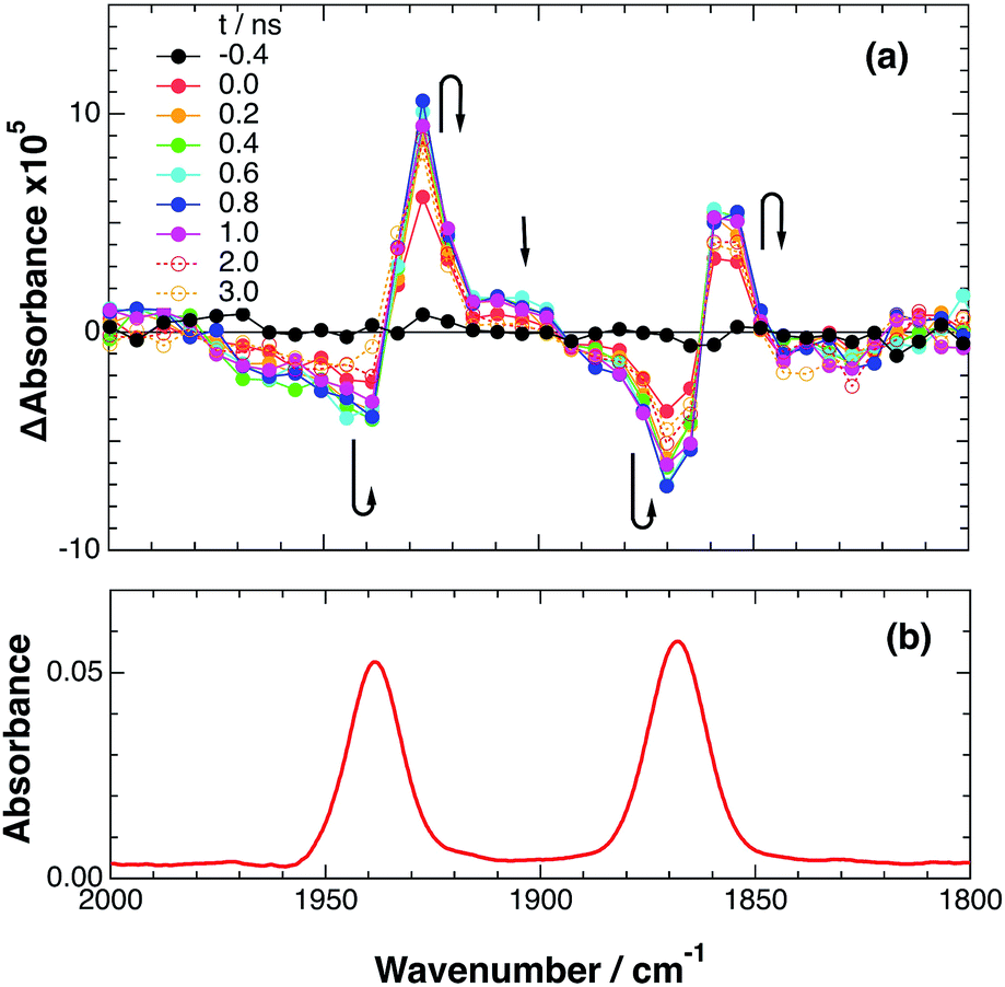

 ) in the ps-TRIR measurement of RuRe(FPh) in the presence of 0.3 M BIH in an argon-saturated DMF–TEOA (5