 Open Access Article
3D plum candy-like NiCoMnO4@graphene as anodes for high-performance lithium-ion batteries
Jianming Taoabc,
Guozhen Liuab,
Yuhan Chenab,
Yubin Chiab,
Lixun Hongab,
Zhiya Linab,
Yingbin Lin *abc and
Zhigao Huang
 abc
abc
aCollege of Physics and Energy, Fujian Normal University, Fujian Provincial Key Laboratory of Quantum Manipulation and New Energy Materials, Fuzhou, 350117, China. E-mail: yblin@fjnu.edu.cn; Fax: +86-591-2286-8132; Tel: +86-591-2286-8132
bFujian Provincial Engineering Technology Research Center of Solar Energy Conversion and Energy Storage, Fuzhou, 350117, China
cFujian Provincial Collaborative Innovation Center for Optoelectronic Semiconductors and Efficient Devices, Xiamen, 361005, China
First published on 19th December 2018
Abstract
3D plum candy-like NiCoMnO4 microspheres have been prepared via ultrasonic spraying and subsequently wrapped by graphene through electrostatic self-assembly. The as-prepared NiCoMnO4 powders show hollow structures and NiCoMnO4@graphene exhibits excellent electrochemical performances in terms of rate performance and cycling stability, achieving a high reversible capacity of 844.6 mA h g−1 at a current density of 2000 mA g−1. After 50 cycles at 1000 mA g−1, NiCoMnO4@graphene delivers a reversible capacity of 1045.1 mA h g−1 while the pristine NiCoMnO4 only has a capacity of 143.4 mA h g−1. The hierarchical porous structure helps to facilitate electron transfer and Li-ion kinetic diffusion by shortening the Li-ion diffusion length, accommodating the mechanical stress and volume change during the Li-ion insertion/extraction processes. Analysis from the electrochemical performances reveals that the enhanced performances could be also attributed to the reduced charge-transfer resistance and enhanced Li-ion diffusion kinetics because of the graphene-coating. Moreover, Schottky electric field, due to the difference in work function between graphene and NiCoMnO4, might be favorable for the redox activity of the NiCoMnO4. In light of the excellent electrochemical performance and simple preparation, we believe that 3D plum candy-like NiCoMnO4@graphene composites are expected to be applied as a promising anode materials for high-performance lithium ion batteries.
1. Introduction
In recent years, rechargeable lithium-ion batteries with high energy and power densities have attracted increasing interest due to their commercial application in portable electronic devices, electric vehicles and large-scale energy storage.1–3 Unfortunately, the commercial graphite anode with low theoretical specific capacity of 372 mA h g−1, could not satisfy the ever-growing demand for high energy-density lithium-ion batteries.4 Therefore, many strategies have been carried out to develop alternative anode materials with high energy, long cycling life and good rate capability as well.5,6 Among the explored systems, transition metal oxides have been reinvestigated as the most promising anode materials because of their high capacity, environmental friendliness, widespread availability and abundant oxidation states available for reversible redox reactions.7–10 In numerous transition metal oxides, spinel cobalt–nickel oxide (NiCo2O4) have received considerable attention owing to its high specific capacity (∼890 mA h g−1), environmental benignity and good electronic conductivity.11,12 However, NiCo2O4 suffers from large volume expansion/contraction, electrode pulverization and severe particle aggregation, resulting in loss of particle contact and poor cycling stability during the Li-ion insertion/extraction processes.13–15 Up to now, lots of effective strategies have been devoted to overcome these shortcomings, such as fabricating hierarchically structure, coupling with conducting substances and doping with isovalent ions.16–19 Chen et al.16 reported that TiO2-coating could improve electrochemical performances of flower-like NiCo2O4 nanosheets, resulting from enhanced structural stability, reduced charge-transfer resistance and improved Li-ion diffusion. Mo et al.17 reported that porous NiCo2O4@amorphous carbon delivered a high reversible capacity of 1224.8 mA h g−1 at a current density of 500 mA g−1.In this work, 3D plum candy-like NiCoMnO4@graphene composites have been successfully prepared based on ultrasonic spraying and electrostatic self-assembly method. The partial substitution of Co by Mn can effectively reduce the cost and toxicity of NiCo2O4 without sacrifice of specific capacity. In addition, plum candy-like and hollow structure obtained with a help of vacuum technique would shorten the Li-ion diffusion length, accommodate the mechanical stress–strain of the active materials during the electrochemical reaction. Moreover, the graphene-wrapping with NiCoMnO4 through electrostatic self-assembly could not only efficiently suppress electrode pulverization and particle aggregation, but also provide a high-conductive network for electron-transfer in the electrode. Owing to the hollow plum candy-like structure and high-conductive graphene network, the as-prepared NiCoMnO4@graphene as a novel anode material for lithium ion batteries exhibits an excellent electrochemical performances in term of rate capability and cycling stability.
2. Experimental section
2.1 Synthesis of NiCoMnO4 microspheres
NiCoMnO4 microspheres are prepared by ultrasonic spraying under the help of vacuum pump, shown in Fig. 1(a and b). Typically, 0.01 mol Ni(CH3COO)2·4H2O, 0.01 mol Co(CH3COO)2·4H2O and 0.01 mol Mn(CH3COO)2·4H2O are thoroughly dissolved in 100 mL deionized water, followed by continuous stirring until a pink solution is formed. Then, 0.2 g polyvinyl pyrrolidone (Mw = 58![[thin space (1/6-em)]](https://www.rsc.org/images/entities/char_2009.gif) 000) is added to the above aqueous solution under stirring. After vigorous stirring for another 30 min, the resulted solution is ultrasonically atomized and the droplets go through a reactor of 600 °C under the help of vacuum pump. The vacuum atmosphere in the reactor is favorable for the formation of the hollow structure. The Ni–Co–Mn–O precursors are collected and subsequently calcinated at 500 °C for 5 h in air to obtain NiCoMnO4 powders.
000) is added to the above aqueous solution under stirring. After vigorous stirring for another 30 min, the resulted solution is ultrasonically atomized and the droplets go through a reactor of 600 °C under the help of vacuum pump. The vacuum atmosphere in the reactor is favorable for the formation of the hollow structure. The Ni–Co–Mn–O precursors are collected and subsequently calcinated at 500 °C for 5 h in air to obtain NiCoMnO4 powders.
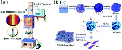 | ||
| Fig. 1 (a)Schematic diagram of the ultrasonic spraying process. (b) Schematic of the formation process of NiCoMnO4 and NiCoMnO4@graphene. | ||
2.2 Preparation of NiCoMnO4@graphene composites
NiCoMnO4@graphene composites are prepared by electrostatic interactions between positively charged NiCoMnO4 particles and negatively charged graphene oxide sheets in aqueous solution. Typically, 0.5 g of as-prepared NiCoMnO4 microspheres are dispersed in 50 mL of ethanol under ultrasonication for 30 min, followed by adding 5 mL of 3-aminopropyltriethoxysilane (APTES) under continuous stirring. After vigorous stirring for 5 h, the obtained precipitates are collected by centrifugation and washed with ethanol several times to get amino-silane modified NiCoMnO4 nanoparticles. Then, 0.12 g of amino-silane modified NiCoMnO4 powders are dispersed in 200 mL 0.4 mg mL−1 graphite oxide ethanol solution under vigorous sonication for 3 h, in which the positively-charged NiCoMnO4 nanoparticles are strongly adsorbed to the negatively-charged graphene-oxide via electrostatic interactions. Finally, the obtained precipitates are collected by centrifugation, washed with de-ionized water several times and consequently calcinated at 300 °C in an Ar atmosphere for 5 h to obtain the final product. The schematic illustration of the synthesis process for NiCoMnO4@graphene is shown in Fig. 1(b).2.3 Materials characterization
The crystalline structures of the as-prepared composites are characterized by X-ray diffraction (XRD, Rigaku MiniFlex II) using CuKα radiation (λ = 0.15405 nm). The surface morphologies of the NiCoMnO4 and NiCoMnO4@graphene are determined by a field-emission scanning electron microscopy (FESEM; HITACHI, SU-8010) equipped with an energy-dispersive spectroscopy (EDS). The microstructure of NiCoMnO4 is further examined by on a Tecnai G2 F20 S-Twin high resolution transmission electron microscopy. The chemical state and composition are analyzed using X-ray photoelectron spectroscopy (Thermo Scientific ESCALAB 250Xi). Nitrogen adsorption–desorption isotherms are measured at 77 K on a Micromeritics Tristar 3020 analyzer. The specific surface areas are calculated according to the Brunauer–Emmett–Teller method and the pore size distribution is determined based on Barrett Joyner and Halenda model. Thermogravimetric analysis (TGA) of NiCoMnO4@graphene are conducted on a Netzsch STA449F3 analyzer at a heating rate of 5 °C min−1 under an air flow.2.4 Electrochemical measurements
The electrochemical performances are evaluated by usingCR2025 coin-type cell. The working electrode is prepared by mixing the active material (NiCoMnO4 or NiCoMnO4@graphene), Super-P, and poly(vinylidene fluoride), with a weight ratio of 70![[thin space (1/6-em)]](https://www.rsc.org/images/entities/char_2009.gif) :
:![[thin space (1/6-em)]](https://www.rsc.org/images/entities/char_2009.gif) 20
20![[thin space (1/6-em)]](https://www.rsc.org/images/entities/char_2009.gif) :
:![[thin space (1/6-em)]](https://www.rsc.org/images/entities/char_2009.gif) 10 in N-methyl pyrrolidinone (NMP). The homogeneous slurry is cast onto copper current collector and subsequently dried at 120 °C in vacuum overnight. The obtained laminate is punched into a 12 mm diameter disc and the loading density of the active materials is 1.0–1.2 mg cm−2. Electrochemical cells are assembled in an Ar-filled glove box (O2 < 0.1 ppm, H2O < 0.1 ppm) using a Celgard 2400 microporous polypropylene membrane as the separator and lithium foil as the negative electrode. The electrolyte is a solution of 1 M LiPF6 in dimethyl carbonate (DMC)–ethylene carbonate (EC)–diethyl carbonate (DEC) (1
10 in N-methyl pyrrolidinone (NMP). The homogeneous slurry is cast onto copper current collector and subsequently dried at 120 °C in vacuum overnight. The obtained laminate is punched into a 12 mm diameter disc and the loading density of the active materials is 1.0–1.2 mg cm−2. Electrochemical cells are assembled in an Ar-filled glove box (O2 < 0.1 ppm, H2O < 0.1 ppm) using a Celgard 2400 microporous polypropylene membrane as the separator and lithium foil as the negative electrode. The electrolyte is a solution of 1 M LiPF6 in dimethyl carbonate (DMC)–ethylene carbonate (EC)–diethyl carbonate (DEC) (1![[thin space (1/6-em)]](https://www.rsc.org/images/entities/char_2009.gif) :
:![[thin space (1/6-em)]](https://www.rsc.org/images/entities/char_2009.gif) 1
1![[thin space (1/6-em)]](https://www.rsc.org/images/entities/char_2009.gif) :
:![[thin space (1/6-em)]](https://www.rsc.org/images/entities/char_2009.gif) 1 in volume). The galvanostatic charge/discharge measurements are carried out on a LAND test system (LAND CT2001A) in a voltage range from 0.01 to 3.0 V. Cyclic voltammogram (CV) and electrochemical impedance spectra (EIS) measurements of the cells are performed on a Zahner Zennium IM6 electrochemical workstation.
1 in volume). The galvanostatic charge/discharge measurements are carried out on a LAND test system (LAND CT2001A) in a voltage range from 0.01 to 3.0 V. Cyclic voltammogram (CV) and electrochemical impedance spectra (EIS) measurements of the cells are performed on a Zahner Zennium IM6 electrochemical workstation.
3. Results and discussion
3.1 Morphological and physical characterization
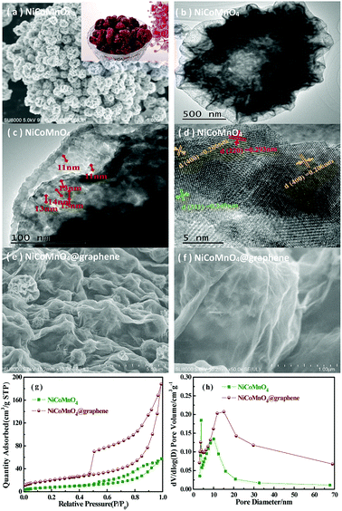
Fig. 2(a) shows the typical SEM images of the as-prepared NiCoMnO4 powders. As can be seen, the morphologies of the as-synthesized NiCoMnO4 powders are shriveled microspherical in shape with uniform size of 500–1500 nm, which demonstrate three-dimensional plum candy-like structures. The contrast between the dark edge and the gray center of microsphere shown in Fig. 2(b), revealing the hollow nature of the as-prepared NiCoMnO4 powders. Fig. 2(c) reveals that plum candy-like NiCoMnO4 particle consists of numerous tiny well-crystalline particles with an average particle-size of ∼13 nm. Analysis from high-resolution TEM images (Fig. 2(d)) reveals that the distinct lattice fringes with average distance of 0.293, 0.249 and 0.206 nm correspond to the (220), (311) and (400) planes of spinel NiCoMnO4, respectively. Such hierarchical structure would provide plenty of channels for electrolyte permeation and shorten Li-ion diffusion length. The SEM images of NiCoMnO4@graphene powders shown in Fig. 2(e and f), show that NiCoMnO4 particles are wrapped by gauze-like graphene nanosheets and the isolated NiCoMnO4 particles are connected by wrinkled graphene sheets, which provides a high-conductive network for electron-transfer in composites. Fig. 2(g) shows N2 adsorption/desorption isotherms of the NiCoMnO4 and NiCoMnO4@graphene. Both samples exhibit typical type-IV isotherm curves with obvious hysteresis loops, suggesting a typical characteristic of mesoporous structure for the as-prepared samples.17,20 Based on Brunauer–Emmett–Teller (BET) theory, the specific surface areas of NiCoMnO4 and NiCoMnO4@graphene are calculated to be 28.01 and 71.60 m2 g−1, respectively. Fig. 2(h) shows Barrett–Joyner–Halenda (BJH) pore-size distribution of NiCoMnO4 and NiCoMnO4@graphene, indicating that NiCoMnO4@graphene has larger average pore size (16.19 nm) than that (12.59 nm) of the pristine one.The XPS measurements are performed to investigate the chemical state of NiCoMnO4@graphene powders. The survey spectrum (Fig. 3(a)) obviously shows the presence of Ni, Co, Mn, O and C elements in the NiCoMnO4@graphene powders. All XPS signals are fitted with mixed Lorentzian–Gaussian curves. Fig. 3(b) shows that the Ni 2p core-level spectrum has two spin–orbit doublets around 855.1 and 872.8 eV respectively accompanied by two shake-up satellites, which are consistent with the characteristic of Ni2+ and Ni3+.21 Two fitted peaks are observed at 780.6 and 796.0 eV shown in Fig. 3(c) are assigned to Co 2p3/2 and Co 2p1/2 spin–orbit doublets, revealing the presence of Co2+ and Co3+. Fig. 3(d) presents the Mn 2p core-level spectrum, confirming the existence of Mn2+ and Mn3+ in composites. Based on the peak area of Ni-2p, Co-2p, Mn-2p, the atomic ratio of Ni, Co and Mn is about 1.03![[thin space (1/6-em)]](https://www.rsc.org/images/entities/char_2009.gif) :
:![[thin space (1/6-em)]](https://www.rsc.org/images/entities/char_2009.gif) 0.96
0.96![[thin space (1/6-em)]](https://www.rsc.org/images/entities/char_2009.gif) :
:![[thin space (1/6-em)]](https://www.rsc.org/images/entities/char_2009.gif) 1. The high-resolution O 1s spectrum (Fig. 2(e)) can be divided into three oxygen contributions. The fitting peak located at 529.9 eV is typical of metal–oxygen bonds.22 The fitting peak located at 531.6 eV is typically related with defects, and under-coordinated lattice oxygen.23 The fitting peak around 533.0 eV is attributed to surface-absorbed oxygen at or near the surface.24 The high-resolution C 1s spectrum (Fig. 2(f)) reveals many functional groups such as C–C/C–C (284.9 eV), C–OH (286.2 eV) and C–O (288.7 eV) on the graphene sheets, which are greatly association with NiCoMnO4 by covalent chemical bond, hydrogen bonding or van der Waal's forces, and favor direct growth of NiCoMnO4 on rGO sheets.25 The mixed-valence nature of the NiCoMnO4 composites could be beneficial in energy storage applications.
1. The high-resolution O 1s spectrum (Fig. 2(e)) can be divided into three oxygen contributions. The fitting peak located at 529.9 eV is typical of metal–oxygen bonds.22 The fitting peak located at 531.6 eV is typically related with defects, and under-coordinated lattice oxygen.23 The fitting peak around 533.0 eV is attributed to surface-absorbed oxygen at or near the surface.24 The high-resolution C 1s spectrum (Fig. 2(f)) reveals many functional groups such as C–C/C–C (284.9 eV), C–OH (286.2 eV) and C–O (288.7 eV) on the graphene sheets, which are greatly association with NiCoMnO4 by covalent chemical bond, hydrogen bonding or van der Waal's forces, and favor direct growth of NiCoMnO4 on rGO sheets.25 The mixed-valence nature of the NiCoMnO4 composites could be beneficial in energy storage applications.
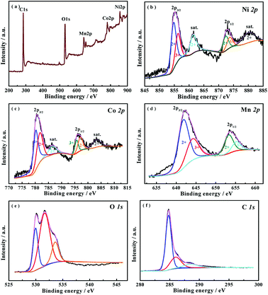 | ||
| Fig. 3 XPS spectra of (a) survey spectrum, (b) Ni 2p, (c) Co 2p, (d) Mn 2p and (e) O 1s (f) C 1s for the NiCoMnO4@graphene powders. | ||
Fig. 4(a) shows the XRD diffraction patterns of the as-prepared NiCoMnO4 and NiCoMnO4@graphene composites. All of the diffraction peaks of NiCoMnO4 are well indexed to spinel NiCo2O4 (JCPDS card no. 20-0781).26 No impurity phases are found in XRD patterns, indicating the substitution of Co by Mn could not change NiCo2O4 spinel structure. Besides the diffraction peaks of NiCoMnO4, two additional small and broad diffraction peak around at 25° can be assigned to the disorderedly stacked graphene sheets.27 No peak-shifting is observed between NiCoMnO4 and NiCoMnO4@graphene, suggesting graphene-wrapping does not change the crystal structure of NiCoMnO4 during the calcination process. Thermogravimetric analysis (Fig. 4(b)) reveals that the mass content of graphene in composite is about 37.5 wt% in NiCoMnO4@graphene composites.
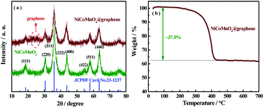 | ||
| Fig. 4 (a) XRD patterns of NiCoMnO4 and NiCoMnO4@graphene powders. (b) TGA curves of the NiCoMnO4@graphene in air atmosphere. | ||
3.2 Electrochemical measurements
Fig. 5 shows the rate performances of NiCoMnO4 and NiCoMnO4@graphene electrodes between 0.01–3 V at various current rates. Comparing to the pristine NiCoMnO4, NiCoMnO4@graphene delivers higher capacities especially at higher current density. As the current density increases, NiCoMnO4@graphene electrodes have reversible discharge capacities of 1014.1, 975.9, 928.4, 915.4, 914.3 and 844.6 mA h g−1 respectively. Interestingly, when the current density reverses back to 100 mA g−1, the discharge capacities of NiCoMnO4@graphene recovered to the higher values (1183.8 mA h g−1) than previous cycles. The increasing capacity with increasing cycles might be attributed to the electrochemical activation of active materials and the improvement of electrolyte infiltration. Such superior rate capability indicates that NiCoMnO4@graphene has potential application in high-power-density lithium-ion batteries. On the contrary, the pure NiCoMnO4 electrode displays a fast capacity fading along with the cycling, only retaining a discharge capacity of 33 mA h g−1 at 2000 mA g−1. The significant improvement in rate capability of NiCoMnO4@graphene should be attributed to the formation of high-conductive graphene networks in electrode, which facilitates the charge transfer and consequently reduces the polarization of the electrode. On the other hand, graphene-wrapping could also effectively suppress aggregation of NiCoMnO4 particle, reduce interfacial resistance among NiCoMnO4 particles, and facilitate electron transfer in composites.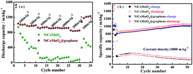 | ||
| Fig. 5 (a) Rate capability and (b) cycling performances of NiCoMnO4 and NiCoMnO4@graphene electrodes. | ||
Fig. 5(b) shows the cycling behavior of NiCoMnO4 and NiCoMnO4@graphene electrodes at a current density of 1000 mA g−1 in 0.01–3.0 V. It is clear that NiCoMnO4@graphene delivers a higher discharge capacity and exhibits excellent cycling stability. After 50 cycles, NiCoMnO4@graphene electrode delivers a reversible capacity of 1045.1 mA h g−1 while NiCoMnO4 electrode is merely 143.4 mA h g−1. The continuous increase in capacity of NiCoMnO4@graphene during the initial 50 cycles might be associated with two phenomena: (a) a gradual activation of graphene during conversion process, and (b) the improvement of electrolyte infiltration. The comparison summarized in Table 1 indicates that NiCoMnO4@graphene with excellent performances could be a promising candidate for high-energy lithium-ion batteries.
| Materials | Current density (mA g−1) | Capacity (mA h g−1) | Reference |
|---|---|---|---|
| NiCoMnO4@graphene | 1000 | 1045 after 50 cycles | This work |
| Carbon coated Ni–Co–Mn–O | 450 | 395 after 50 cycles | 28 |
| Ni–Co–Mn oxide TS-HS | 1000 | 700 after 200 cycles | 21 |
| Mn0.4Ni0.6Co2O4 nanowires | 100 | 786 after 175 cycles | 29 |
| NiCo2O4/G nanosheet | 300 | 806 after 55 cycles | 13 |
| NiCo2O4@graphene | 200 | 994 after 50 cycles | 18 |
| NiO–MnCo2O4 | 200 | 846 after 50 cycles | 30 |
| NiCo2O4@GO | 100 | 789.9 after 100 cycles | 31 |
| Co3O4@graphene | 1000 | 967 after 100 cycles | 32 |
| Co3O4/graphene | 1000 | 827 after 50 cycles | 33 |
A series of electrochemical measurements are performed to investigate the effect of graphene-wrapping on Li-ion kinetic behaviors in composites. Fig. 6(a) and (b) shows the cyclic voltammograms of the first six cycles for NiCoMnO4 and NiCoMnO4@graphene electrode in the voltage range of 0.01–3 V vs. Li/Li+ at a scan rate of 0.2 mV s−1, respectively. A distinct peak is observed around 0.56 V in the initial cathodic scanning for NiCoMnO4 sample, which is assigned to the reduction of NiCoMnO4 to Ni, Co and Mn and the formation of a solid electrolyte interface (SEI) layer.28 In the anodic process, two broad oxidation peaks are found at 1.59 and 1.97 V, corresponding to the oxidation of Mn0 to Mn2+, Ni0 to Ni2+ and Co0 to Co2+, respectively.28,34 Based on the above CV analysis and other's reports,28,34 the lithium insertion/extraction reactions for plum candy-like NiCoMnO4 anodes are believed to be processed as follows:
| NiCoMnO4 + 8Li+ + 8e− → Ni + Co + Mn + 4Li2O | (1) |
| Ni + Co + Mn + 4Li2O ↔ NiO + CoO + MnO + 6Li+ + 6e− | (2) |
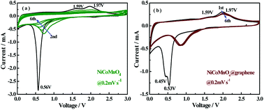 | ||
| Fig. 6 CV curves of the (a) NiCoMnO4 and (b) NiCoMnO4@graphene electrodes at a scanning rate of 0.2 mV s−1. | ||
NiCoMnO4@graphene electrode exhibits similar cathodic and anodic behaviors. In the following cycle, the cathodic peak gradually shifts to higher voltage range and becomes much broader, while the anodic peak keeps almost the same as the first cycle. From the second cycle onward, the CV curves overlap of NiCoMnO4@graphene electrode is found to be better than that of NiCoMnO4 electrode, suggesting that the graphene-coating helps to enhance lithiation/delithiation reversibility and cycle stability.18,35
To investigate the potential mechanism behind the improved performances of NiCoMnO4@graphene, electrochemical impedance spectra (EIS) of NiCoMnO4 and NiCoMnO4@graphene electrodes after 15, 30, 50 cycles at 1000 mA g−1 in the fully discharged state, are carried out, shown Fig. 7(a and b). All EIS curves are fitted with the equivalent circuits shown in Fig. 7(c), where Rs is the solution resistance, RSEI stands for the resistance of the SEI film, Rct was the charge transfer resistance at the particle/electrolyte interface. According to the equivalent circuit, the values of Rct for the NiCoMnO4 electrodes are calculated to be 110.0, 520.7 and 3010.0 Ω respectively, while the Rct of NiCoMnO4@graphene electrodes are only 10.0, 10.9 and 13.4 Ω. High-conductivity graphene network among NiCoMnO4 particles should be responsible for the reduction in Rct.36 Moreover, it is expected that graphene-wrapping acting as a cage-like framework around NiCoMnO4, efficiently suppresses aggregation of NiCoMnO4 particle due to volume expansion and facilitates electron transfer in the electrode.37
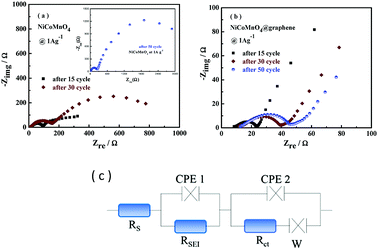 | ||
| Fig. 7 (a) Electrochemical impedance spectroscopies of (a) NiCoMnO4 and (b) NiCoMnO4@graphene at the full discharged state after 15, 30, 50 cycles. (c) The equivalent circuit for EIS fitting. | ||
Fig. 8 shows the morphologies of NiCoMnO4 and NiCoMnO4@graphene particles after 15 cycles at 1000 mA g−1, respectively. Fig. 8(b) shows that NiCoMnO4 particles has serious structure-deterioration and losses its plum candy-like morphologies, which would not only increase interfacial resistance among particles but also reduce the contact areas of active materials with the electrolyte. Fig. 8(c) reveals that NiCoMnO4@graphene electrode has less aggregation than that (Fig. 8(a)) of the bare one, and unambiguously confirms the graphene-network in the electrode. In contrast, as shown in Fig. 8(d), NiCoMnO4@graphene powders can maintain the plum candy-like structure well, further confirming that graphene-wrapping indeed efficiently withstands the structural strain in NiCoMnO4, enhance the structure stability during the electrochemical cycling, and consequently offer more active sites for Li-ion insertion/extraction. As a result, the electrochemical performances are enhanced.
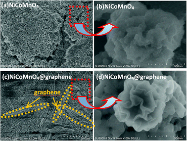 | ||
| Fig. 8 FE-SEM images of (a and b) NiCoMnO4 and (c and d) NiCoMnO4@graphene after 15 cycles of 1000 mA g−1, respectively. | ||
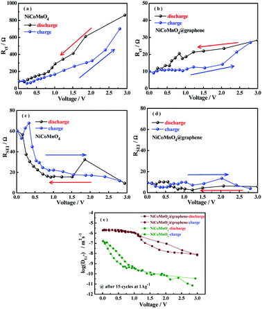
To further study the effect of graphene-wrapping on the Li-ion diffusion kinetics of NiCoMnO4, the electrochemical impedance spectra under different charge/discharge states after 15 cycles for NiCoMnO4 and NiCoMnO4@graphene electrodes are continuously measured during the lithium-ion insertion/extraction process. The cells are charged/discharged at 100 mA g−1 and the electrochemical impedance spectra are recorded for every 10 min. The EIS spectra (Z′′ vs. Z′) of NiCoMnO4 and NiCoMnO4@graphene electrodes are shown in Fig. 9. According to the equivalent circuit shown in Fig. 7(c), the charge transfer resistances (Rct) are calculated and the dependences of Rct on operation voltage for NiCoMnO4 and NiCoMnO4@graphene electrodes are given in Fig. 10(a and b). During the lithiation process, Rct is found to decreases monotonously due to the formation of the SEI layer.38 On the other hand, the cracked SEI layer induced by volume expansion of active materials would enlarge contact area between active material and electrolyte, leading to the decrease of the charge transfer resistance.39 During the delithiation process, Rct monotonously up to 695.0 Ω because of the restructuring of the SEI layer. In comparison, NiCoMnO4@graphene electrodes show lower charge transfer resistances on a whole, suggesting that graphene-wrapping would favor charge transfer and structure stability of NiCoMnO4 material during the charging/discharging process. Fig. 10(c and d) shows the SEI film resistance (RSEI) as function of the cell voltage for NiCoMnO4 and NiCoMnO4@graphene electrodes. For NiCoMnO4 shown in Fig. 10(c), RSEI increases from 9.36 Ω to 32.3 Ω with decreasing of the cell voltage as a result of the electrolyte degradation.40 During the lithiation process, the sharp increase of the RSEI at the low voltage indicates the growth in thickness of the SEI as the potential becomes more negative.41 During the de-alloying process, RSEI decreases reversibly to the original level. Such change in RSEI would be strongly related to the expansion and extraction of NiCoMnO4 volume. Similar behaviors have been reported.41,42 In contrast, NiCoMnO4@graphene exhibits negligible change in RSEI during the lithiation and delithiation process, indicating graphene-wrapping is helpful to the formation of stable SEI film.
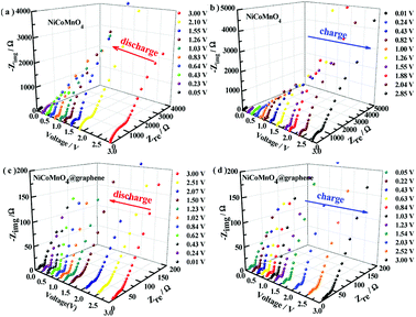 | ||
| Fig. 9 The impedance spectra of NiCoMnO4 and NiCoMnO4@graphene electrodes under different charge/discharge states after 15 cycles of 1000 mA g−1. | ||
The Li-ion diffusion coefficient of (DLi+) could be evaluated according to the linear relationship between the real axis (Zre) and the reciprocal square root (ω−1/2) in the low frequency region34
| Zre = Rs + Rct + σwω−1/2 | (3) |
 | (4) |
Work function is defined with respected to the Fermi energy of the electrons, reflecting the minimum kinetic energy of the electrons to overcome the barrier and escape the composite. Fig. 11(a–c) presents the surface potential images of Au foil, NiCoMnO4 and NiCoMnO4@graphdiyne composites, determined by Kelvin probe atomic force microscopy. Here, Au foil is served as calibration sample whose work function (ΦAu) is 5.31 eV. According to our previous work,16 the work functions of NiCoMnO4 and NiCoMnO4@graphdiyne are evaluated, shown in Fig. 11(d). It is found that NiCoMnO4@graphdiyne has a smaller work function (5.10 eV) than that (5.20 eV) of NiCoMnO4. Smaller work function reflects less energy for electrons to escape from NiCoMnO4@graphdiyne, resulting from the high-conductive graphene network in composite. As a result, the electrochemical performances are correspondingly enhanced.
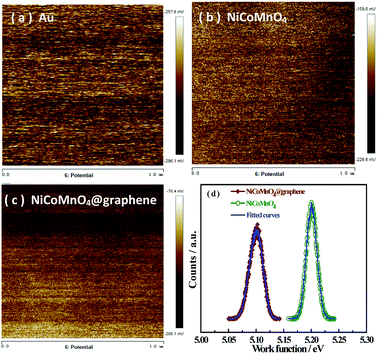 | ||
| Fig. 11 Surface potential maps of (a)Au foil, (b) NiCoMnO4 and (c) NiCoMnO4@graphene powders; (d) work functions of NiCoMnO4 and NiCoMnO4@graphene composites. | ||
The energy-band model is employed to explain the reduction in work function of the composite because of the graphene-wrapping. Due to their different work functions, the free electrons would transfer from graphene with low work function to the NiCoMnO4 with high work function at the interface between graphene and NiCoMnO4 until the Fermi levels are aligned. Under equilibrium, the graphene is positively charged while the NiCoMnO4 is negatively charged at the interface, and a Schottky electric field is consequently established.43 Due to the low carrier-density concentration in the NiCoMnO4 semiconductor, Schottky electric field could not be effectively screened and the free electrons tend to accumulate near the NiCoMnO4 surface, which might be favorable for the redox activity of the NiCoMnO4.44 As a result, the electrochemical performances of NiCoMnO4@graphene are significantly improved.
4. Conclusions
3D plum candy-like NiCoMnO4 microspheres have been prepared by ultrasonic spraying with the help of vacuum and subsequently wrapped by graphene through electrostatic self-assembly. NiCoMnO4@graphene delivers a high reversible capacity of 844.6 mA h g−1 at a current density of 2000 mA g−1 and 1045.1 mA h g−1 at 1000 mA g−1 after 50 cycles. Such hierarchical porous structure helps to facilitate electron transfer, Li-ion kinetic diffusion in composites and accommodating the mechanical stress. In addition, high-conductive graphene network could reduce the charge-transfer resistance and enhance structural stability of NiCoMnO4 materials, resulting in the significant improvement in the electrochemical performances. Moreover, Schottky electric field due to the difference in work function between graphene and NiCoMnO4 might be favorable for the redox activity of the NiCoMnO4.Conflicts of interest
There are no conflicts to declare.Acknowledgements
This work was supported by the Key Project of Department of Science & Technology of Fujian Province (No. 2014H0020) and Solar Energy Conversion & Energy Storage Engineering Technology Innovation Platform (No. 2018L3006).References
- J. B. Goodenough, Energy Environ. Sci., 2014, 7, 14 RSC.
- Z. P. Cano, D. Banham, S. Ye, A. Hintennach, J. Lu, M. Fowler and Z. Chen, Nat. Energy, 2018, 3, 279 CrossRef.
- M. Li, J. Lu, Z. Chen and K. Amine, Adv. Mater., 2018, 30, 1 Search PubMed.
- N. Nitta, F. Wu, J. T. Lee and G. Yushin, Mater. Today, 2015, 18, 252 CrossRef CAS.
- S. J. Lee, H. J. Kim, T. H. Hwang, S. Choi, S. H. Park, E. Deniz, D. S. Jung and J. W. Choi, Nano Lett., 2017, 17, 1870 CrossRef CAS PubMed.
- K. Zhou, L. Lai, Y. Zhen, Z. Hong, J. Guo and Z. Huang, Chem. Eng. J., 2017, 316, 137 CrossRef CAS.
- M. V. Reddy, G. V. Subba Rao and B. V. R. Chowdari, Chem. Rev., 2013, 113, 5364 CrossRef CAS.
- Y. Zhao, X. Li, B. Yan, D. Xiong, D. Li, S. Lawes and X. L. Sun, Adv. Energy Mater., 2016, 6, 1 Search PubMed.
- T. Jiang, F. Bu, X. Feng, I. Shakir, G. Hao and Y. Xu, ACS Nano, 2017, 11, 5140 CrossRef CAS PubMed.
- M. Zheng, H. Tang, L. Li, Q. Hu, L. Zhang, H. Xue and H. Pang, Adv. Sci., 2018, 5, 1700592 CrossRef PubMed.
- F. Fu, J. Li, Y. Yao, X. Qin, Y. Dou, H. Wang, J. Tsui, K. Y. Chan and M. Shao, ACS Appl. Mater. Interfaces, 2017, 9, 16194 CrossRef CAS PubMed.
- Y. Wang, P. Liu, K. Zhu, J. Wang, K. Yan and J. Liu, Electrochim. Acta, 2018, 273, 1 CrossRef CAS.
- Y. Chen, J. Zhu, B. Qu, B. Lu and Z. Xu, Nano Energy, 2014, 3, 88 CrossRef CAS.
- J. Xu, D. Su, W. Bao, Y. Zhao, X. Xie and G. Wang, J. Alloys Compd., 2016, 684, 691 CrossRef CAS.
- C. Ding, L. Wang, W. Zhou, D. Wang, Y. Du and G. Wen, Chem. Eng. J., 2018, 353, 340 CrossRef CAS.
- W. Chen, L. Y. Wei, Z. Y. Lin, Q. Liu, Y. Chen, Y. B. Lin and Z. G. Huang, RSC Adv., 2017, 7, 47602 RSC.
- Y. Mo, Q. Ru, X. Song, L. Guo, J. Chen, X. Hou and S. Hu, Carbon, 2016, 109, 616 CrossRef CAS.
- J. Yang, H. Tian, J. Tang, T. Bai, L. Xi, S. Chen and X. Zhou, Appl. Surf. Sci., 2017, 426, 1055 CrossRef CAS.
- Y. Duan, Y. Huo, Y. Qi, L. Li, Q. Wu, C. Wang and Z. Su, J. Alloys Compd., 2018, 767, 223 CrossRef CAS.
- M. Thommes, K. Kaneko, A. V. Neimark, J. P. Olivier, F. Rodriguez-Reinoso, J. Rouquerol and K. S. W. Sing, Pure Appl. Chem., 2015, 87, 1051 CAS.
- D. Luo, Y. P. Deng, X. Wang, G. Li, J. Wu, J. Fu, W. Lei, R. Liang, Y. Liu, Y. Ding, A. Yu and Z. Chen, ACS Nano, 2017, 11, 11521 CrossRef CAS.
- J. F. Marco, J. R. Gancedo, M. Gracia, J. L. Gautier, E. Ríos and F. J. Berry, J. Solid State Chem., 2000, 153, 74 CrossRef CAS.
- R. Ding, L. Qi, M. Jia and H. Wang, J. Power Sources, 2014, 251, 287 CrossRef CAS.
- Y. Mo, Q. Ru, X. Song, S. Hu, L. Guo and X. Chen, Electrochim. Acta, 2015, 176, 575 CrossRef CAS.
- E. Umeshbabu and G. Ranga Rao, Electrochim. Acta, 2016, 213, 717 CrossRef CAS.
- M. Liu, L. Wang, Y. Mu, J. Ma, Y. Zhao, Y. Wang, X. Lai, J. Bi and D. Gao, Scr. Mater., 2018, 146, 13 CrossRef CAS.
- Z. Wu, W. Ren, L. Wen, L. Gao, J. Zhao, Z. Chen, G. Zhou, F. Li and H. Cheng, ACS Nano, 2010, 4, 3187 CrossRef CAS.
- D. McNulty, H. Geaney and C. O. Dwyer, Sci. Rep., 2017, 7, 1 CrossRef.
- A. F. Shaikh, R. S. Kalubarme, M. S. Tamboli, S. S. Patil, M. V. Kulkarni, D. R. Patil, S. W. Gosavi, C. J. Park and B. B. Kale, ChemistrySelect, 2017, 2, 4630 CrossRef CAS.
- T. Li, X. Li, Z. Wang, H. Guo, Q. Hu and W. Peng, Electrochim. Acta, 2016, 191, 392 CrossRef CAS.
- H. Rong, Y. Qin, Z. Jiang, Z. J. Jiang and M. Liu, J. Alloys Compd., 2018, 731, 1095 CrossRef CAS.
- R. Hu, H. Zhang, Y. Bu, H. Zhang, B. Zhao and C. Yang, Electrochim. Acta, 2017, 228, 241 CrossRef CAS.
- Y. Yang, J. Huang, J. Zeng, J. Xiong and J. Zhao, ACS Appl. Mater. Interfaces, 2017, 9, 32801 CrossRef CAS PubMed.
- L. Wu, J. Lang, S. Wang, P. Zhang and X. Yan, Electrochim. Acta, 2016, 203, 128 CrossRef CAS.
- X. Hu, G. Zeng, J. Chen, C. Lu and Z. Wen, J. Mater. Chem. A, 2017, 5, 4535 RSC.
- Z. Li, L. Zhang, X. Ge, C. Li, S. Dong, C. Wang and L. Yin, Nano Energy, 2017, 32, 494 CrossRef CAS.
- Y. Gu, Z. Jiao, M. Wu, B. Luo, Y. Lei, Y. Wang, L. Wang and H. Zhang, Nano Res., 2017, 10, 121 CrossRef CAS.
- Y. Xia, Z. Xiao, X. Dou, H. Huang, X. Lu, R. Yan, Y. Gan, W. Zhu, J. Tu, W. Zhang and X. Tao, ACS Nano, 2013, 7, 7083 CrossRef CAS PubMed.
- A. T. Tesfaye, Y. D. Yücel, M. K. S. Barr, L. Santinacci, F. Vacandio, F. Dumur, S. Maria, L. Monconduit and T. Djenizian, Electrochim. Acta, 2017, 256, 155 CrossRef CAS.
- A. Mahmoud, M. Chamas and P. E. Lippens, Electrochim. Acta, 2015, 184, 387 CrossRef CAS.
- Y. M. Lee, J. Y. Lee, H. T. Shim, J. K. Lee and J. K. Park, J. Electrochem. Soc., 2017, 154, A515 CrossRef.
- S. Zhang, M. S. Ding, K. Xu, J. Allen and T. R. Jow, Electrochem. Solid-State Lett., 2001, 4, A206 CrossRef CAS.
- J. Qi, H. Zhang, D. Ji, X. Fan, L. Cheng, H. Liang, H. Li, C. Zeng and Z. Zhang, Adv. Mater., 2014, 26, 3735 CrossRef CAS.
- C. Zhang, X. P. Geng, S. L. Tang, M. S. Deng and Y. W. Du, J. Mater. Chem. A, 2017, 5, 5912 RSC.
| This journal is © The Royal Society of Chemistry 2018 |

