
 Open Access Article
 This Open Access Article is licensed under a Creative Commons Attribution-Non Commercial 3.0 Unported Licence
Broadband ultraviolet to near infrared conversion in Eu2+,Nd3+ co-doped SrAl2O4
Yuping Tai a,
Bingli Pan*a,
Xinzhong Lib,
Zhaogang Niec,
Xigang Dua and
Guanghui Yuand
a,
Bingli Pan*a,
Xinzhong Lib,
Zhaogang Niec,
Xigang Dua and
Guanghui Yuand
aSchool of Chemical Engineering and Pharmaceutics, Henan University of Science and Technology, Luoyang, 471003, P. R. China. E-mail: blpan@haust.edu.cn
bSchool of Physics and Engineering, Henan University of Science and Technology, Luoyang, 471003, P. R. China
cSchool of Physics and Optoelectronic Engineering, Guangdong University of Technology, Guangzhou 510006, P. R. China
dDepartment of Chemistry and Chemical Engineering, Ankang University, Ankang 725000, P. R. China
First published on 7th November 2018
Abstract
In this study, we investigated the quantum cutting (QC) mechanism in Eu2+–Nd3-co-doped SrAl2O4 microcrystals by fluorescence spectroscopy and decay lifetime analysis. In this material, the near-infrared (NIR) emissions of Nd3+ in the range of 800–1200 nm were enhanced under the excitation of the Eu2+:4f7 → 4f65d1 transition radiation. The lifetime of the 5d1 level of Eu2+ decreased with the increase in the Nd3+ concentration. These results verified the occurrence of cooperative energy transfer (CET) from the Eu2+:5d1 excited state to the Nd3+:4F3/2 level, by which one absorbed ultraviolet-visible photon was converted to two NIR photons with an optimal quantum efficiency (QE) of approximately 177.1%. Therefore, this broadband QC material paves the way for a further increase in the conversion efficiency of c-Si solar cells.
1. Introduction
With the rapid development of the global economy and industry the traditional energy resources face the problems of exhaustion and serious environmental pollution. Solar energy is a representative alternative clean energy with significant advantages: it is abundant, non-pollution, and inexhaustible. The solar energy supplied from the sun is approximately 10![[thin space (1/6-em)]](https://www.rsc.org/images/entities/char_2009.gif) 000 times higher than the current energy consumption on the Earth.1 Therefore, it becomes the most promising energy resource of interest to national governments. Since its development in the previous century, the silicon solar cell has been extensively employed in various industries owing to its low cost, optimized preparation technology, and high efficiency.2–4 However, silicon has a band-gap of 1.12 eV and thus it can only absorb near-infrared (NIR) photons in the solar spectrum range of 900–1200 nm; the majority of the energy in the ultraviolet-visible (UV-Vis) region is lost owing to thermalization of charge carriers, referred to as spectral mismatch, which significantly restricts the conversion efficiency of the c-Si solar cell to 19%. The efficiency is significantly lower than the theoretical value of 31.0% reported by Shockley.5 Extensive studies have been performed to decrease the energy loss caused by spectral mismatch and to increase the device efficiency.6–10 However, most methods have disadvantages of high costs and complex preparation processes, which limit their applications in solar cells. Quantum cutting (QC) is a promising method to increase the efficiencies of solar cells. According to the design of a luminescent layer on top of the solar cell, one incident UV-Vis photon was converted to two NIR photons, efficiently absorbed by the c-Si solar cell. Therefore, the energy loss caused by thermalization could be effectively suppressed and thus the efficiency of the solar cell could be increased.11,12
000 times higher than the current energy consumption on the Earth.1 Therefore, it becomes the most promising energy resource of interest to national governments. Since its development in the previous century, the silicon solar cell has been extensively employed in various industries owing to its low cost, optimized preparation technology, and high efficiency.2–4 However, silicon has a band-gap of 1.12 eV and thus it can only absorb near-infrared (NIR) photons in the solar spectrum range of 900–1200 nm; the majority of the energy in the ultraviolet-visible (UV-Vis) region is lost owing to thermalization of charge carriers, referred to as spectral mismatch, which significantly restricts the conversion efficiency of the c-Si solar cell to 19%. The efficiency is significantly lower than the theoretical value of 31.0% reported by Shockley.5 Extensive studies have been performed to decrease the energy loss caused by spectral mismatch and to increase the device efficiency.6–10 However, most methods have disadvantages of high costs and complex preparation processes, which limit their applications in solar cells. Quantum cutting (QC) is a promising method to increase the efficiencies of solar cells. According to the design of a luminescent layer on top of the solar cell, one incident UV-Vis photon was converted to two NIR photons, efficiently absorbed by the c-Si solar cell. Therefore, the energy loss caused by thermalization could be effectively suppressed and thus the efficiency of the solar cell could be increased.11,12
Rare-earth (RE) ions are optimal candidates for QC owing to their abundant energy levels. Considering the energy levels of lanthanides, the Yb3+ ion has a single excited state at approximately 10000 cm−1 and exclusively emits NIR photons at ∼1000 nm, which correspond to the strongest spectral response of c-Si. Therefore, many studies have been focused on the RE–Yb3+ co-doped system (RE = Eu2+,13,14 Ce3+,15–17 Pr3+,18–20 Er3+,21,22 and Tb3+ (ref. 23 and 24)) in recent years. The RE ion absorbs one incident UV-Vis photon and transfer its energy to two Yb3+ ions by cooperative energy transfer (CET) with an optimal QE of approximately 200%.25,26 However, the NIR luminescent intensity of the Yb3+ ion is significantly lower than that of its counterpart in the UV-Vis region. In addition, charge transfer state (CTS) could emerge for Yb2+–O2− or Yb3+–O2−.13,16 These disadvantages have decreased the practical QE for the RE–Yb3+ couple and further limited its application to solar cells.
Nd3+ is an another RE ion with NIR luminescence in the range of 800–1500 nm. The Nd3+ fluorescence intensity at NIR wavelengths is higher than that of Yb3+; in addition, no CTS emerges during the ET process. The NIR luminescence of Nd3+ is in the wavelength range of 800–1500 nm, significantly broader than that of Yb3+ of 900–1100 nm; and the spectral response range to c-Si could be broadened. Therefore, the RE–Nd3+ couples have larger potentials to increase the efficiency of c-Si. However, only a limited number of studies analyzed the RE–Nd3+ co-doped system and its QC property.27,28 The Eu2+ ion is a typical broadband sensitizer owing to the allowed 4f → 5d transition; its fluorescence spectra have been controlled by the crystal field of the matrix. The emission spectrum of the Eu2+ ion in a SrAl2O4 matrix well overlaps with the Nd3+ excitation spectrum. The energy of the Eu2+:4f7 → 4f65d1 transition is twice that of the Nd3+:4F3/2 → 4I11/4 transition, which enables a DC process between Eu2+ and Nd3+.
In this study, we report an efficient QC process in Eu2+–Nd3+-co-doped SrAl2O4 microcrystals. The fluorescence spectra of Eu2+ and Nd3+ were recorded to verify the ET process. The dependence of the visible and NIR emission intensities on the Nd3+ concentration was studied to investigate the ET mechanism. The decay lifetime of Eu2+, ET rate, and QE were also evaluated. The aim of this study was to utilize the broadband UV-Vis part of the solar spectrum to enhance the NIR responses of c-Si solar cells.
2. Experimental
Microcrystals of SrAl2O4:0.01Eu2+,xNd3+(x = 0, 0.01, 0.02, 0.05, 0.10, 0.15 in mol) were synthesized by a conventional solid-state reaction method, using SrCO3 (99.5%), Al2O3 (99.5%), Eu2O3 (99.9%), Nd2O3 (99.9%), and H3BO3 (99.5%) as raw materials. All of the raw materials were dried at 100–150 °C for 10–12 h in the drying oven to remove the residual water. The starting materials were weighed by the designed stoichiometric proportion, a 5 mol% excess of H3BO3 was added as a flux, and then wet-mixed with the absolute alcohol (>97%) for 2–3 h in the agate mortar. After mixing, the powder was dried in the oven for 12 h at 100 °C. The powder was sintered in a corundum crucible under reducing atmosphere, which was supplied by the mixed gas of 95% argon and 5% hydrogen. Reactions were performed in a vertical high-temperature tube furnace at 1200 °C for 3–5 h, and then cooled to room temperature. Both of the heating and annealing rates are 3 °C min−1.In order to identify the phase structures of the as-synthesized samples, powder X-ray diffraction (XRD) measurements were performed using a Rigaku D/max-2000 powder diffractometer with Cu Kα radiation (1.5405 Å) in the range of 20–70°. The optical properties were measured using an Edinburgh Instruments FLS920 spectrofluorometer; excitation and emission spectra, decay curves, and lifetimes of the products were obtained. All of the measurements were performed at room temperature.
3. Results and discussion
3.1 Structure behavior
Fig. 1 shows XRD patterns of the products. Compared with the standard data (JCPDS card no. 34-0379), all of the diffraction peaks corresponded to a pure monoclinic α-SrAl2O4 phase with lattice parameters of a = 5.069(2) Å, b = 8.799(7) Å, and c = 9.759(9) Å. In addition, no allotropic or impurity phases appeared in the patterns, which implies that the pure α-SrAl2O4 crystalline phase was obtained and that the Eu2+ and Nd3+ ions were thoroughly incorporated into the matrix. Fig. 1 also shows that the diffraction peaks shifted to higher angles 2θ with the increase in the Nd3+ concentration. The reason is that Eu2+ (112 pm) and Nd3+ (99.5 pm) ions substituted Sr2+ (113 nm) ions in α-SrAl2O4, and the radii of the RE ions are smaller than that of Sr2+. According to the Scherrer's equation nλ = 2dsinθ, therewith, the interplanar spacing decreased.
 | ||
| Fig. 1 The XRD patterns of Eu2+ single doped and Eu2+,Nd3+ codoped SrAl2O4. | ||
In order to further interpreted the substitution of Sr2+ by RE ions, Fig. 2 shows the crystalline structure of the monoclinic α-SrAl2O4. In the crystal lattice of α-SrAl2O4, each aluminium (Al) atom is surrounded by four oxygen (O) atoms, forming AlO4 tetrahedra. Furthermore, the AlO4 tetrahedra combine with each other by Al–O bonds to form a six-membered ring with a cavity volume of approximately 398 × 106 pm3; the Sr2+ ions are located at the centers of the rings. The hexagon rings supply a sufficient space to facilitate the substitution of Sr2+ ions by RE ions.
 | ||
| Fig. 2 Crystalline structure of α-SrAl2O4. | ||
3.2 ET between Eu2+ and Nd3+
Fig. 3 gives the fluorescent spectra of the SrAl2O4:0.01Eu2+ and SrAl2O4:0.01Nd3+ samples. Fig. 3(a) and (b) show that both the excitation and emission spectra of Eu2+ ion exhibit typical broadband characteristic in SrAl2O4 matrix, covering the UV range of 250–400 nm and visible range of 450–600 nm, respectively. In the SrAl2O4:0.01Nd3+ sample, the excitation spectrum was obtained by monitoring the 1064 nm emission, which is in the range of 400–700 nm. It was noticed that the excitation peak of Nd3+ at 520 nm was overlapped well with the emission spectrum of Eu2+ ion, implying the possible ET form Eu2+ to Nd3+ in SrAl2O4 matrix. Moreover, under the 520 nm excitation, the representative emission spectrum of Nd3+ emerges in the NIR range of 800–1200 nm correspondence with the strongest absorption of c-Si solar cells. | ||
| Fig. 3 The fluorescence spectra of SrAl2O4:0.01Eu2+and SrAl2O4:0.01Nd3+ samples. (a) The excitation spectrum of Eu2+ (λem = 515 nm) in the SrAl2O4:0.01Eu2+ sample, (b) the emission spectrum of Eu2+ (λex = 362 nm) in the SrAl2O4:0.01Eu2+ sample, (c) the excitation spectrum of Nd3+ (λem = 1064 nm) in the SrAl2O4:0.01Nd3+ sample, (d) the emission spectrum of Nd3+ (λex = 520 nm) in the SrAl2O4:0.01Nd3+ sample. | ||
In order to confirm the ET process between Eu2+ and Nd3+, the dependence of the emission intensities in both visible and NIR regions on the doping concentration of Nd3+ is shown in Fig. 4. All of the emission spectra were recorded under the 362 nm excitation (Eu2+:4f65d1 → 4f7 allowed transition). In the visible region, the emission intensities of Eu2+ monotonously decreased with the increase in the Nd3+ concentration. Since the concentration of Eu2+ was fixed to be 0.01 mol in every sample, the decreasing of emission intensity was ascribed to the ET from Eu2+ to Nd3+. On the contrary, the NIR emission intensities of Nd3+ rapidly increased with the Nd3+ concentration in the range of 0.01 to 0.10 owing to the ET from Eu2+ to Nd3+. With the further increase in the Nd3+ concentration, at 0.15, the emission intensity of Nd3+ was significantly lower than that of the 0.10 sample, which indicates that concentration quenching (CQ) occurred among the Nd3+ ions.
 | ||
| Fig. 4 Concentration-dependent emission spectra of SrAl2O4:0.01Eu2+, xNd3+ (x = 0–0.15) under 362 nm excitation. | ||
3.3 ET mechanism
In order to illustrate the ET mechanism in detail, schematic energy diagrams of Eu2+ and Nd3+ are presented in Fig. 5. As the excitation state of Eu2+:4f65d1 was split to two energy levels in the SrAl2O4 matrix, the ET process from Eu2+ to Nd3+ can be described as follow. Under the 362 nm excitation, the Eu2+:4f7 → 4f65d1 transition occurred and the photons populated the higher 4f65d1 level, which then relaxed to the lower 4f65d1 state by Stokes shift. Majority of the photons, which occupied the Eu2+:4f65d1 (lower) state, transferred their energies to the Nd3+:4F3/2 state. The energy gap of the Eu2+:4f65d1 → 4f7 transition is approximately twice that of the Nd3+:4F3/2 → 4I11/2 transition; therefore, this ET process is proposed as a DC process with a CET mechanism. In addition, transition of Nd3+:4F3/2 → 4I9/2 also occurred due to the sensitization of Eu2+, during this process, Eu2+ ion absorbed on incident visible photon and transferred its energy to Nd3+, emitted one NIR photon. Therefore, the 880 nm and 946 nm NIR emission intensities of Nd3+ were enhanced. | ||
| Fig. 5 Schematic energy level diagrams of Eu2+, Nd3+, showing the QC process between Eu2+ and Nd3+ under 362 nm excitation. | ||
Fig. 6 displays the spectral response of Nd3+ ion to solar spectrum and silicon absorption. It can be seen that the emission spectrum of Nd3+ lies in the range of 800–1200 nm, which is much broader than that of Yb3+ and meets the strongest spectral response of c-Si solar cells. Moreover, the NIR emission of Nd3+ has been enhanced by the CET process, and then efficiently utilized by the c-Si solar cell. In addition, the excitation spectrum of Nd3+ in the range of 400–700 nm is a typical broadband, enabling absorption of the strongest emission of the solar spectrum. In a word, the SrAl2O4:Eu2+,Nd3+ phosphor can convert the UV-Vis broadband of the solar spectrum to the NIR range, which could be potentially employed to increase the conversion efficiency of c-Si solar cells by reducing the thermalization loss.
 | ||
| Fig. 6 The excitation and emission spectra of SrAl2O4:Eu2+,Nd3+, indicating the spectral match and spectral response of Eu2+ and Nd3+. The AM 1.5 G solar spectrum and spectral response of c-Si in this spectral region are shown in the background as references. | ||
3.4 Decay curves and ET efficiency
The decay curves for the Eu2+:4f7 → 4f65d1 transition at 515 nm are plotted for different Nd3+ concentrations in Fig. 7. The experimental lifetime (τm) of the Eu2+ 515 nm emission can be calculated by:
 | (1) |
 | ||
| Fig. 7 Decay lifetimes of the Eu2+:4f65d1 → 4f7 emission (515 nm) under 362 nm excitation. | ||
In order to further illuminate the ET process between Eu2+ and Nd3+, the energy transfer (ET) rate dependence on the Nd3+ concentration has been investigated. Since the lifetime of Eu2+ (donor) decreases with the increasing in the Nd3+ (acceptor) concentration, the CET from Eu2+ to Nd3+ is primarily a non-radiative process,29 which can be modeled by the Forster–Dexter theory of non-radiative ET processes.30 Furthermore, the dipole–dipole interaction is essential for this CET process according to previous reports.31,32
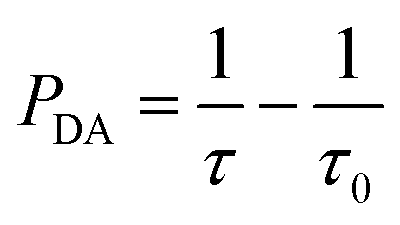
The macroscopic ET rate PDA of the dipole–dipole interaction can be estimated by the lifetime of the donor ions (Eu2+) using:33
 | (2) |
Using eqn (2), the ET rates of the Eu2+–Nd3+ co-doped samples can be evaluated.
As the non-radiative transition in the donors can be neglected according to Dexter,30 the ET efficiency (ηDA) between Eu2+ and Nd3+ can be calculated by:34
 | (3) |
PDA and ηDA are calculated as a function of the Nd3+ concentration and listed in Table 1. The ET rate and efficiency significantly increased upon the Nd3+ introduction. For the SrAl2O4:0.01Eu2+,0.01Nd3+ sample, PDA and ηDA are 0.041 μs−1 and 19.7%, respectively. With the increase in the Nd3+ concentration to 0.10 mol%, ηDA increases to approximately 77.1% with PDA = 0.55 μs−1. The increasing of PDA and ηDA with the introduction of Nd3+ verified that the ET occurred from Eu2+ to Nd3+.
| Nd3+ (mol%) | PDA (μs−1) | ηDA (%) |
|---|---|---|
| 0.01 | 0.041 | 19.7 |
| 0.02 | 0.099 | 37.7 |
| 0.05 | 0.312 | 65.6 |
| 0.10 | 0.550 | 77.1 |
In addition, the theoretical QE of the Eu2+–Nd3+ pair was evaluated by:35
| QE = ηEu(1 − ηDA) + 2ηDA | (4) |
4. Conclusions
A broadband NIR QC was achieved in the SrAl2O4:Eu2+,Nd3+ phosphors. Under the 362 nm excitation, the Nd3+ ion emitted two NIR photons in the range of 800–1200 nm by the CET process from the Eu2+:5d1 state to the Nd3+:4F3/2 state. The optimal QE was 177.1% before the QC occurred. This material can efficiently utilize the broadband solar spectrum in the UV-Vis region; therefore, it might reduce the thermalization loss and thus has significant potentials to increase the conversion efficiency of c-Si solar cells.Conflicts of interest
There are no conflicts to declare.Acknowledgements
This work was supported by the National Natural Science Foundation of China (No. 61775052 and 51675162), Education Department Project of Henan Province (No. 18B150005), Open Research Fund of State Key Laboratory of Transient Optics and Photonics, Chinese Academy of Sciences (SKLST201203), Foundation for University Key Teacher of Henan Province (No. 2013071), Natural Science Fund of Education Department of Shaanxi Provincial Government (Grant No. 16JK1018), Natural Science Fund and Subject Merging Fund of Ankang University for high-level talents (Grant No. 2016AYQDZR05 and 2017AYJC01), and Key Project of Industrial Science and Technology of Shaanxi Province (No. 2016GY-196).Notes and references
- M. Gratzel, Nature, 2001, 414, 338–344 CrossRef CAS PubMed.
- A. Goetzberger, C. Hebling and H. W. Schock, Mater. Sci. Eng., R, 2003, 40, 1–46 CrossRef.
- N. N. Zhang, Y. Zhang, J. Bao, F. Zhang, S. Yan, S. Sun and C. Gao, Chin. Opt. Lett., 2017, 15, 063501 CrossRef.
- S. Gu, P. Zhu, R. Lin, M. Tang, S. Zhu and J. Zhu, Chin. Opt. Lett., 2017, 15, 093501 CrossRef.
- W. Shockley, J. Appl. Phys., 1961, 32, 1402–1403 CrossRef.
- I. M. Dharmadasa, Sol. Energy Mater. Sol. Cells, 2005, 85, 293–300 CrossRef CAS.
- A. J. Nozik, Chem. Phys. Lett., 2008, 457, 3–11 CrossRef CAS.
- D. Timmerman, I. Izeddin, P. Stallinga, I. N. Yassievich and T. Gregorkiewicz, Nat. Photonics, 2008, 2, 105–109 CrossRef CAS.
- B. S. Richard and A. Shalav, Synth. Met., 2005, 154, 61–64 CrossRef CAS.
- B. M. Van Der Ende, L. Aarts and A. Meijerink, Phys. Chem. Chem. Phys., 2009, 11, 11081–11095 RSC.
- T. Trupke, M. A. Green and P. Würfel, J. Appl. Phys., 2002, 92, 1668–1674 CrossRef CAS.
- B. S. Richards, Sol. Energy Mater. Sol. Cells, 2006, 90, 1189–1207 CrossRef CAS.
- J. J. Zhou, Y. X. Zhuang, S. Ye, Y. Teng, B. Zhu, J. H. Xie and J. R. Qiu, Appl. Phys. Lett., 2009, 95, 141101 CrossRef.
- H. Lin, D. Q. Chen, Y. L. Yu, Z. F. Shan, P. Huang, A. P. Yang and Y. S. Wang, J. Alloys Compd., 2011, 509, 3363–3366 CrossRef CAS.
- X. Liu, Y. Teng, Y. Zhuang, J. Xie, Y. Qiao, G. Dong, D. Chen and J. Qiu, Opt. Lett., 2009, 34, 3565–3567 CrossRef CAS PubMed.
- H. Lin, S. Zhou, H. Teng, Y. Li, W. Li, X. Hou and T. Jia, J. Appl. Phys., 2010, 107, 043107 CrossRef.
- Y. Tai, X. Li, X. Du, B. Pan and G. Yuan, RSC Adv., 2018, 8, 23268–23273 RSC.
- A. Jaffrès, B. Viana and E. van der Kolk, Chem. Phys. Lett., 2012, 527, 42–46 CrossRef.
- C. Ming, F. Song, L. An and X. Ren, Curr. Appl. Phys., 2014, 14, 1028–1030 CrossRef.
- Y. Tai, X. Du, X. Li, B. Pan, G. Yuan and H. Wang, J. Photochem. Photobiol., A, 2018, 360, 64–70 CrossRef CAS.
- J. J. Eilers, D. Biner, J. T. van Wijngaarden, K. Krämer, H.-U. Güdel and A. Meijerink, Appl. Phys. Lett., 2010, 96, 151106 CrossRef.
- L. Aarts, B. M. van der Ende and A. Meijerink, J. Appl. Phys., 2009, 106, 023522 CrossRef.
- S. Ye, B. Zhu, J. Chen and J. Luo, Appl. Phys. Lett., 2008, 92, 141112 CrossRef.
- X. Liu, S. Ye, Y. Qiao, G. Dong, B. Zhu, D. Chen, G. Lakshminarayana and J. Qiu, Appl. Phys. B, 2009, 96, 51–55 CrossRef CAS.
- Q. Zhang, C. Yang, Z. Jiang and X. Ji, Appl. Phys. Lett., 2007, 90, 061914 CrossRef.
- Q. Zhang, G. Yang and Z. Jiang, Appl. Phys. Lett., 2007, 91, 051903 CrossRef.
- H. hang, Y. Wang and L. Han, J. Appl. Phys., 2011, 109, 053109 CrossRef.
- Y. Tai, G. Zheng, H. Wang and J. Bai, J. Photochem. Photobiol., A, 2015, 303–304, 80–85 CrossRef CAS.
- L. G. Van Uiter and L. F. Johnson, J. Chem. Phys., 2004, 44, 3514 CrossRef.
- D. L. Dexter, J. Chem. Phys., 1953, 21, 836–850 CrossRef CAS.
- M. A. Chamarro and R. Cases, J. Non-Cryst. Solids, 1989, 107, 178–186 CrossRef CAS.
- S. Tanabe, T. Kouda and T. Hanada, Opt. Mater., 1999, 12, 35–40 CrossRef CAS.
- Z. Nie, J. Zhang, X. Zhang, S. Lü, X. Ren, G. Zhang and X. Wang, J. Solid State Chem., 2007, 180, 2933–2941 CrossRef CAS.
- R. Reisfeld and N. Lieblich-Soffer, J. Solid State Chem., 1979, 28, 391–395 CrossRef CAS.
- D. Chen, Y. Yu, H. Lin, P. Huang, Z. Shan and Y. Wang, Opt. Lett., 2010, 35, 220–222 CrossRef CAS PubMed.
| This journal is © The Royal Society of Chemistry 2018 |