
 Open Access Article
 This Open Access Article is licensed under a Creative Commons Attribution-Non Commercial 3.0 Unported Licence
Thermal annealing assisted synthesis of Sb@C yolk–shell microspheres for sodium-ion batteries†
Feng Sunab,
Qingshan Mab,
Ming Kongab,
Xuefeng Zhoub,
Yan Liub,
Bin Zhou*b,
Ping Zhang*a and
Wen-Hua Zhang *b
*b
aCollege of Materials Science and Engineering, Sichuan University, Chengdu 610064, China. E-mail: zhp@scu.edu.cn
bSichuan Research Center of New Materials, Institute of Chemical Materials, China Academy of Engineering Physics, 596 Yinhe Road, Shuangliu, Chengdu 610200, China. E-mail: whzhang@caep.cn
First published on 31st October 2018
Abstract
Sb@C yolk–shell spheres with tunable interior space have been obtained via a facile thermal annealing strategy and used as anodes for sodium-ion batteries. The proportion of interior space in the yolk–shell structure has a significant influence on the electrochemical performance of the electrode material.
Sodium-ion batteries (SIBs) have gained growing research interests as a viable alternative to lithium-ion batteries (LIBs) owing to the low cost and wide abundance of sodium.1,2 Due to the larger radius of Na+ than Li+, developing proper electrode materials for SIB is more challenging than it is for LIBs.3 For example, the most widely used anode material in commercial LIBs, graphite, shows a very low capacity when used for sodium storage because of the insufficient interlayer distance for hosting the Na+.4 In this context, a great deal of endeavours have been made to explore suitable anode materials with high rate capability and long cycle life for SIBs, such as carbonaceous materials,5–8 metals,9–11 metal oxides,12–14 metal chalcogenides15–18 and metal phosphides.19,20 Among these candidates, metallic Sb show great promise as an anode material for SIBs due to its high theoretical capacity of 660 mA h g−1 for sodium storage and appropriate sodiation potential (about 0.5–0.8 V vs. Na+/Na).3 However, the dramatic volume change of Sb (∼390%) during the sodiation–desodiation process leads to the pulverization of the active material and the loss of electric contact from the current collector, resulting in rapid capacity fading. To circumvent the above issues, a number of strategies have been proposed, including (i) nanostructuring of the metallic Sb,21–23 (ii) constructing Sb–M alloys, where M is a nonelectroactive metal,24,25 (iii) combining Sb with carbon materials.26–28 Among the various approaches, constructing yolk–shell structure, in which Sb yolks are fully encapsulated by a carbon shell, has been proven to be a very effective way to enhance the electrochemical performance of SIBs. The main advantage of this structure is that the carbon shell and large interior void can perfectly accommodate the large volume expansion of the Sb yolk during Na+ insertion, and prevent the cracked Sb particles from losing electric contact. Recently, Liu et al. successfully obtained Sb@C yolk–shell spheres through a nanoconfined galvanic replacement approach, showing excellent electrochemical performance.29 In addition, Song et al. reported a low cost and scalable way for Sb@C yolk–shell structure preparation, by using commercial Sb2O3 powder as starting material.30 They found that the Sb@C yolk–shell structure exhibited much better rate capacity and cycle stability in comparison with bulk Sb.
In the Sb@C yolk–shell structure, the proportion of interior void space in the yolk–shell structure (denoted as ηvoid, ηvoid = interior void space/the whole volume inside carbon shell) is an important structure parameter. It should be large enough to accommodate the large volume expansion of Sb during Na+ insertion. However, the large ηvoid will greatly decreases the gravimetric and volumetric energy densities of the material. Therefore, it is important to comprehensively study the effect of the proportion of interior space in the yolk–shell structure on the electrochemical performance of SIBs. Nevertheless, to date, the synthesis of Sb@C yolk–shell structure with controllable interior space still remains a big challenge.
In this work, Sb@C yolk–shell spheres with controllable interior space are successfully synthesized through a simple carbon-coating method followed by a thermal annealing treatment, and are used as anodes for SIBs. We found that the ηvoid of the yolk–shell structure poses a significant influence on the electrochemical performance of the electrode material. The optimized sample with ηvoid of 74% exhibits considerably better overall performance than other samples, delivering a reversible capacity of 400 mA h g−1 after 300 cycles at a current density of 1 A g−1, thus showing great promise as advanced anode material for SIBs.
Sb microspheres synthesized through a facile solvothermal method are used as the precursors.31 The morphology of the Sb microspheres was examined by transmission electron microscopy (TEM) and scanning electron microscopy (SEM) (Fig. 1a–b and S1†). Sb microspheres with an average diameter of ∼2 μm, exhibit a rough surface. Fig. 1c presents the X-ray diffraction pattern of the as-synthesized Sb microspheres. All of the diffraction peaks can be well-indexed to rhombohedral Sb (JCPDS no. 71-1173). Fig. 1d shows the Raman spectra of the Sb microspheres. The peaks located at ∼115 and 152 cm−1 are characteristic of Raman shifts of antimony.
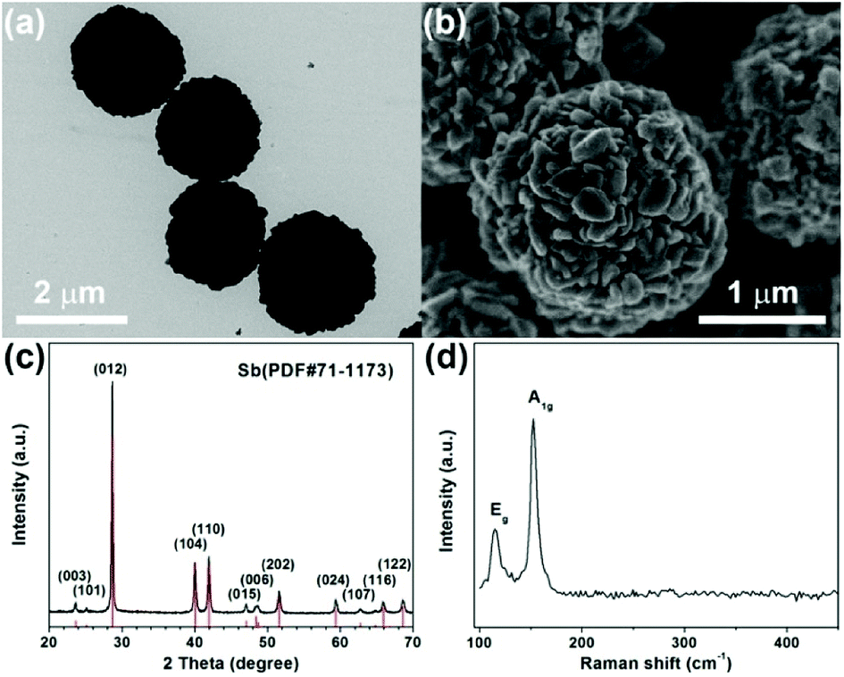 | ||
| Fig. 1 (a) TEM image, (b) SEM image, (c) XRD pattern and (d) Raman spectrum of Sb microspheres. | ||
The specific strategy for the fabrication of Sb@C yolk–shell spheres is illustrated in Fig. 2. First, a uniform and smooth polysaccharide (PA) layer is coated on the surface of Sb microspheres to form Sb@PA core–shell microspheres, via a hydrothermal method in the presence of glucose. TEM image shows that the polysaccharide layer is conformally deposited on the Sb microspheres with a thickness of ∼23 nm (Fig. 2b and S2†). Then, the as-prepared Sb@PA microspheres are annealed at 620 °C in Ar/H2 with different time. During this process, the PA layer is pyrolyzed into carbon shell, leading to the formation of Sb@C core–shell structure. Due to the low melting point, Sb is prone to volatilize at high temperature (above 500 °C).3 Based on this special feature, Sb@C yolk–shell structure with different interior void space can be easily obtained by controlling the annealing time (Sb@C microspheres with annealing time of 30 min, 2 h, 6 h, 12 h are denoted as Sb@C-30 min, Sb@C-2 h, Sb@C-6 h and Sb@C-12 h, respectively). Fig. 2c–f shows the TEM images of Sb@C microspheres. Sb@C-30 min exhibits a core–shell structure, as shown in the enlarged picture of Fig. 2c (Fig. S3†), indicating the volatilization of Sb core is negligible under a short annealing period. When the annealing treatment proceeds to 2 h, many small voids appear between the carbon shell and the Sb core (Fig. 2d). With the extension of annealing time, the void space between the core and shell increases dramatically, giving rise to a typical yolk–shell structure (Fig. 2e–f). Moreover, the whole Sb core could be evaporated, when the annealing time is longer than 48 h (Fig. S4†), resulting in hollow carbon spheres. The XRD patterns of the Sb@C yolk–shell structure matched well with rhombohedral Sb (JCPDS no. 71-1173), precluding the existence of impurities in the products (Fig. S5†). Raman spectra of the Sb@C-6 h are performed and displayed in Fig. S6.† Apart from the typical Raman signals of Sb, two characteristic peaks at 1348 and 1603 cm−1 are observed. These two peaks can be assigned to the disorder-induced phonon mode (D band) and graphite mode (G band) of the carbon shell, respectively. The intensity ratio of the D and G bands (ID/IG) is a descriptor for graphitic degree of the carbon materials. The value of ID/IG is 0.71 for Sb@C microspheres, reflecting the relative disorder and low graphitic degree of the carbon shell.
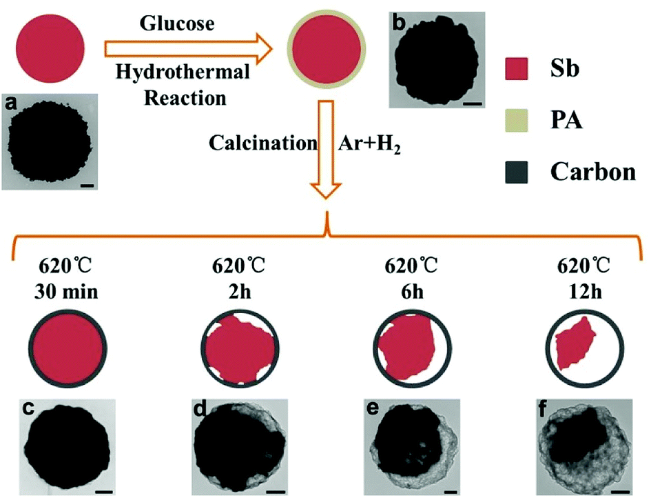 | ||
| Fig. 2 Schematic illustration of the preparation process for the Sb@C yolk–shell Microspheres and typical TEM images of (a) Sb microspheres, (b) Sb@polysaccharide microspheres, (c) Sb@C-30 min, (d) Sb@C-2 h, (e) Sb@C-6 h and (f) Sb@C-12 h. Scale bars = 500 nm. | ||
Due to the similarity of all four samples, Sb@C-6 h is selected for further characterization of the microstructure and elemental distribution of the Sb@C yolk–shell structures. High-resolution transmission electron microscopy (HRTEM) image of Sb@C-6 h clearly shows a 0.31 nm lattice spacing, corresponding to the (012) plane of the rhombohedral Sb (JCPDS no. 71-1173). Moreover, the energy-dispersive X-ray spectroscopy (EDX) elemental mapping results (Fig. 3c–e) of Sb@C-6 h show that the Sb yolk is confined within the carbon framework, further confirming the Sb@C yolk–shell structure.
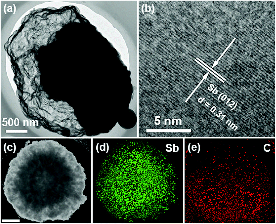 | ||
| Fig. 3 (a) TEM image and (b) HRTEM image of Sb@C-6 h, (c–e) elemental mapping images of Sb@C-6 h. | ||
Thermogravimetric analysis (TGA) is carried out to determine the metallic Sb content in the Sb@C microspheres (Fig. S7†). Based on the weight loss of carbon combustion and the weight gain of Sb2O4 formation, the Sb content in Sb@C-30 min, Sb@C-2 h, Sb@C-6 h and Sb@C-12 h is estimated to be 87%, 83%, 61% and 51%, respectively. According to the eqn (E2) (ESI†), the ηvoid of Sb@C-30 min, Sb@C-2 h, Sb@C-6 h and Sb@C-12 h is calculated to be 0%, 23%, 74% and 88%, respectively. (detailed calculation process can be found in ESI†).
Liu et al. and Song et al. have demonstrated that the Sb@C yolk–shell structure could effectively accommodate the dramatic volumetric expansion of Sb during Li-/Na-ion insertion with excellent electrochemical performance in SIBs.29,30 In this work, it is our main aim to comprehensively study the effect of the proportion of interior space in the Sb@C yolk–shell structure on the electrochemical performance of the SIBs. In this context, the sodium storage performances of Sb@C yolk–shell spheres with different ηvoid were investigated in detail. Fig. 4a shows the cyclic voltammograms of Sb@C-6 h during the first several cycles at a scan rate of 0.1 mV s−1. In accordance with previous reports,23 the first cathodic peak centered at 0.25 V corresponds to the conversion of Sb to NaxSb, while the anodic peak at 0.89 V in anodic scans results from the desodiation reaction of the NaxSb alloy. During the subsequent cathodic scans, three well-separated reduction peaks were observed at 0.64, 0.49, and 0.42 V, corresponding to the formation of amorphous NaxSb, followed by the conversion of amorphous NaxSb to cubic and hexagonal Na3Sb, and ultimately leading to the formation of hexagonal Na3Sb.21,32,33 In the anodic scan, two peaks at 0.86 and 0.92 V almost merge into a broad peak (Fig. S8†), corresponding to the desodiation reactions of Na3Sb and NaxSb, respectively.34 The difference between the first and following cycles is probably attributed to the formation of the solid electrolyte interphase (SEI) layer.3,33 In the subsequent three cycles, the CV curves are nearly overlapped, indicating the good cycling stability of the Sb@C-6 h electrodes. Galvanostatic charge and discharge profiles of Sb@C yolk–shell spheres at a current density of 100 mA g−1 are displayed in Fig. 4b and S9.† Note that all of the specific capacity values in this work are calculated based on the total mass of the Sb@C composites.
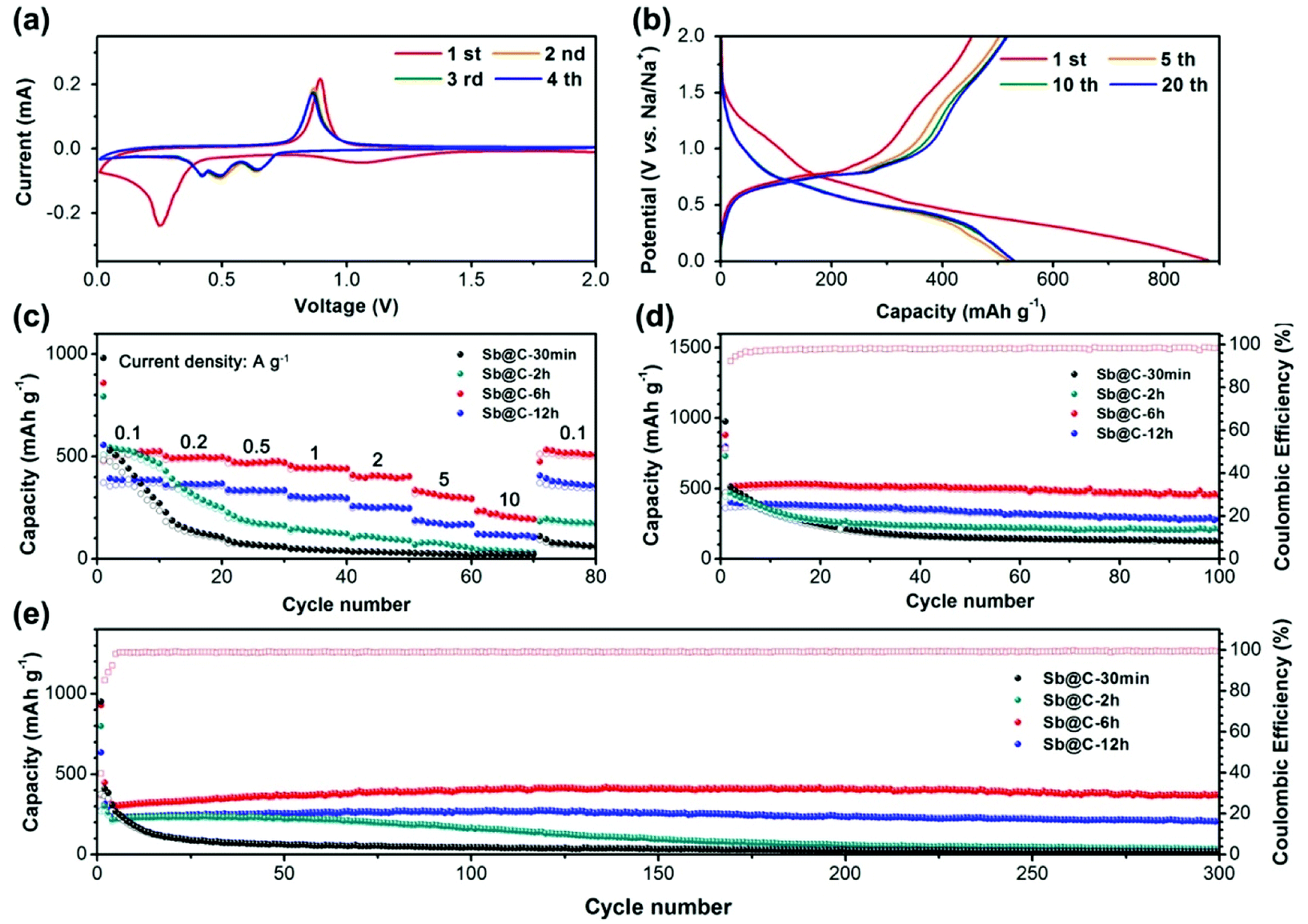 | ||
| Fig. 4 (a) CV curves of Sb@C-6 h at a scan rate of 0.1 mV s−1; (b) galvanostatic charge–discharge profiles of Sb@C-6 h at a current density of 100 mA g−1; (c) rate capability of Sb@C-30 min, Sb@C-2 h, Sb@C-6 h, Sb@C-12 h at various current densities from 100 mA g−1 to 10 A g−1; (d and e) cycling performance of Sb@C-30 min, Sb@C-2 h, Sb@C-6 h and Sb@C-12 h at a current density of 100 mA g−1 and 1 A g−1, respectively. | ||
The initial coulombic efficiencies of the four samples are all close to 50%. The low initial coulombic efficiency is mainly attributed to the formation of SEI films on the Sb core, carbon shell and the carbon conductive additive.33,35 All four samples exhibit a similar sodiation/desodiation plateaus, which is in good agreement with the CV curves. In addition, the voltage profiles of Sb@C-6 h and Sb @C-12 h are well reproducible from 1 to 20 cycles, while the Sb@C-30 min and Sb@C-2 h show rapid capacity decay during the initial 20 cycles. Fig. 4c and d compares the rate and cycling performance of Sb@C-30 min, Sb@C-2 h, Sb@C-6 h and Sb@C-12 h. Among these samples, Sb@C-6 h exhibits a much higher rate capacity and better long term cycling stability than the other three electrodes. Regardless of the lower capacities, Sb@C-12 h exhibits the similar rate and cycling performance to Sb@C-6 h. However, Sb@C-30 min and Sb@C-2 h show a rapid capacity fading and cyclability degradation. The much lower capacity of Sb@C-12 h is due to the lower Sb content in the sample. The good cycling stability of Sb@C-6 h and Sb@C-12 h can be attributed to the large interior void space of these samples. The value of ηvoid of Sb@C-6 h and Sb@C-12 h is 74% and 88%, respectively, which is large enough to accommodate the nearly four times expansion of the Sb core during sodiation, resulting in good cycling performance. The structure stability of Sb@C-6 h and Sb@C-12 h is directly supported by post-mortem SEM characterization (Fig. S10e–h†), which shows that the Sb@C microspheres are well maintained after 300 cycles. In contrast, due to the low ηvoid, Sb@C-30 min (ηvoid = 0%) and Sb@C-2 h (ηvoid = 23%) do not have enough space to buffer the huge volume expansion of Sb, which will cause cracking of the carbon shell, leading to pulverization of the active material and electrical isolation from the current collector, and consequently deteriorate the electrochemical performance. As shown in Fig. S10a–d,† cracked Sb@C microspheres can be obviously observed in the cycled Sb@C-30 min and Sb@C-2 h electrodes, implying the poor structure stability of the Sb@C microsphere with low ηvoid. To gain further insight into the outstanding electrochemical performance of Sb@C-6 h, the AC impedance spectra were measured after the first and the 300th cycle. As shown in Fig. S11,† the semicircle at high frequencies represents the charge-transfer resistance (Rct) and the straight slopping line at low frequencies is attributed to the Na+ diffusion process. After the First cycle, the Rct value of Sb@C-30 min, Sb@C-2 h, Sb@C-6 h and Sb@C-12 h is 262, 237, 181 and 156 Ω, respectively. There is only a little increase in the Rct values of Sb@C-6 h (185 Ω) and Sb@C-12 h (246 Ω) after 300 cycles, indicating a good cycling stability of these electrodes. However, the Rct values of Sb@C-30 min (1282 Ω) and Sb@C-2 h (688 Ω) are increased considerably at the end of 300th cycle, implying a low electrical conductivity, which is probably due to the pulverization of the active material during long-time cycling. These results indicate that the void ratio of the yolk–shell structure have a significant influence on the electrochemical performance of the electrode.
In summary, we have successfully developed a facile thermal annealing assisted approach to synthesize Sb@C yolk–shell microspheres with controllable void space. A series of Sb@C yolk–shell microspheres with different ηvoid were tested as anode materials for SIBs. Remarkably, Sb@C-6 h with a high ηvoid of 74% performed systematically better than the other three samples, delivering a reversible capacity of 400 mA h g−1 after 300 cycles at a current density of 1 A g−1. In contrast, the Sb@C yolk–shell microspheres with low ηvoid exhibited rapid capacity decay. These results suggest that the void ratio of the yolk–shell structure have a significant influence on the electrochemical performance of the electrode material.
Conflicts of interest
There are no conflicts of interest to declare.Acknowledgements
We acknowledge the funding support from the National Natural Science Foundation of China (21805261 and 21701158), China Postdoctoral Science Foundation (2018T110995 and 2018M631101), National Postdoctoral Program for Innovative Talents (BX201700214), and the Science Foundation of Institute of Chemical Materials (011100301).Notes and references
- J. Gu, Z. Du, C. Zhang, J. Ma, B. Li and S. Yang, Adv. Energy Mater., 2017, 7, 1700447 CrossRef.
- D. Kundu, E. Talaie, V. Duffort and L. F. Nazar, Angew. Chem., Int. Ed., 2015, 54, 3431 CrossRef CAS PubMed.
- Z. Liu, X. Yu, X. W. D. Lou and U. Paik, Energy Environ. Sci., 2016, 9, 2314 RSC.
- S. Liu, J. Feng, X. Bian, J. Liu, H. Xu and Y. An, Energy Environ. Sci., 2017, 10, 1222 RSC.
- Z. Li, Z. Jian, X. Wang, I. A. Rodríguez-Pérez, C. Bommier and X. Ji, Chem. Commun., 2017, 53, 2610 RSC.
- L. Xiao, H. Lu, Y. Fang, M. L. Sushko, Y. Cao, X. Ai, H. Yang and J. Liu, Adv. Energy Mater., 2018, 8, 1703238 CrossRef.
- Z. Hong, Y. Zhen, Y. Ruan, M. Kang, K. Zhou, J.-M. Zhang, Z. Huang and M. Wei, Adv. Mater., 2018, 30, 1802035 CrossRef PubMed.
- V. Simone, A. Boulineau, A. de Geyer, D. Rouchon, L. Simonin and S. Martinet, J. Energy Chem., 2016, 25, 761 CrossRef.
- T.-H. Kim, K.-S. Hong, D. Sohn, M. Kim, D.-H. Nam, E. Cho and H. Kwon, J. Mater. Chem. A, 2017, 5, 20304 RSC.
- C. Wang, L. Wang, F. Li, F. Cheng and J. Chen, Adv. Mater., 2017, 29, 1702212 CrossRef PubMed.
- L. Wang, C. Wang, F. Li, F. Cheng and J. Chen, Chem. Commun., 2018, 54, 38 RSC.
- J. Zhou, C. Zheng, H. Wang, J. Yang, P. Hu and L. Guo, Nanoscale, 2016, 8, 17131 RSC.
- D. Ma, Y. Li, H. Mi, S. Luo, P. Zhang, Z. Lin, J. Li and H. Zhang, Angew. Chem., Int. Ed., 2018, 57, 8901 CrossRef CAS PubMed.
- Y. Xu, E. Memarzadeh Lotfabad, H. Wang, B. Farbod, Z. Xu, A. Kohandehghan and D. Mitlin, Chem. Commun., 2013, 49, 8973 RSC.
- Y. Lu, N. Zhang, S. Jiang, Y. Zhang, M. Zhou, Z. Tao, L. A. Archer and J. Chen, Nano Lett., 2017, 17, 3668 CrossRef CAS PubMed.
- X. Xiong, C. Yang, G. Wang, Y. Lin, X. Ou, J.-H. Wang, B. Zhao, M. Liu, Z. Lin and K. Huang, Energy Environ. Sci., 2017, 10, 1757 RSC.
- S. Yuan, Y.-H. Zhu, W. Li, S. Wang, D. Xu, L. Li, Y. Zhang and X.-B. Zhang, Adv. Mater., 2017, 29, 1602469 CrossRef PubMed.
- Z. Wei, L. Wang, M. Zhuo, W. Ni, H. Wang and J. Ma, J. Mater. Chem. A, 2018, 6, 12185 RSC.
- Y. Xu, B. Peng and F. M. Mulder, Adv. Energy Mater., 2018, 1701847 CrossRef.
- J. Zhang, K. Zhang, J. Yang, G.-H. Lee, J. Shin, V. Wing-hei Lau and Y.-M. Kang, Adv. Energy Mater., 2018, 8, 1800283 CrossRef.
- M. He, K. Kravchyk, M. Walter and M. V. Kovalenko, Nano Lett., 2014, 14, 1255 CrossRef CAS PubMed.
- L. Liang, Y. Xu, C. Wang, L. Wen, Y. Fang, Y. Mi, M. Zhou, H. Zhao and Y. Lei, Energy Environ. Sci., 2015, 8, 2954 RSC.
- S. Liu, J. Feng, X. Bian, J. Liu and H. Xu, Energy Environ. Sci., 2016, 9, 1229 RSC.
- L. Wang, C. Wang, N. Zhang, F. Li, F. Cheng and J. Chen, ACS Energy Lett., 2017, 2, 256 CrossRef CAS.
- J. Liu, Y. Wen, P. A. van Aken, J. Maier and Y. Yu, Nano Lett., 2014, 14, 6387 CrossRef CAS PubMed.
- M. Wang, Z. Yang, J. Wang, W. Li, L. Gu and Y. Yu, Small, 2015, 11, 5381 CrossRef CAS PubMed.
- L. Wu, X. Hu, J. Qian, F. Pei, F. Wu, R. Mao, X. Ai, H. Yang and Y. Cao, Energy Environ. Sci., 2014, 7, 323 RSC.
- J. Qian, Y. Chen, L. Wu, Y. Cao, X. Ai and H. Yang, Chem. Commun., 2012, 48, 7070 RSC.
- J. Liu, L. Yu, C. Wu, Y. Wen, K. Yin, F.-K. Chiang, R. Hu, J. Liu, L. Sun, L. Gu, J. Maier, Y. Yu and M. Zhu, Nano Lett., 2017, 17, 2034 CrossRef CAS PubMed.
- J. Song, P. Yan, L. Luo, X. Qi, X. Rong, J. Zheng, B. Xiao, S. Feng, C. Wang, Y.-S. Hu, Y. Lin, V. L. Sprenkle and X. Li, Nano Energy, 2017, 40, 504 CrossRef CAS.
- W. Zhang, L. Xu, G. Xi, W. Yu and Y. Qian, Chem. Lett., 2004, 33, 1476 CrossRef CAS.
- A. Darwiche, C. Marino, M. T. Sougrati, B. Fraisse, L. Stievano and L. Monconduit, J. Am. Chem. Soc., 2012, 134, 20805 CrossRef CAS PubMed.
- H. Hou, M. Jing, Y. Yang, Y. Zhang, Y. Zhu, W. Song, X. Yang and X. Ji, J. Mater. Chem. A, 2015, 3, 2971 RSC.
- N. Zhang, Y. Liu, Y. Lu, X. Han, F. Cheng and J. Chen, Nano Res., 2015, 8, 3384 CrossRef CAS.
- J. Qin, T. Wang, D. Liu, E. Liu, N. Zhao, C. Shi, F. He, L. Ma and C. He, Adv. Mater., 2018, 30, 1704670 CrossRef PubMed.
Footnote |
| † Electronic supplementary information (ESI) available: Experimental details, SEM, TEM, TGA and Raman spectra. See DOI: 10.1039/c8ra07567k |
| This journal is © The Royal Society of Chemistry 2018 |