 Open Access Article
Macro/microbehavior of shale rock under the dynamic impingement of a high-pressure supercritical carbon dioxide jet
Fei Huang *ab and
Bin Huc
aWork Safety Key Lab on Prevention and Control of Gas and Roof Disasters for Southern Coal Mines, Hunan University of Science and Technology, Xiangtan, Hunan 411201, China. E-mail: fhuang@hnust.edu.cn
bHunan Provincial Key Laboratory of Safe Mining Techniques of Coal Mines, Hunan University of Science and Technology, Xiangtan, Hunan 411201, China
cSchool of Resource Environment and Safety Engineering, Hunan University of Science and Technology, Xiangtan, Hunan 411201, China
First published on 13th November 2018
Abstract
This paper focuses on the damage of shale rock impacted by a high-pressure supercritical carbon dioxide (SC-CO2) jet. A well-designed apparatus was used to conduct experiments with a high-pressure SC-CO2 jet impacting shale core plugs. The damage, including the macrofailure and the microchanges of shale samples, was analyzed. The results show that the shale cores develop grid-like fractures on the top surface, while many layered fractures were observed inside the shale cores by means of computed tomography scan. The maximum broken depth of the shale core plugs is dependent upon the combined actions of jet pressure, jet temperature and target distance. The scanning electron microscope images along with the X-ray diffraction results indicate that the shale samples are eroded by the SC-CO2 jet. This erosion may further lead to the macrodamage of shale samples by reducing their mechanical strength.
1. Introduction
Shale gas is one of the most important alternative sources of conventional natural gas. It is known that shale gas reservoirs are characterized by low porosity and low permeability. Reservoir reconstruction must be carried out to extract shale gas. Currently, hydraulic fracturing technology is the main method for reforming shale reservoirs. However, some disadvantages may restrict the wide use of this method: (i) the high content of clay minerals in shale may cause hydrophilic expansion,1 which will cause drilling tools to jam; (ii) the shortage of water resources is another disadvantage; and (iii) the pollution of groundwater by fracturing fluid may cause harm to the environment.2 To overcome the above disadvantages, some special fracturing fluids, such as polymer microsphere emulsion3 and bio-degradable oligo,4 have received increasing attention.SC-CO2 is a type of material in an unconventional phase state. Its density is close to liquid, while its viscosity is close to gas.5 It does not cause clay expansion in the absence of water. Meanwhile, the shale samples absorb SC-CO2 more easily than methane gas. This will cause the sequestration of carbon dioxide and desorption of natural gas.6 Due to the foregoing advantages, SC-CO2 is considered to be an ideal fluid for jet fracturing the shale gas reservoir.7,8 Therefore, the failure laws of shale subjected to the SC-CO2 jet are of great scientific significance.
Kolle used SC-CO2 jets to assist coiled tubing drilling experiments. His results revealed that the SC-CO2 jet can effectively reduce the threshold pressure for rock breaking.9 Du carried out experimental studies on the fracturing of rock with the SC-CO2 jet. The results also showed that the SC-CO2 jet can effectively reduce the rock breaking threshold pressure and cause massive rock crushing.10 Wang conducted the same experiments.11 His results demonstrated that pump pressure, jet temperature, confining pressure, jet distance, rotary speed of core samples and jet time are the main factors influencing the rock-breaking performance and efficiency. Except for the physical impacts, the research results of Li and Jing12 indicated that SC-CO2 immersion will cause damage to the rock and reduce the rock's physical strength. Guo et al.13 found that the mechanical properties of shale rock soaked with SC-CO2 were largely dependent upon the pressure of SC-CO2. Zhang et al.14 conducted simulation experiments on SC-CO2 fracturing in shale. They found that fracturing using SC-CO2 can reduce the pressure needed to initiate fractures by more than 50%. This subject was also studied by Hu et al.15 Lu et al.16 conducted experimental studies on the swelling of shale in supercritical carbon dioxide, which has important consequences with regard to the production of shale gas and the sequestration of CO2 in shale formations. Zhang et al.17 found that significant surface structural changes occurred in shale after saturation with CO2 and brine, and an obvious decrease in the uniaxial compressive strength of shale was observed.
Most of the above studies put their weight on the changes of shale rock subjected to static SC-CO2 fluid. Although some studies have been conducted to research the impact of high-pressure SC-CO2 jet on the changes of rock samples, few studies take shale rock as the experimental sample. This paper plans to study the failure mechanism of shale samples impacted by a SC-CO2 jet at both the macroscopic and microscopic levels.
2. Materials and methods
2.1. Shale samples
Typical shale samples were collected from the Longmaxi Formation of Sichuan Basin's lower Silurian series in the southeastern Chongqing area of China. To keep in line with the actual engineering conditions, the shale samples were tested under undrained conditions. The combined test results of total organic carbon (TOC), thermal maturity (R0) and porosity of the shale in this region indicate that the reservoir is rich in shale gas.18 Moreover, this region has been widely considered to be China's largest and most favorable area for shale gas accumulation.19,20 X-ray diffraction (XRD) analysis shows that the mineral components of the shale mainly consist of quartz, lay minerals (including chlorite, kaolinite and illite), calcite and dolomite. The mass percentages of these components are 52%, 27%, 11% and 9%, respectively.The shale samples were first collected from the outcrop, and then the core plugs were drilled with water from these large blocks of shale. The size of the core plug is 100 millimeters in diameter and 150–250 millimeters in length. Computerized tomography (CT) can be utilized to obtain the internal characteristics of the rock in a nondestructive manner.21 Fig. 1 shows the CT images of the shale core plugs. According to the CT images, it can be observed that the bedding of the shale is well developed. Multiple bedding planes are approximately parallel to each other.
2.2. SC-CO2 jet impacting rock apparatus
The experimental SC-CO2 jet breaking rock apparatus consists of four independent units: a storage unit, a modulation unit, a rock breaking unit, and a recovery unit. The storage unit mainly consists of a CO2 tank and a CO2 supplement device. It is used for the long-term storage of liquid CO2. The CO2 pressure in the container is kept in 3.0–5.0 MPa. The temperature in the tank is kept within a range of −15 to 5 °C. The CO2 supplement device can complement the loss of CO2 during the experiments. The modulation unit mainly consists of a plunger pump and a heater. First, the liquid CO2 is pumped out from the tank and pressurized to the experiment's required pressure. Then, it is heated to the required temperature. Using the above procedure, supercritical CO2 can be created. The experimental unit is illustrated schematically in Fig. 2. It is primarily used to form the SC-CO2 jet and to conduct rock breaking experiments. After modulation, the supercritical CO2 enters the main unit of the rock breaking system through the wellbore inlet. Then, the SC-CO2 is jetting out from the nozzle. The SC-CO2 jet will impact the rock cores at the bottom. Finally, the SC-CO2 will flow into the next unit through the outlet. The recovery unit consists of a solid separator, a liquid separator and a refrigerator. Its main functions are to separate CO2 from the rock debris mixture after the experiments (i.e., to remove debris, water and other impurities). Then, the clean CO2 is converted to liquid form and transported back to the CO2 tank.2.3. Experimental procedure
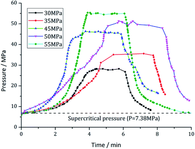
This experiment is mainly intended to study the influence of the pump pressure on the rock-breaking performance. Based on the threshold pressure22 required for rock breaking, pump pressures of 30, 35, 40, 45, 50, and 55 MPa are selected as the experimental pressures. To maintain the supercritical phase of CO2, the temperature of the heater is a variable ranging from 35 °C to 80 °C. The nozzle with an outlet diameter of 2 millimeters is selected. An optimal target distance range of 1 mm to 12 mm is selected according to the findings of Du et al.10 The experimental time was set to 3 minutes for each experimental pressure. Fig. 3 shows the pump pressure changing processes over time. This demonstrates that each experimental pressure sustains approximately 3 minutes. Plunger pump 1 is selected to pressurize the liquid CO2. In this experiment, we assume that the embedded depth of shale rock is about 400 m and the mean density is about 2000 kg m−3. So a confinement pressure of 8 MPa is selected to monitor the deep condition of shale rock. The detailed test parameters are listed in Table 1.| No. | Jet pressure (MPa) | Calculated peak pressure (MPa) | Core diameter (mm) | Core length (mm) | Impacting time (min) | Target distance (mm) | Temperature (°C) | Confining pressure (MPa) |
|---|---|---|---|---|---|---|---|---|
| 1# | 30 | 191 | 100 | 150–200 | 3 | 6 | 50 | 8 |
| 2# | 35 | 210 | 100 | 150–200 | 3 | 6 | 50 | 8 |
| 3# | 40 | 229 | 100 | 150–200 | 3 | 6 | 50 | 8 |
| 4# | 45 | 247 | 100 | 150–200 | 3 | 1/3/6/9/12 | 50 | 8 |
| 5# | 50 | 264 | 100 | 150–200 | 3 | 6 | 35/40/45/50/55 | 8 |
| 6# | 55 | 282 | 100 | 150–200 | 3 | 6 | 50 | 8 |
Firstly, the shale core was wrapped with a Teflon tube. A heat gun was used to shrink the Teflon material in order to keep the shale core wrapped tightly enough. Then the wrapped core was put into the core holder as shown in Fig. 2. Plenty of hydraulic fluid was pumped into the gaps between core holder and Teflon tube until the confinement pressure climbed to ∼8 MPa. This confinement pressure can prevent the incursion of SC-CO2 of which the pressure in the annular space was measured much lower than ∼5 MPa. Thirdly, the baffler was withdrawn and the SC-CO2 jet impacted onto the top surface of shale core. After the impacting, the wrapped shale core was taken down for further test.
3. Results and discussions
3.1. The macrofailure of shale
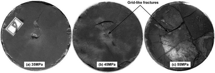
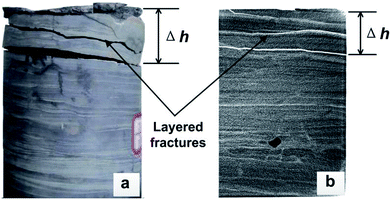
Fig. 4 and 5 show the pictures of shale core plugs impacted by the SC-CO2 jet. It presents a grid-like fragmentation phenomenon on the top surface. When the pump pressure is 30 MPa, no crack appears on the core's end face. Increasing the pump pressure to over 35 MPa, some tiny cracks form in the central area. These initial cracks then extend along the radial direction to the free surface. Multiple cracks connect to each other during crack propagation. Then, cracks in the grid pattern appeared, as shown in Fig. 4. This grid-crack phenomenon becomes increasingly obvious with increasing pump pressure. Finally, shale core plugs may suffer from grid-like massive fracture morphology. From the macroscopic phenomenon in Fig. 4, it can be obtained that the threshold pressure of the shale breaking by the SC-CO2 jet is approximately between 30 and 35 MPa.Computed tomography (CT) scan images show that multiple transverse cracks are generated inside the shale cores shown in Fig. 5. These cracks are parallel to the shale bedding. It is analyzed that they may be caused by the stress waves induced by the impact of the SC-CO2 jet. Once the transverse cracks extend through the rock, the shale debris will be peeled off. Then, the shale core plugs will present what is known as the mass-broken morphology shown in Fig. 4. This morphology is identical to that described in the existing literature.8,11
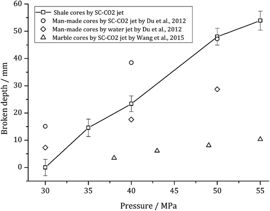
Giving a certain pump pressure, the rock damage will roughly extend to a maximum depth (Δh). Fig. 6 indicates that the damage depth increases linearly with the increasing pump pressure. A linear relationship between Δh and pressures can be described as follows:
| Δh = −64.4 + 2.2P | (1) |
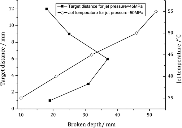
Fig. 7 illustrates the influence of target distance and temperature on the maximum broken depth of shale core plugs. Here, the target distance is defined as the axial distance between the SC-CO2 jet outlet and the head surface of the shale core. The special experimental temperature is controlled by attemperation of the heater. A linearly increasing relationship between the maximum broken depth and the temperature is exhibited in Fig. 7. This trend indirectly indicates that the impact performance of the SC-CO2 jet is positively dependent upon the temperature of the supercritical fluid. The maximum broken depth initially increases sharply with increasing target distance. However, it climbs to a peak value when the target distance increases to approximately 6 mm, above which the broken depth decreases with the target distance. This nonlinear relationship reveals that there may exist an optimal target distance giving a certain nozzle diameter. The impact performance of SC-CO2 is most obvious at this distance. This trend can be explained by the structure of submerged jet. As known, the SC-CO2 jet in this paper is a submerged jet. Its edge diffuses outwards after jetting from nozzle exit. Hence the diameter of jet will increase along the jet axis. On the other hand, the mean velocity of jet decreases from nozzle exit. Then the impact force is the product of cross-sectional area multiply by jet pressure which is proportional to the square of mean velocity. Giving the condition of jet diameter increasing while mean velocity decreasing at the same time, there may exist a point where the impact force is most large. In this experiment, a distance of about three times of the nozzle outlet diameter is found to be the optimal one. But this optimal target distance can be changeable with the jet diameter.
3.2. The microchanges of shale
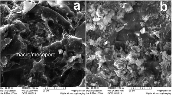
Fig. 8 shows the scanning electron microscope (SEM) images of the shale samples before and after erosion with a magnification of 2000 times. According to the SEM images, quartz, calcite and some other minerals compose the basic skeleton of the shale. The clay minerals and other organic matter fill the voids. A small number of medium and large pores with sizes between 0.1 and 5 μm are observed (Fig. 8(a)). After erosion by the SC-CO2 jet, the microscopic structure of the shale is significantly damaged. In detail, the amounts of clay mineral, organic matter and other filling materials are significantly reduced. The original pores are no longer obvious. Overall, the shale sample shows a disordered microstructure after erosion by SC-CO2 jet (Fig. 8(b)).Two factors may account for the microstructure change. First, the impact load of the SC-CO2 jet acts as a key factor. The process of high-speed fluids impacting solids can be divided into two typical stages: the water hammer pressure stage and the stagnation pressure stage.24 The water hammer pressure is usually dozens of times the stagnation pressure and is generally accepted as the cause of crack initiation. It can be described by the following expression without consideration of the tiny deformations of the solid:25
| Pw = ρCv | (2) |
| Shale samples | SiO2 | Al2O3 | Fe2O3 | K2O | MgO | TiO2 | SO3 | CaO |
|---|---|---|---|---|---|---|---|---|
| Original shale | 71.0364 | 14.9380 | 5.5275 | 3.9739 | 2.1151 | 1.1079 | 0.5372 | 0.3345 |
| Eroded shale | 70.0282 | 14.0077 | 5.4708 | 4.2188 | 1.6983 | 1.2722 | 0.5847 | 1.7832 |
Second, CO2 is corrosive in the presence of water. SEM studies show that CO2 can cause significant corrosion damage to shale samples in high-pressure environments.26 This shows that CO2 mainly acts on clay minerals and organic matter. The literature27 shows that the organic matter inside the shale decomposes upon exposure to SC-CO2. Finally, the decomposition ingredients may block the original medium/large pores. Another literature28 also shows that SC-CO2 acts on the kerogen and causes the decomposition of organic debris during the extraction of petroleum from oil shale by means of supercritical fluid extraction. It is known that the activity of SC-CO2 can be greatly enhanced in a high-temperature and high-pressure environment. This may promote the decomposition of organic matter in the shale while blocking the original pores and thus reducing the physical strength of the shale.29 A contrast experiment was conducted to measure the mechanics change between natural and SC-CO2 eroded shale samples at the same condition as in this paper.30 It's presented that the tensile strength of shale sample eroded by SC-CO2 decreases by 18.3% and the triaxial compressive strength by 8.3% respectively. Hence, it can be inferred that the erosion of SC-CO2 fluid can reduce the mechanics strength of shale sample by changing its microstructure.
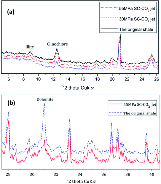
According to the above references, the clay minerals in shale may decompose as a result of the corrosion of SC-CO2. Fig. 9 shows the XRD spectra of the shale samples. After erosion by the 30 MPa SC-CO2 jet for 3 min, there was no change in the clay contents; after erosion by the 55 MPa SC-CO2 jet for 3 min, the contents of illite and clinochlore decreased significantly, as shown in Fig. 9a. The CO2 reacted with the pore water, and the carbonic acid generated. Under high-temperature and high-pressure conditions, the acidic environment will cause the decomposition of illite and clinochlore.31 In addition to the decomposition of clay minerals, an obvious decrease of dolomite can be observed according to the XRD spectra, as shown in Fig. 9b.
In natural shale gas reservoirs, the decomposition reaction of clay minerals affected by CO2 may take a long time, even as long as several years. In this experiment, the decomposition duration of the clay minerals is significantly shortened. First, the physical impact of the high-speed SC-CO2 jet may lead to the rapid decomposition of clay minerals. Then, the high temperature can accelerate the reaction of CO2 with clay minerals.32,33 However, due to the relatively short duration of the experiments, the decomposition of the clay minerals may not be complete, and changes of other minerals are not observed by semiquantitative XRD analysis.
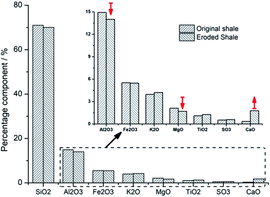
X-ray fluorescence was used to analyze the changes of the shale components before and after the SC-CO2 jet impacting. The exact percentage of some major component of shale samples is illustrated in Table 2. Fig. 10 is the histogram showing the contrast of components in shale samples before and after the SC-CO2 jet impacting. The obvious decreases of aluminum oxide and magnesium oxide are observed in the histogram. These two oxides are the main components of clay minerals. The changes of these two oxides further strengthen the finding of clay mineral decomposition after the SC-CO2 jet impacting. However, a large increase in calcium oxide is observed in Fig. 10. This increase has a close connection with the adsorption of carbon by shale samples, which is discussed in detail in the following section.
3.3. The adsorption of carbon on the shale surface
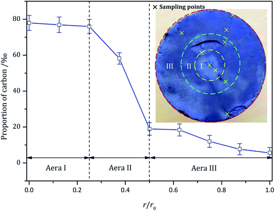
According to Fig. 4, multiple radial cracks were generated on the top surface. Along the radial cracks, multiple samples were selected equidistantly to test the carbon content. The relationship between the carbon content and the radial distance is shown in Fig. 11. A nonlinear fitting of the test data is shown in Fig. 11. It can be expressed as follows:
 | (3) |
The change in carbon content indicates that the shale can absorb CO2. A large number of studies have shown that shale has sequestration characteristics for supercritical, gaseous and liquid CO2.31,34,35 In previous experimental studies, CO2 acted on shale in static form. The action duration of the CO2 was relatively longer. However, in this experiment, CO2 was in the form of supercritical jets. In Fig. 10, Area I is the direct erosion area of the SC-CO2 jet. Area II is the action area of the SC-CO2 radial jet. Lastly, Area III is the action area of the SC-CO2 back flow. According to the test data, the carbon content increases significantly when subjected to the direct erosion of the SC-CO2 jet. This indicates that the interaction between the SC-CO2 jet and the shale sample contributes to the adsorption of CO2 in shale.
4. Discussion
According to the studies by Kolle and Du et al., the method of rock breaking by SC-CO2 jet has the advantages of low threshold pressures and volume breakage.8,10 It is inferred that the combined action of three main factors may cause the shale-breaking phenomenon. They are the jet impact load, the corrosion properties of CO2 at high-temperature and under high-pressure conditions, and the bedding characteristics of shale.First, the impact load of the SC-CO2 jet is the dominant factor leading to shale breakage. It is known that the water hammer pressure induced at the initial stage by the impact load spreads radially in the form of stress waves. These waves include the Rayleigh wave and the body wave (i.e., longitudinal and transverse waves).36,37 According to eqn (2), the water hammer pressure can reach a magnitude near 0.2 GPa (Table 2). On the shale surface, the Rayleigh waves produce a shear stress component and a tensile stress component.38 These large shear stress components and tensile stress components first induce the generation of initial cracks on the shale surface. As a result, the propagation of Rayleigh waves may account for the grid-like fragmentation phenomenon on the shale surface.
Second, the water hammer pressure spreads inside the shale in the form of spherical stress waves. It is known that the reflection of waves could enhance the tensile stress in certain areas inside the shale. The tensile strength of the shale is much lower than the compressive strength (Table 1). Therefore, initial cracks will be generated in these enhanced areas. Then, it can be observed that multiple beddings are nearly parallel to each other from the CT images in Fig. 1. These beddings further weaken the tensile strength of the shale sample and cause the initial cracks to extend along the bedding planes under tensile stress. This is the direct cause for the macroscopically visible transverse cracks seen in Fig. 5. The SEM method is applied to investigate the foregoing assumptions. It can be observed from the SEM images that the surfaces of transverse cracks are stratified. This stratification agrees with the typical character of tensile fracture (Fig. 12(a) and (b)). On the other hand, the surfaces of longitudinal cracks are disordered (Fig. 12(c) and (d)). These cracks may be the result of shear stress.
Third, from the SEM images and XRD semiqualitative analysis, it can be seen that SC-CO2 fluid has changed the microscopic structures and the component compositions of shale material. Therefore, it can be inferred that the physical and mechanical strength of shale samples could be weakened after erosion. Shale erosion occurs in the area where it is directly subjected to the SC-CO2 jet. Thus, the breakage of shale samples in this area is much easier. The grid-like fragmentation phenomenon may be the result of erosion.
5. Conclusions
According to the experimental studies, SC-CO2 jet could effectively promote the decomposition of clay minerals. Meanwhile, the jet impact could change the microstructures of shale samples. According to the change laws of carbon content on the shale surface, the shale sample could absorb supercritical CO2. The shale sample takes on the phenomenon of massive layered breakage subjected to the SC-CO2 jet. This could be caused by the following key factors. First, the stress wave induced by the dynamic load of the SC-CO2 jet impact is the dominant factor. Then, the erosion of shale samples by SC-CO2 under high-pressure and high-temperature environments is an auxiliary factor. Third, the parallel bedding feature of the shale sample is the internal factor. However, due to the restrictions of the core plug sizes and the pump pressures, the above findings may have certain limitations. Subsequent experimental studies will be conducted to supplement the existing results. Overall, the method of SC-CO2 jet breaking shale is valid and feasible.Conflicts of interest
There are no conflicts to declare.Acknowledgements
This work is jointly supported by the National Natural Science Foundation of China (No. 51804115 and 51604092), and the Natural Science Foundation of Hunan Province (No. 2017JJ3072).References
- S. Gou, T. Yin, Q. Xia and Q. Guo, RSC Adv., 2015, 5, 32064–32071 RSC.
- W. Chen, C. Zou, X. Li and L. Li, RSC Adv., 2016, 6, 90682–90689 RSC.
- J. Xu, Z. Qiu, X. Zhao, T. Mou and H. Zhong, RSC Adv., 2018, 8, 20852–20861 RSC.
- Y. Xuan, G. Jiang, Y. Li and X. Zhang, RSC Adv., 2015, 5, 84947–84958 RSC.
- Phase diagram of carbon dioxide, Source: https://www.chemicalogic.com.
- H. Sun, W. Sun, H. Zhao, Y. Sun and D. Zhang, RSC Adv., 2016, 6, 32770–32778 RSC.
- P. J. Jarboe, P. A. Candela, W. L. Zhu and A. J. Kaufman, Energy Fuels, 2015, 29, 7897–7909 CrossRef CAS.
- H. Wang, G. Li and Z. Shen, Energy Sources, 2012, 34, 1426–1435 CrossRef CAS.
- J. J. Kolle, SPE J., 2000, 65534 Search PubMed.
- Y. K. Du, R. H. Wang, H. J. Ni and M. K. Li, Journal of Hydrodynamics, 2012, 24, 554–560 CrossRef.
- H. Wang, G. Li, Z. Shen, S. Tian and B. Sun, J. Pet. Sci. Eng., 2015, 127, 305–310 CrossRef CAS.
- Q. Li and M. Jing, Chin. J. Rock Mech. Eng., 2013, 32, 2205–2213 Search PubMed.
- X. Guo, H. Ni, M. Li, L. Zhang and Y. Wang, Indian Geotech. J., 2018, 48, 1–8 CrossRef.
- X. Zhang, Y. Lu, J. Tang, Z. Zhou and Y. Liao, Fuel, 2016, 190, 370–378 CrossRef.
- Y. Hu, Y. Liu, C. Cai, Y. Kang and X. wang, Appl. Sci., 2017, 7, 1093 CrossRef.
- Y. Lu, X. Ao, J. Tang, Y. Jia and X. Zhang, J. Nat. Gas Sci. Eng., 2016, 30, 268–275 CrossRef CAS.
- S. Zhang, X. Xian, J. Zhou and L. Zhang, RSC Adv., 2017, 7, 42946–42955 RSC.
- S. Chen, Y. Zhu, H. Wang, H. Liu and W. Wei, Energy, 2011, 36, 6609–6616 CrossRef CAS.
- X. Zhao, J. Kang and B. Lan, Renewable Sustainable Energy Rev., 2013, 21, 603–613 CrossRef.
- C. Yue, S. Li, H. Wen, F. Yang and X. Xu, RSC Adv., 2018, 8, 6436–6443 RSC.
- M. Nasseri, F. Rezanezhad and R. Young, Int. J. Fract., 2011, 168, 1–13 CrossRef CAS.
- A. W. Momber, Wear, 2004, 256, 1190–1195 CrossRef CAS.
- Y. K. Du, R. H. Wang, H. Ni, H. J. Huo, Z. Huang, W. Yue, H. Zhao and B. Zhao, J. China Univ. Petrol., 2012, 36, 93–96 Search PubMed.
- J. E. Field, Wear, 1999, 233, 1–12 CrossRef.
- S. S. Cook, Proc. R. Soc. London, Ser. A, 1928, 119, 418–488 CrossRef.
- R. Lahann, M. Mastalerz, J. Rupp and A. Drobniak, Int. J. Coal Geol., 2013, 108, 2–9 CrossRef CAS.
- M. Angeli, M. Soldal, E. Skurtveit and E. Aker, Energy Procedia, 2009, 1, 3351–3358 CrossRef CAS.
- M. Allawzi, A. Al-Otoom, H. Allaboun, A. Ajlouni and F. A. Nseirat, Fuel Process. Technol., 2011, 92, 2016–2023 CrossRef CAS.
- T. F. Xu, J. A. Apps and K. Pruess, Chem. Geol., 2005, 217, 295–318 CrossRef CAS.
- J. Tang, Y. Lu, Y. Chen, X. Zhang, X. Ao, Y. Jia and Q. Li, Rock Soil Mech., 2018, 39, 797–802 Search PubMed.
- B. L. Alemu, P. Aagaard, I. A. Munz and E. Skurtveit, Appl. Geochem., 2011, 26, 1975–1989 CrossRef CAS.
- C. Fouillac, B. Sanjuan, S. Gentier and I. Czernichowski-Lauriol, Third Annual Conference on Carbon Capture and Sequestration, Alexandria, VA, May 3–6, 2004 Search PubMed.
- A. Busch, S. Alles, Y. Gensterblum, D. Prinz and D. N. Dewhurst, Int. J. Greenhouse Gas Control, 2008, 2, 297–308 CrossRef CAS.
- J. Wollenweber, S. Alles, A. Busch, B. M. Krooss and H. Stanjek, Int. J. Greenhouse Gas Control, 2010, 4, 231–241 CrossRef CAS.
- T. R. Elliot and M. A. Celia, Environ. Sci. Technol., 2012, 46, 4223–4227 CrossRef CAS PubMed.
- F. P. Bowden and J. E. Field, Proc. R. Soc. London, Ser. A, 1964, 282, 331–352 CrossRef.
- Y. Zhao, L. Zhang, W. Wang, W. Wan and S. Li, Rock Mech. Rock Eng., 2017, 50, 1–16 CrossRef.
- M. V. Swain and J. T. Hagan, J. Mater. Sci., 1980, 15, 387–404 CrossRef.
| This journal is © The Royal Society of Chemistry 2018 |


