
 Open Access Article
 This Open Access Article is licensed under a Creative Commons Attribution-Non Commercial 3.0 Unported Licence
Toughening of POSS–MPS composites with low dielectric constant prepared with structure controllable micro/mesoporous nanoparticles
Jian Jiao *,
Yudi Shao,
Fenchao Huang,
Jia Wang and
Zhenzhen Wu
*,
Yudi Shao,
Fenchao Huang,
Jia Wang and
Zhenzhen Wu
Department of Applied Chemistry, School of Science, Northwestern Polytechnical University, Xi' an, 710072, P. R. China. E-mail: jjiao@nwpu.edu.cn
First published on 5th December 2018
Abstract
In this work, we developed a modified calcination and extraction method to obtain controllable micro/mesoporous nanoparticle samples POSS–MPS, which were synthesized through glycidyl polyhedral oligomeric silsesquioxane (G-POSS) grafting with aminopropyl-functionalized mesoporous silica (AP-MPS). The POSS–MPS was introduced into the cyanate ester (CE) matrix to optimize the dielectric properties and enhance the toughness of the POSS–MPS/CE nanocomposite. The structure of the hybrid was characterized by FTIR and SEM. The dispersion properties, mechanical properties, dielectric properties and thermal performance were also studied. The results showed that both the C-POSS–MPS and E-POSS–MPS uniformly distribute in the CE matrix with the content of 0.5–4 wt%. The impact strength increased 52% and 60% separately with 2 wt% C-POSS–MPS and E-POSS–MPS addition respectively. The introduction of E-POSS–MPS particles can significantly decrease the dielectric loss value of the POSS–MPS/CE composites to 0.00498, which is of potential in wave transparent composites and structures.
1. Introduction
With the rapid development of wave-transmitting materials, there has been an increasing demand for high-performance materials. Cyanate ester (CE), a thermosetting resin which possesses excellent properties including electrical and thermal conductivities, good chemical stability, mechanical properties and low shrinkage and moisture absorption rate, is widely used in the aerospace field.1–3 However, the main weakness of CE is the high brittleness after curing and this restricts its extensive application from the mechanics viewpoint.4–6The common method to improve toughness in a material is incorporating toughening modifiers, such as elastomers, thermoplastics, thermosetting resins, and organic or inorganic fillers,7–10 into polymers. These could improve the impact strength of material, but its dielectric properties and heat resistance show a decline accordingly. A common method to obtain polymer materials with low dielectric constant is adding fluorine atoms11,12 or aromatic compounds13 into polymers to introduce free volume and minimize polarizability, and eventually synthesize porous polymers.
The polyhedral oligomeric silsesquioxane (POSS)14–17 with organic–inorganic hybrid three-dimensional cage-like structure, can provide the internal structure free volume and void ratio. Recently, POSS/polymer hybrids have attracted much attention owing to the toughness and dielectric properties resulting from the inherently ultra-low dielectric constant and the cage-like structure of POSS. For example, Zhang et al.18 reported the dielectric properties of hydroxyl POSS/PI hybrid materials and indicated that the dielectric constant of materials with 10 wt% loading of POSS declined from 3.36 to 2.51. Chen et al.19 synthesized a polyimide-based nanocomposite with a low dielectric constant of 2.2. However, as nanoparticles, the POSS have high surface energy and are easily agglomerate. So aligned graft modification is needed to improve its dispersion properties.20–23
In order to promote the dispersion of POSS particles and ensure the dielectric properties of the material, the mesoporous silica (MPS)24,25 is used to prepare the modified material. Hui Pan et al. prepared a series of silica nanoparticles surface-modified with MPS, which exhibited excellent dispersibility in various solvents or polymer matrix.26 MPS could provide a large amount of voids in the composites emphasizes the presence of a rigid percolation network via hydrogen bonding.27
With the loading of modified-MPS was increased from 0 to 4 wt% the dielectric constant decrease from 3.27 to 2.78.28
In this study, combining advantages of POSS and MPS is a promising method to prepare materials with lower dielectric constant (κ) and improved thermal and mechanical properties. The amino modified MPS improves interface interaction through the reaction between the functional groups of POSS and the resin matrix, providing good compatibility of POSS with the matrix and achieves molecular level dispersion. The POSS–MPS was used as a novel organic–inorganic hybrid nano-particle for CE resin addition.
The POSS–MPS was synthesized by both calcinations process and extraction process. The effects of different modification methods on the structure of nano-mesoporous materials and the influences caused by this structure on POSS–MPS/CE system were also studied. It indicated that G-POSS provide more reaction groups to reinforce the interface interaction between the CE and silica center, and also introduce more voids in the composites through its enclosing function to MPS. The dielectric properties, mechanical properties, and thermal properties of POSS–MPS/CE composites were investigated. And the structures of POSS–MPS were also studied to demonstrate the function of POSS–MPS.
2. Experimental
2.1 Materials
Glycidyl polyhedral oligomeric silsesquioxane (G-POSS) with eight epoxy groups was obtained from Hybrid Plastics. Bisphenol A cyanate ester (CE) was received from Jiangsu Wuqiao Resin Factory Co., Ltd., China. Tetraethyl orthosilicate (TEOS) was purchased from Aldrich Chemical Co., Ltd., China. α,ω-Polyoxypropylene diamine H2NCH(CH3)CH2[OCH2CH(CH3)]33NH2 (Jeffamine D2000) was supplied by Huntsman Chemicals Co., Ltd., China. γ-Aminopropyltriethoxysilane (APTES) was obtained from Nanjing Crompton Shuguang Organosilicon Specialties Co., Ltd., China. Methylbenzene was purchased from Fuyu Fine Chemical Industry Co., Ltd., China.2.2 Synthesis of POSS–MPS
Surface amino-functionalized MPS particles (denoted AP-MPS) are synthesized by both calcinations method and extraction method.Mesoporous silicas were synthesized according to ref. 29, the Jeffamine D2000 surfactant was dissolved in ethanol and then the certain amount of deionized water was added under stirring. Subsequently, TEOS was added to the surfactant solution under vigorous stirring at ambient temperature. The resulting mixture was then shaked in a heated water bath at 65 °C for 20 h. Afterwards, the as-made products were collected by filtration and wash to obtain the solid material, the material was further dried at 80 °C overnight to produce as-made-MPS.
The reaction scheme and schematic diagram of different preparation of AP-MPS are shown in the Fig. 1 and 2. The as-made MPS was calcinated at 600 °C for 4 h in air to remove the surfactant D2000, then the MPS suspended in methylbenzene (224 mL) with APTES (0.02 mol) under ultrasonic for 30 min, the mixture was placed into a 500 mL three-neck flask and refluxed at 110 °C for 5 h under stirring. After filtration, washed with ethanol, and dried at 80 °C, the C-AP-MPS was finally obtained.
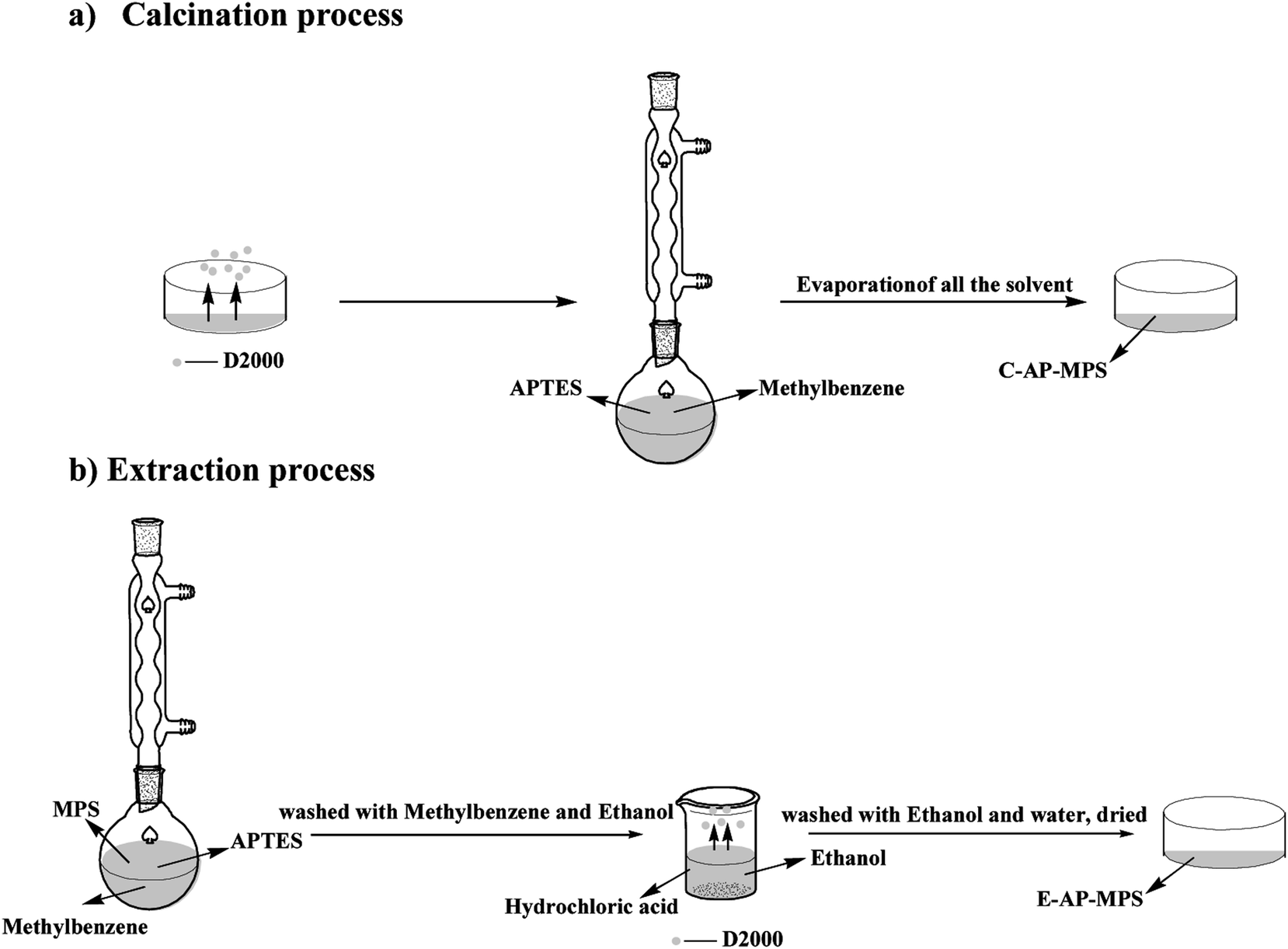 | ||
| Fig. 1 Reaction scheme of different preparation of AP-MPS. (a) is the calcination process and (b) is the extraction process. | ||
 | ||
| Fig. 2 Schematic diagram of different preparation of AP-MPS. | ||
With other conditions unchanged, the AP-MPS obtained by extraction of surfactant D2000 using methylbenzene instead of calcination is named as E-AP-MPS.
POSS–MPS with the mass ratio of G-POSS![[thin space (1/6-em)]](https://www.rsc.org/images/entities/char_2009.gif) :AP-MPS = 4:6 was prepared by the reaction of AP-MPS and G-POSS.
:AP-MPS = 4:6 was prepared by the reaction of AP-MPS and G-POSS.
2.3 Preparation of POSS–MPS/CE composite
The schematic diagram of the preparation of POSS–MPS/CE is shown in Fig. 3. The different loading of POSS–MPS was pretreated by vacuum drying at 80 °C for 12 h and mixed with CE at 110 °C under vigorous stirring to get a homogeneous mixture. The mixture was vacuumized, poured into a mold and cured according to the process of 180 °C/2 h–200 °C/2 h–220 °C/2 h and 240 °C/4 h.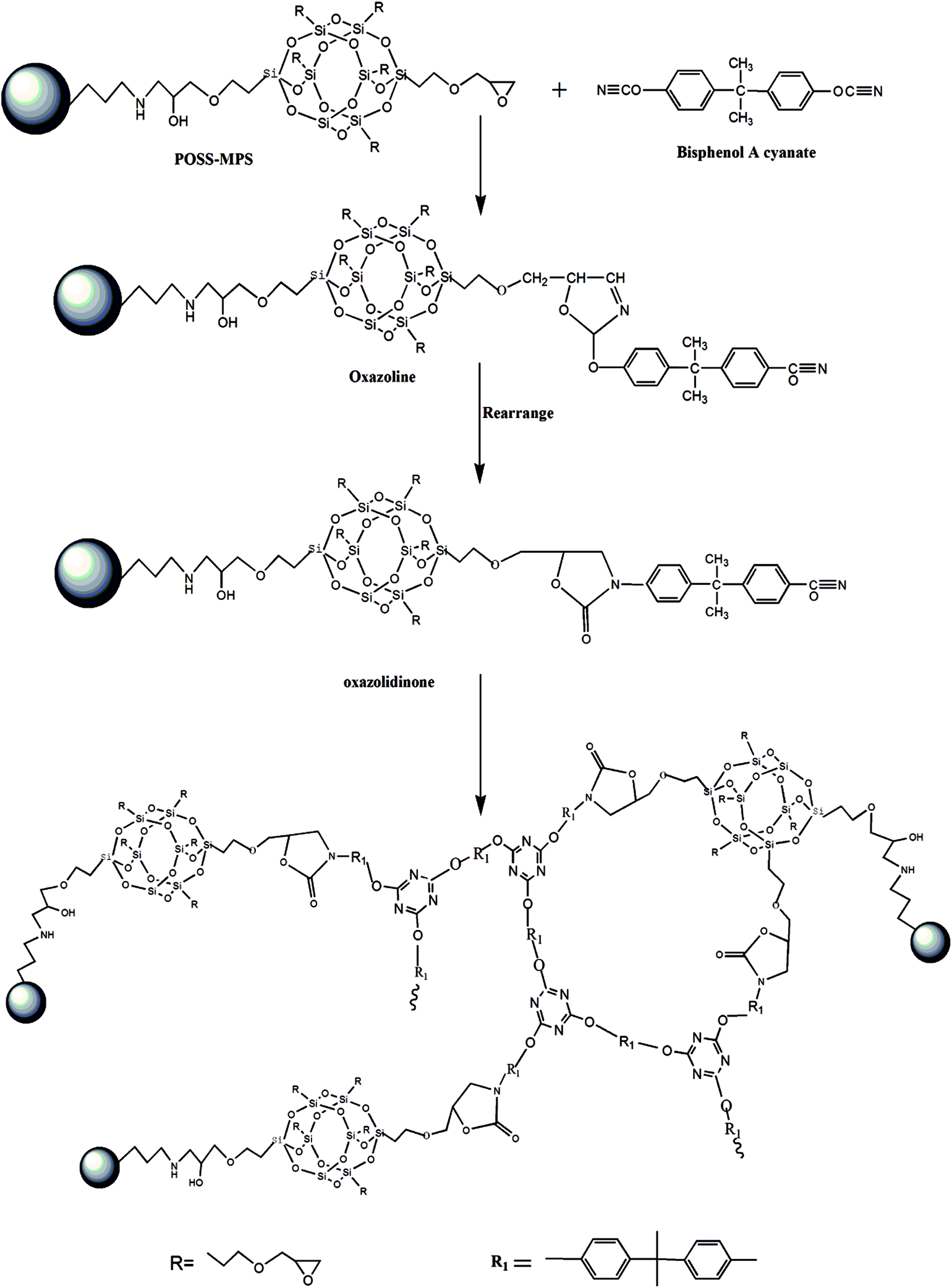 | ||
| Fig. 3 Schematic diagram of preparation of POSS–MPS/CE. | ||
3. Characterization
Fourier transform infrared (FT-IR) spectra of compression molded thin film samples of cured CE and POSS–MPS/CE composites were carried on a IS10 instrument (American Nicolet) and the scan range was 400–4000 cm−1, to determine the functional group of samples. X-ray photoelectron spectroscopy (XPS) was recorded using a Kratos Axis Ultra DLD spectrometer with monochromatic Al Kα X-ray source. N2 adsorption–desorption isotherms were performed at −196 °C using ASPS2020 analyzer with nitrogen, to observe the pore structure of the samples. Scanning electron microscopy (SEM) images of composites were taken on S-2700 microscope of Hitachi Japan, to observe the dispersion of POSS–MPS particles in the CE matrix. Before measurement, the fractural surfaces of the sample were sprayed with gold to increase conductivity. The dielectric properties of composites were measured via a WY2851-frequency Q of Shanghai Wuyi at 25 °C according to GB/T 1409-2006 and the frequency varies from 30 MHz to 60 MHz. Mechanical properties of cured samples were determined at ambient temperature according to GB/T2567-2008 method using a UTM5000 united testing system (Xinsansi, Shenzhen). The performance of impact was tested by using the XCJ-40 (Experimental Factory, Chengde, Hebei). Differential scanning calorimeter (DSC) of the samples were analyzed and characterized using TAMDSC2910 (TA Co. America) in the temperature range of with a heating rate of 10 °C min−1 under N2 atmosphere, to determine the glass transition temperature (Tg).4. Results and discussion
4.1 Structure of surface-modified MPS particles
Fig. 3 presents the corresponding schematic diagram of the preparation process of POSS–MPS. The FT-IR curves of G-POSS, 65-C-MPS, 65-C-AP-MPS, 65-C-40%-POSS–MPS, 65-as-made-MPS, 65-as-made-AP-MPS and 65-E-AP-MPS are shown in Fig. 4. The other peaks in the FTIR are shown in Table 1. The band at 1085 cm−1 refers to the inorganic silica skeleton (Si–O–Si) of the main ingredient samples. It suggests that the structure of the MPS remains intact during the entire process. A peak was observed at 2960–2860 cm−1 of the FTIR spectrum of 65-as-made-MPS refers to the C–H structure, indicating the existence of D2000. It reveals that by extraction method, the D2000 remains in the pore of MPS as expected. | ||
| Fig. 4 FTIR spectra of different stage of the synthesis for (a) POSS-MPS prepared by calcination and (b) POSS-MPS prepared by extraction. | ||
| Wave number (cm−1) | Functional group |
|---|---|
| 1085 | Asymmetric vibrations of Si–O–Si |
| 804 | Symmetrical vibrations of Si–O–Si |
| 1653 | O–H |
| 3440 | Si–OH, –NH2 |
| 908 | Epoxy group |
Further evidence on the successful grafting of the –NH2 onto the MPS can be demonstrated by XPS spectra. Fig. 5 shows the XPS spectra of different stage of the synthesis. Compared with MPS sample (Si 2p, 103 eV), (Si 2s, 152 eV) and (O 1s, 532 eV), characteristic peaks of elements N has been observed in the XPS spectra (N 1s ∼ 399 eV) of AP-MPS, POSS–MPS samples. It is clearly demonstrated that the new element N is introduced to AP-MPS after grafting APTES, which means that the amino group has been successfully grafted onto MPS. The percentage of nitrogen in POSS–MPS is much lower than that of AP-MPS, it is expected that the POSS has been grafted onto the surface of AP-MPS, which reduce the percentage of grafted amino group accordingly.
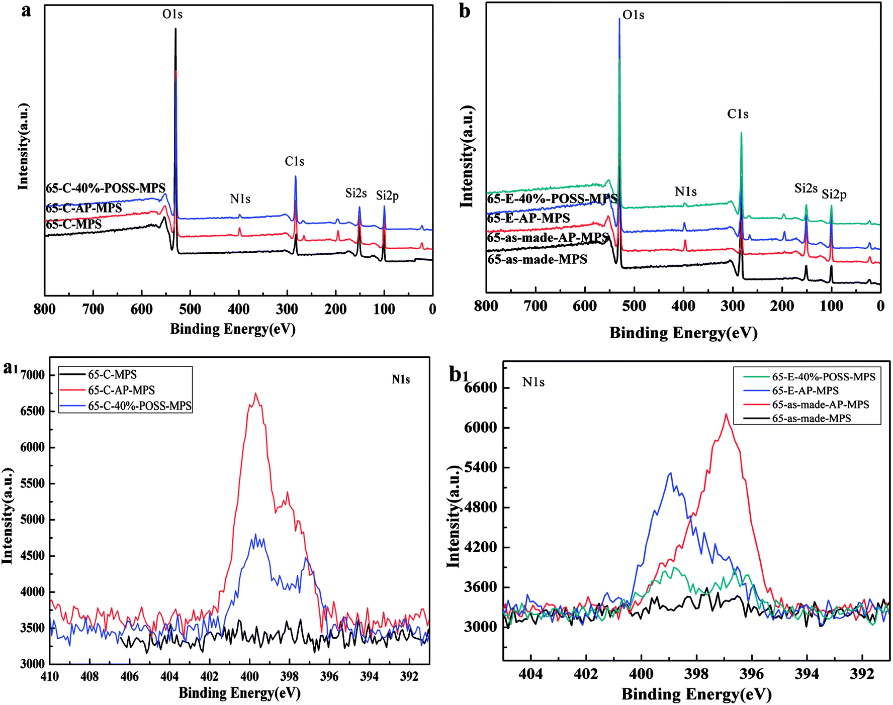 | ||
| Fig. 5 XPS spectra of different stage of the synthesis (a and b) and the N 1s (a1 and b1) of the different stage. | ||
4.2 Microstructure analysis of POSS–MPS
As shown in Fig. 6 and 7, the spherical particle shape and the POSS packed mesoporous structure of the POSS–MPS material are clearly demonstrated by TEM and SEM respectively. The POSS are observed both on the surface and in the pore of MPS. Compared with the E-POSS–MPS, the TEM micrograph of C-POSS–MPS is obscure, which is expected to be POSS in the pore. It reveals that the presence of D2000 in the pore prevents the POSS from entering the pores of MPS, and the extraction method can effectively keep the mesoporous structure intact. The SEM images showed the surface morphology of the particles in different reaction stage. Besides Fig. 7a and d, the modified surfaces of the other four obtained products presented different degrees of roughness, which reflected that the APTES and POSS grafted on MPS successfully.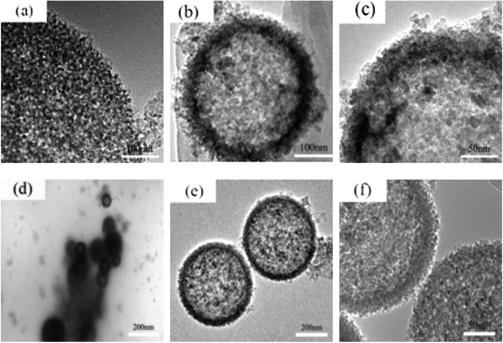 | ||
| Fig. 6 TEM photographs of C-MPS (a), C-AP-MPS (b), C-40%-POSS–MPS (c), as-made-MPS (d), 65-E-AP-MPS (e) and 65-E-40%-POSS–MPS (f). | ||
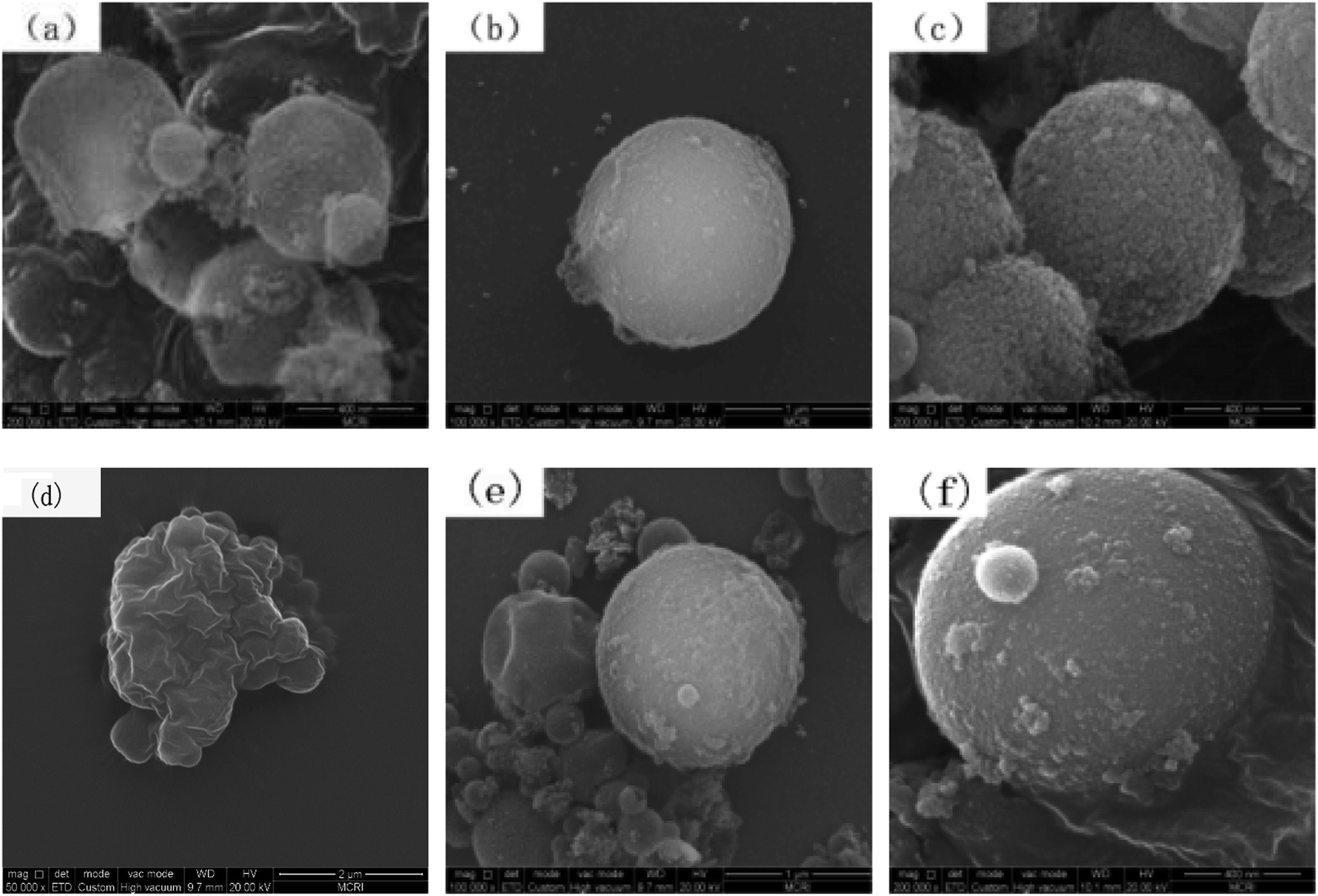 | ||
| Fig. 7 SEM images of the C-MPS (a), C-AP-MPS (b), C-40%-POSS–MPS (c), as-made-MPS (d), E-AP-MPS (e) and E-40%-POSS–MPS (f). | ||
4.3 Physical properties of POSS–MPS
The dare of structural properties of the prepared POSS–MPS were determined using N2 adsorption/desorption. Table 2 implies the mesoporous structure of the MPS, AP-MPS and POSS–MPS. Unlike C-POSS–MPS, the E-POSS–MPS is observed at high relative pressure, indicating a pore enlargement and further confirm the TEM results. Moreover, unlike the pore size distribution curves obtained from C-POSS–MPS samples, the E-POSS–MPS samples produce wider pore size distribution curves. The structural differences show a different pore diameter, which may result from the existence of POSS in the pore of MPS during the calcination process.30 It is suggests that the surfactant D2000 could effectively prevent POSS from incorporating inside the framework of MPS.| Samples | SBET (m2 g−1) | VBJH (cm3 g−1) | DBJH (nm) |
|---|---|---|---|
| 65-as-made-MPS | 2.94 | 0.003 | 4.32 |
| 65-C-MPS | 672.12 | 1.97 | 11.5 |
| 65-C-AP-MPS | 378.30 | 1.26 | 13.5 |
| 65-C-40%-POSS–MPS | 262.56 | 0.64 | 10.0 |
| 65-as-made-AP-MPS | 233.10 | 0.94 | 16.32 |
| 65-E-AP-MPS | 265.72 | 1.08 | 16.39 |
| 65-E-40%-POSS–MPS | 200.22 | 0.60 | 13.48 |
4.4 Dispersion state of POSS–MPS in the CE composites
Fig. 8 shows SEM, EDS-Si and TEM images of the fracture surface for pure CE, C-40%-POSS–MPS-2/CE and E-40%-POSS–MPS-2/CE composites. No phase separation was observed in EDS-Si images, indicating that good dispersion of POSS–MPS was achieved. It can be seen that C-40%-POSS–MPS and E-40%-POSS–MPS are dispersed evenly at a nanometric scale in the CE composite. This may due to the covalent bonding formed between the epoxy groups outside the POSS–MPS and the –OCN groups of CE resin. The pure CE exhibits a smooth fracture surface in Fig. 8a, indicating brittle fracture behavior. However, the sample containing POSS–MPS exhibits a rough fractural surface in Fig. 8b and c, suggesting that the POSS–MPS with inorganic core can induce plastic deformation of matrix. The hybrid material shows many microcracks on the interface between the silica core and organic phase. Such micro-cracks can absorb energy and prevent the crack propagation. It is indicated that the loading of POSS–MPS can improve the strength and toughness of the POSS–MPS/CE composites.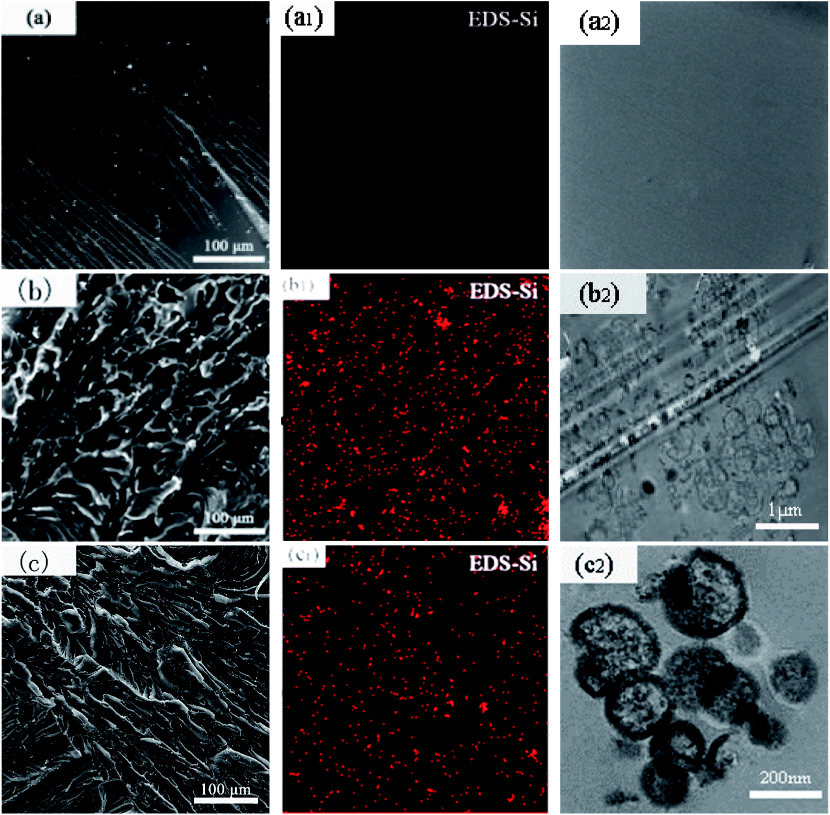 | ||
| Fig. 8 SEM, EDS-Si and TEM images of the fracture surface for pure CE (a, a1 and a2), C-40%-POSS–MPS-2/CE (b, b1 and b2) and E-40%-POSS–MPS-2/CE (c, c1 and c2). | ||
4.5 Dielectric properties of POSS–MPS/CE composites
Fig. 9 presents the dielectric properties of pure CE and POSS–MPS/CE composites. The dielectric responses of the material obtained show different results depending on the type of POSS–MPS. Compared with CE, the two types POSS–MPS composites revealed slightly lower values of dielectric constant. Whereas, it is notable that the dielectric loss value of the POSS–MPS/CE composite were found to be lower when the frequency ranges from 10 MHz to 60 MHz, and it reaches its lowest dielectric constant 2.75 and lowest dielectric loss value 0.00498 at 30 MHz. Wang31 synthesized POSS/CE composites which have a lowest dielectric constant of 3.05 and a lowest dielectric loss value of 0.0084 with 4 wt% loading of POSS. The results indicate the POSS–MPS/CE systems exhibited better dielectric properties in comparison to POSS/CE composites. The introduction of MPS reduces the amount of POSS required.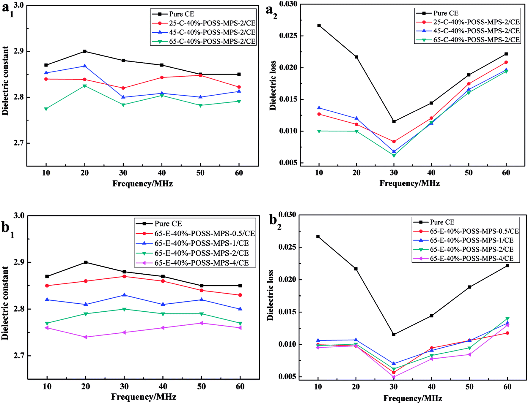 | ||
| Fig. 9 Dielectric constant and loss factor of pure CE and POSS-MPS/CE. (a) The composites with POSS-MPS prepared by calcination, and (b) the composites with POSS-MPS prepared by extraction. | ||
The decrease in κ may be attributed to two reasons. On one hand, silsesquioxanes inherently possess low κ. Incorporation of POSS will inevitably reduce the κ of hybrid materials.18 On the other hand, small amount of POSS–MPS can fill the space between polymeric chains of cyanates and cross-link with –OCN groups as well.30 It seems that the incorporation of POSS in the matrix leads to an immobilization of the side group. The immobilization can be explained by the formation of covalent bonds between POSS and CE due to the reaction of epoxy groups of POSS. And the immobilization leads to lower electric dipole relaxation loss of composites. In addition, we can observe the E-POSS–MPS/CE synthesized by extraction shows lower dielectric loss constant than that of the C-POSS–MPS/CE. It suggests that the E-POSS–MPS with larger bore diameter can improve the pore ratio. It proves that during the extraction process the template agent can effectively protect the pore of MPS.
4.6 Mechanical properties of composites
The mechanical properties are summarized in Table 3. The impact strength of POSS–MPS/CE resin is influenced by the loading of POSS–MPS. POSS–MPS/CE composites have higher impact strengths than CE resin, it can be seen that the impact strengths of C-POSS–MPS-2/CE and E-POSS–MPS-2/CE are about 1.5 and 1.6 times of that of CE resin, respectively. These differences are resulted from their different structure and different pore constant.32 It is obvious that the composites prepared by extraction method have higher flexural strength and flexural modulus than the composites made by the calcinations method. The D2000 in the extraction method prevents the POSS from entering the mesopores, which allows POSS to grafted on the surface of MPS and interact with CE, thus improving the compacity. So the E-POSS–MPS-2/CE has the better flexural property than C-POSS–MPS-2/CE.| Sample | Flexural strength (MPa) | Flexural modulus (GPa) | Impact strengths (kJ m−2) |
|---|---|---|---|
| CE | 98.49 | 3.28 | 9.21 |
| C-POSS–MPS-0.5/CE | 98.82 | 3.36 | 12.92 |
| C-POSS–MPS-1/CE | 105.27 | 3.49 | 14.32 |
| C-POSS–MPS-2/CE | 112.53 | 3.44 | 14.51 |
| C-POSS–MPS-4/CE | 94.89 | 3.36 | 10.03 |
| E-POSS–MPS-0.5/CE | 116.28 | 3.34 | 10.01 |
| E-POSS–MPS-1/CE | 122.92 | 3.52 | 12.47 |
| E-POSS–MPS-2/CE | 130.10 | 3.89 | 13.01 |
| E-POSS–MPS-4/CE | 114.83 | 2.98 | 10.56 |
4.7 Thermal properties of POSS–MPS/CE
The thermal properties of pure CE and POSS–MPS/CE composites can be obtained from Fig. 10. It can be seen that all composite materials show increase in thermal properties. Tg increased when the loading of C-POSS–MPS or E-POSS–MPS increase from 0.5 wt% to 4 wt%. With further increased loading of POSS–MPS, Tg continuously and significantly rise and reach its summit at about 274 °C with 2.0 wt% E-POSS–MPS. This may be that the chemical bridging effect between POSS–MPS and CE matrix can effectively reduce the free volume of the interface region and suppress the mobility of chain segments,33 resulting in the improvement of the Tg value. The Tg of C-POSS–MPS composite shows only slightly increase by 11%, when the Tg of E-POSS–MPS hybrid material increases by 18%. For the POSS–MPS/CE system, the change in Tg with POSS–MPS content can be explained by the change in cross-link densities of the hybrids. Small amount of POSS–MPS can effectively increase the cross-link densities of the hybrid network, leading to the obvious increase in Tg. It is similar to the MPS/CE hybrid material.28 In addition, the E-POSS–MPS with large wormhole, which occupied more volume, affect the movement of molecular chain, so the E-POSS–MPS/CE possess higher Tg. | ||
| Fig. 10 Thermal properties of pure CE and POSS-MPS/CE prepared with (a) POSS-MPS prepared by calcination and (b) POSS-MPS prepared by extraction. | ||
5. Conclusion
In this work, we synthesized the structure controllable POSS–MPS and the properties of POSS–MPS/CE composites with low loadings of POSS–MPS were studied. The C-POSS–MPS and the E-POSS–MPS were obtained by calcinations process and extraction process respectively. The E-POSS–MPS shows higher mechanical properties, thermal properties and dielectric properties than that of the C-POSS–MPS. The main reason is that the pore structure of E-POSS–MPS has been well protected in the extraction process. The larger wormhole framework structures are effective reinforcing agents for a CE polymer. The E-POSS–MPS/CE composites exhibited lower dielectric constant because of its much void. The enhanced mechanical and thermal properties of POSS–MPS/CE composites were ascribed to the addition of POSS–MPS fillers which improved interface interaction and homogeneous distribution of POSS–MPS particles in the CE matrix. In general, incorporation of POSS–MPS by the extraction method is an effective approach to improve the dielectric, mechanical, and thermal properties of CE resin.Conflicts of interest
There are no conflicts to declare.Acknowledgements
The authors gratefully acknowledge the financial support from the Seed Foundation of Innovation and Creation for Graduate Students in Northwestern Polytechnical University (ZZ2018193) and the Natural Science Foundation of China (No. 51373135).References
- Q. L. Lin, L. J. Qu and Q. F. Lu, et al., Preparation and properties of graphene oxide nanosheets/cyanate ester resin composites, Polym. Test., 2013, 32, 330–337 CrossRef CAS
.
- C. P. Sakthidharan, P. R. Sundararajan and M. Sarojadevi, Thermal and mechanical properties of azomethine functionalized cyanate ester/epoxy blends, RSC Adv., 2015, 5, 19666–19674 RSC
- C. Zhou, A. J. Gu and G. Z. Liang, et al., Novel toughened cyanate ester resin with good dielectric properties and thermal stability by copolymerizing with hyperbranched polysiloxane and epoxy resin, Polym. Adv. Technol., 2011, 22, 710–717 CrossRef CAS
- J. Liu, N. D. Ding, R. F. Xu, Q. H. He, J. Shen and B. X. Hu, Cyanate Ester Resin Modified by Hydroxyl-Terminated Polybutadiene: Morphology, Thermal, and Mechanical Properties, Polym. Eng. Sci., 2011, 51, 1404–1408 CrossRef CAS
- Y. Lin, J. Jin, M. Song, S. J. Shaw and C. A. Stone, Curing dynamics and network formation of cyanate ester resin/polyhedral oligomeric silsesquioxane nanocomposites, Polymer, 2011, 52, 1716–1724 CrossRef CAS
- C. Zhou, A. J. Gu, G. Z. Liang and L. Yuan, Novel toughened cyanate ester resin with good dielectric properties and thermal stability by copolymerizing with hyperbranched polysiloxane and epoxy resin, Polym. Adv. Technol., 2011, 22, 710–717 CrossRef CAS
- X. Sheng, R. Hanus, A. Bauer and M. R. Kessler, Effect of PEGDE addition on rheological and mechanical properties of bisphenol E cyanate ester, J. Appl. Polym. Sci., 2013, 130, 463–469 CrossRef CAS
- D. X. Zhuo, A. J. Gu, G. Z. Liang, J. T. Hu and L. Yuan, Preparation and properties of hollow silica tubes/cyanate ester hybrids for high-frequency copper-clad laminates, J. Mater. Sci., 2011, 46, 1571–1580 CrossRef CAS
- A. Chandramohan, K. Dinkaran, A. A. Kumar and M. Alagar, Synthesis and characterization of epoxy modified cyanate ester POSS nanocomposites, High Perform. Polym., 2012, 24, 405–417 CrossRef
- J. Jiao, X. Sun and T. J. Pinnavaia, Mesostructured silica for the reinforcement and toughening of rubbery and glassy epoxy polymers, Polymer, 2009, 50, 983–989 CrossRef CAS
- Z. Y. Ge, Z. Q. Tao and G. Li, et al., Synthesis and properties of novel fluorinated epoxy resins, J. Appl. Polym. Sci., 2011, 120, 148–155 CrossRef CAS
- Z. Q. Taa, S. Y. Yang and Z. Y. Ge, et al., Synthesis and properties of novel fluorinated epoxy resins based on 1,1-bis(4-glycidylesterphenyl)1-(30-trifluoromethylphenyl)-2,2,2-trifluoroethane, Eur. Polym. J., 2007, 43, 55–560 Search PubMed
- X. Y. Zhao, M. Z. Wang and Z. Wang, et al., Structural and dielectric properties of conjugated polynitrile thin films deposited by plasma polymerization, Thin Solid Films, 2008, 516, 8272–8277 CrossRef CAS
- J. Jiao, P. P. Lv and L. Wang, et al., The effects of structure of POSS on the properties of POSS/PMMA hybrid materials, Polym. Eng. Sci., 2015, 55, 565–572 CrossRef CAS
- K. Liang, H. Toghiani and C. U. Pittman, Synthesis, morphology and viscoelastic properties of epoxy/polyhedral oligomeric silsesquioxane (POSS) and epoxy/cyanate ester/POSS nanocomposites, J. Inorg. Organomet. Polym., 2011, 21, 128–142 CrossRef CAS
- K. Liang, H. Toghiani and C. U. Pittman, Synthesis, morphology and viscoelastic properties of epoxy/polyhedral oligomeric silsesquioxane (POSS) and epoxy/cyanate ester/POSS nanocomposites, J. Inorg. Organomet. Polym., 2011, 21, 128–142 CrossRef CAS
- S. Rakesh, C. P. S. Dharan and M. Selladurai, et al., Thermal and mechanical properties of POSS–cyanate ester/epoxy nanocomposites, High Perform. Polym., 2013, 25, 87–96 CrossRef
- Z. P. Zhang, J. Z. Pei and G. Z. Liang, et al., Methyl silsesquioxane/cyanate ester resin organic–inorganic hybrids with low dielectric constant, J. Appl. Polym. Sci., 2011, 121, 1004–1012 CrossRef CAS
- Y. W. Chen and E. T. Kang, New approach to nanocomposites of polyimides containing polyhedral oligomeric silsesquioxane for dielectric applications, Mater.
Lett., 2004, 58, 3716–3719 CrossRef CAS
- P. F. Cao, Z. Wojnarowska, T. Hong, B. Carroll and B. R. Li, et al., A star-shaped single lithium-ion conducting copolymer by grafting a POSS nanoparticle, Polymer, 2017, 124, 117–127 CrossRef CAS
- G. Bayramoglu, M. G. Seker and M. Mudu, Preparation of Methacrylated Polyglycidol-POSS Based Silver Nanoparticle Containing Nanocomposites via Photopolymerization, Prog. Org. Coat., 2016, 101, 510–521 CrossRef CAS
- A. J. Guenthner, C. M. Sahagun, K. R. Lamison and J. T. Reams, et al., Effect of Nanoparticle Functionalization on the Performance of Polycyanurate/Silica Nanocomposites, Ind. Eng. Chem. Res., 2016, 55, 7096–7107 CrossRef CAS
- J. Yu and Z. B. Qiu, Isothermal and Nonisothermal Cold Crystallization Behaviors of Biodegradable Poly(L-lactide)/Octavinyl-Polyhedral Oligomeric Silsesquioxanes Nanocomposites, Ind. Eng. Chem. Res., 2016, 50, 12579–12586 CrossRef
- J. Jiao, L. Wang, P. Lv, P. Liu and Y. Cai, Low dielectric constant nanoporous silica/PMMA nanocomposites with improved thermal and mechanical properties, Mater. Lett., 2013, 109, 158–162 CrossRef CAS
- H. X. Yan and M. M. Zhang, et al., Effects of macromolecular silane coupling agent on the mechanical properties of nano-SiO2/cyanate ester nanocomposites, J. Reinf. Plast. Compos., 2014, 33, 127–136 CrossRef
- H. Pan and G.-L. Li, et al., Preparation, characterization and application of dispersible and spherical Nano-SiO2@Copolymer nanocomposite in leather tanning, Appl. Surf. Sci., 2017, 426, 376–385 CrossRef CAS
- A. Ladhar and A. Ben Mabrouk, et al., Dielectric properties of nanocomposites based on cellulose nanocrystals (CNCs) and poly(styrene-co-2-ethyl hexylacrylate) copolymer, Polymer, 2017, 125, 76–89 CrossRef CAS
- Z. Wu and L.-z. Zhao, et al., Improved Cyanate Resin with Low Dielectric Constant and High Toughness Prepared Using Inorganic–Organic Hybrid Porous Silica, Chem. Lett., 2017, 46, 139–142 CrossRef CAS
- I. Park, Z. Wang and T. J. Pinnavaia, Assembly of large-pore silica mesophases with wormhole framework structures from α,ω-diamine porogens, Chem. Mater., 2005, 17, 383–386 CrossRef CAS
- H. Zhang, G. Zhang and J. Li, et al., Lightweight, multifunctional microcellular PMMA/Fe3O4@MWCNTs nanocomposite foams with efficient electromagnetic interference shielding, Composites, Part A, 2017, 100, 128–138 CrossRef CAS
- L. Wang, J. Jiao and Y. Xu, et al., Preparation and properties of cyanate ester/G-POSS hybrid materials, Eng. Plast. Appl., 2012, 45, 7–10 Search PubMed
- J. T. Hu, A. Gu and Z. Jiang, et al., High efficiency synthesis of octavinylsilsesquioxanes and its high performance hybrids based on bismaleimide-triazine resin, Polym. Adv. Technol., 2012, 23, 1219–1228 CrossRef CAS
- Z. Zhang, G. Liang, X. Wang, S. Adhikari and J. Pei, Curing behavior and dielectric properties of amino-functionalized polyhedral oligomeric silsesquioxane/cyanate ester resin hybrids, High Perform. Polym., 2012, 25, 427–435 CrossRef
| This journal is © The Royal Society of Chemistry 2018 |