
 Open Access Article
 This Open Access Article is licensed under a Creative Commons Attribution-Non Commercial 3.0 Unported Licence
Theoretical study of mechanisms for the hydrolytic deamination of cytosine via steered molecular dynamic simulations†
S. Tolosa*,
J. A. Sansón and
A. Hidalgo
Departamento de Ingeniería Química y Química Física, Universidad de Extremadura, Badajoz, Spain. E-mail: santi@unex.es
First published on 11th October 2018
Abstract
Gibbs free energy profiles of the cytosine deamination assisted by a water molecule in a discrete aqueous medium were obtained by the application of Steered Molecular Dynamic (SMD) simulations. Two pathways were considered to explain the mechanism of this process, where the water molecule attacks the C–N bond to give an intermediate (an amino–hydroxy–oxo structure in the A-path, and a hydroxy–oxo in the B-path) as the determinant step of reaction. Stationary structures along both energy profiles were analyzed at molecular dynamics level, obtaining states with higher free energies than those from electronic calculations in the gas phase and in solution described as a continuous medium. From the results obtained, the more complex A-pathway, with five steps, was kinetically the most favorable (with an endergonic reaction energy of 7.41 kcal mol−1, a high barrier of 67.53 kcal mol−1, and a small velocity constant k2 = 1.80 × 10−37 s−1), concluding that the uracil base can participate in a spontaneous genetic mutation since the uracil–ammonia complex has a long lifetime of 6.10 × 1027 s. This process turns out exergonic and faster when carried out in gas phase simulation or electronic calculation with a continuous medium, due to the disappearance of explicit water molecules that can compete with the assistant molecule.
1. Introduction
Theoretical structural and thermodynamic studies are essential to understand the behavior of a variety of biochemical processes.1–8 These studies are especially important for DNA and RNA acids, as these molecules are responsible for encoding and transmitting the genetic information necessary for proper cellular function, and for converting this information into functional products such as proteins. Despite protection from the cellular medium, these nucleic acids undergo alterations to their structure from attacks by various agents, both physical (ionizing radiation) and chemical (free radicals), which can lead to genetic mutations.9 It is important to note that the nitrogenous bases of these acids are exposed to the physiological medium formed mainly by water molecules. Therefore, the canonical or non-canonical forms of these bases will depend on the surrounding environment in which they are, this medium being capable of modifying the stability and equilibrium constants of the tautomeric processes.10–17 It has been shown that other effects, such as the base-pair stacking in DNA and RNA acid strands, have relevance in proton-transfer reactions.18,19While DNA is a reasonably regular structure formed by two nucleotide chains wrapped around an axis which are held together by hydrogen bonds formed between the base pairs guanine–cytosine (G–C) and adenine–thymine (A–T) (so-called Watson–Crick pairs), RNA is formed by a simple chain of nucleotides similar to that of DNA, except that thymine is replaced by uracil (U). However, modified nucleobases in DNA and RNA are also known to occur, forming rare bases or base pairs that can participate in genetic mutation.
Cytosine is the most unstable of the DNA bases, interacting with other nitrogenous bases via hydrogen bonds, mostly with guanine to give the guanine–cytosine base pair. This DNA base has been extensively studied experimentally and computationally, in both gas and aqueous phase. Its most stable (canonical) form has an amino–keto structure, although there may be other less frequently observed structures, such as the imino–enol structure resulting from the exchange of hydrogen between the amine and keto groups. Its interaction with water has also been the subject of numerous studies due to its conversion into a uracil base and its participation in the genetic mutation. The cytosine(keto)–water complex is more stable than the cytosine(enol)–water complex by 1 kcal mol−1,20 with an interconversion energy barrier between 30 and 37 kcal mol−1.21
As shown in Fig. 1, the hydrolysis of cytosine (C) can lead to a deamination obtaining the uracil base (U) and ammonia (A), i.e. the loss of an amino functional group with conversion to a carbonyl functional group. This process is important in spontaneous genetic mutation since uracil is potentially mutagenic and changes the coding information during DNA replication and RNA transcription. Although this deamination is a rare process under normal physiological conditions, its rate can significantly change in the presence of some reactants (OH−, H+, H2O, NO, HNO2, HSO3− …) that act as catalysts. The reactants are able to reduce the energy barrier of deamination by up to 28 kcal mol−1, with rate constants between 10−10 and 10−13 s−1.22,23
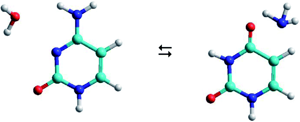 | ||
| Fig. 1 Cytosine–water (C–W) to uracil–ammonia (U–A) conversion. | ||
The C–W ⇆ U–A equilibrium produced by the cytosine deamination is the focus of this work. Specifically, the transference of hydrogen atoms from the water molecule to the nitrogen atoms of cytosine and the transference of the oxygen atom from water to the carbon atom linked to the amine group of cytosine, forming the corresponding uracil–ammonia (U–A) complex. It is known that interconversion between cytosine and uracil bases depends on the surrounding aqueous medium, hence the interest of studies that include the solvent effect. On one side, solvation methods24–26 are the most practical way of taking into account solvent effects when calculating free energies in solution using electronic structure methods. Classical molecular dynamic simulations27 are also a desirable alternative for predicting the evolution of the tautomeric process over time and for visualizing the solute–solvent system at the molecular level. The steered molecular dynamic (SMD) technique,28,29 which applies external steering forces in a particular direction, allows us in a simpler way to determine the changes in Gibbs free energy over the course of any elementary process, and is useful for the study of reaction mechanisms.
There have been some theoretical studies on cytosine–water interactions.20,21,30–43 Most of these studies focus on the gas phase using ab initio methods, although some authors employed a polarizable continuum model (PCM) or a mechanic molecular (MM) to describe the solvent. We can say that this is the first study in which the SMD technique has been applied to calculate the thermodynamic and kinetic properties of the deamination of cytosine.
The first computational study of cytosine deamination with the OH− radical was studied by Šponer et al.39 using the PCM model to describe the solvent, obtaining an activation barrier of 51.0 kcal mol−1 that is considerably higher than the experimental value.
Almatarneh et al.40 performed an ab initio study in the gas phase (at HF, MP2, and B3LYP calculation levels) using two mechanisms for the cytosine deamination process with H2O and OH− as reactants, optimizing the stationary points of the reaction profile and evaluating thermodynamic magnitudes associated with this process. For hydrolysis with H2O, they obtained high values for free energy barriers ranging from 53.83 kcal mol−1 (for the five-step pathway initiated by the protonation of the imino nitrogen) up to 63.89 kcal mol−1 (for the simpler two-step pathway initiated by the addition of water oxygen to the carbon of the C–N bond). This barrier was reduced considerably up to 37.30 kcal mol−1 when the reaction was catalyzed by the OH− ion to initially deprotonate the amino group of the cytosine and subsequently add water. In both mechanisms, the determinant step of the reaction was the attack of water oxygen at the carbon of the cytosine to give a tetrahedral intermediate, and the reaction energy of the process was −8.18 kcal mol−1.
More recently, Labet et al.41 performed a study of this deamination in gas and in solution phase, but using two water molecules as reactants, one acting as a nucleophilic agent and the other as assistant to the first water molecule. They considered two mechanisms: (a) adding water to the protonated cytosine through the single C–NH2 bond and (b) adding water to the neutral cytosine through the double C![[double bond, length as m-dash]](https://www.rsc.org/images/entities/char_e001.gif) N bond. They found that the first pathway to be more favorable with a free energy barrier of 33.5 kcal mol−1 for the determinant step produced in the addition of the water molecule (relatively close to the experimental value and lower than that obtained by Almatarneh40). The results show how the aqueous medium decreases the barrier and stabilizes the intermediates with respect to the reaction in the gas phase.
N bond. They found that the first pathway to be more favorable with a free energy barrier of 33.5 kcal mol−1 for the determinant step produced in the addition of the water molecule (relatively close to the experimental value and lower than that obtained by Almatarneh40). The results show how the aqueous medium decreases the barrier and stabilizes the intermediates with respect to the reaction in the gas phase.
Labet et al. expanded the study of the gas phase deamination from the perspective of the reaction force.42 The energy barrier results were ΔG‡ = 51.2 kcal mol−1 and ΔG‡ = 38.7 kcal mol−1 using two and one water molecule, respectively. They concluded that the reaction force profile involved a concerted mechanism composed of two asynchronous steps: the protonation of the imino nitrogen and the attack of the water molecule on the carbon atom linked to the amino group, favoring the assistance of two water molecules. The reaction energies were −10.1 kcal mol−1 and −13.4 kcal mol−1 depending on the mechanism used.
The most recent study was realized by Zhang et al.43 using a combined QM(DFT)/MM molecular dynamics simulations. The cytosine to uracil conversion was catalyzed by yeast cytosine deaminase (yCD), where the cytosine reacts with the water molecule coordinate to zinc and the adjacent Glu64 specie serves as a general acid/base to proton transfer from water to cytosine. The overall reaction consists of several proton transfer processes and nucleophilic attacks, forming a tetrahedral intermediate adduct of cytosine and water binding to zinc. They obtained a free energy barrier for the rate determinant step of 18.0 kcal mol−1.
Our main objective was the theoretical study of cytosine deamination from its canonical structure assisted by one water molecule. The calculation was performed in aqueous solution using SMD simulations to analyze the response of this methodology in biological process and to show the effect that a discrete medium has on atoms transfer. In addition, the conversion of C–W to U–A following two different mechanisms (similar to those studied by Almatarneh40) was considered, with the aim of finding the most favorable process, thermodynamically and kinetically. Simulations in the gas phase and electronic calculation in a continuous medium were also made to see the influence of the level of calculation in this process of deamination. Furthermore, a structural and energetic analysis of the stationary points in the different reaction mechanisms was carried out. Finally, an analysis of the energy profiles, rate constants, and lifetimes was realized, with the aim of predicting the possible participation of the uracil base in genetic mutation processes.
2. Computational details
2.1. Electronic structure calculations
Structure of the C–W complex was fully optimized with the M06-2X44 functional and the 6-311++G(d,p) basis set, including vibrational analysis, the rest of stationary geometries were taken from the work of Almatarneh.40 This particular meta-hybrid functional was chosen based on its adequate description of non-covalent intermolecular interactions in biological systems.45–48 Solvent effects were taken into account by means of the IEF-PCM method49 for geometry optimization and frequency calculations. Electronic structure calculations were performed using the Gaussian09 package.502.2. SMD simulations
Simulations using classical molecular dynamics allow the adequate representation of chemical processes in solution at a molecular level. In this work the solute–solvent interaction has been represented by a Lennard-Jones (12-6-1) function
 | (1) |
More than 2000 water molecules were included in the SMD simulations to represent an aqueous environment around the C–W complex. All simulations were performed using AMBER software58 at 298.15 K. The initial C–W geometry was obtained from electronic structure calculations by fully optimizing the complete system, including the water molecule that assist the deamination process. Bond length, bond angle, torsional, and van der Waals parameters were taken form Kollman et al.51. Water molecules located initially at distances less than 1.6 Å from any solute atom were eliminated from the simulations. The long-range electrostatic interactions were treated by the Ewald method.59 A cut-off of 7 Å was applied to the water–water and C–W–solvent interactions in order to simplify the calculations, and periodic boundary conditions were used to keep the number of solvent molecules constant in an NVT ensemble. A 300 K temperature and the Andersen temperature coupling scheme was employed.
The free-energy change along the reaction coordinate was represented by the potential of mean force (PMF). To relate Gibbs energy differences between two equilibrium states, the Jarzynski's equality60 was used. So, this free energy change (ΔG) is related to an average over all possible works 〈W〉 of an external process that takes the system from the A equilibrium state to a new B state, as shown by eqn 2
 | (2) |
 | (3) |
SMD technique allows the calculation of Gibbs energy changes during the course of an elementary process in a simpler way, by applying external forces in a particular direction. SMD simulations were carried out using the QM/MM method with the semi-empirical Hamiltonian SCC-DFTB,61,62 implemented in the AMBER12 software by Case et al.,63,64 despite constraints and limited flexibility of this approximated quantum chemical method in its application to biological systems.65 The system was partitioned during the simulations, applying quantum calculations to the solute (QM subsystem) while the aqueous solvent molecules were described in a classical way (MM subsystem). Specifically, the cytosine base and the water molecule that assists in the proton transfer process have been the only molecules included in the QM subsystem.
The standard Gibbs energies of activation (ΔG‡) and reaction (ΔG) can be determined by following the time evolution of the process, as previously shown in several works,66–71 i.e., from the configuration of the reactant to the product (or vice versa) in elementary steps focusing on the reaction coordinate. In a previous work,66 several calculations at different post-equilibrium simulation times (200, 400, 600, 800, and 1000 ps) were performed to verify the Gaussian distribution of W in eqn (2). Based on those results, long simulations have been used for each step of the deamination process in this work, verifying in each simulation that the variations of the chosen reaction coordinates do not deviate of the minimum of the harmonic restraint. The structures involved in the reaction mechanism can be visualized to represent the evolution of the system at each step of the process, especially intermediate and transition states.
The system was initially minimized with a 1 ps simulation time and with 1 fs steps. Subsequently, a 100 ps equilibration phase was performed to obtain the initial configuration to begin the propagation and data storage phase, verifying that the energy balance was reached. Finally, during the final 100 ps of the simulation, the position and velocity of each atom was stored every 100 fs. That is, the simulation were performed with a simulation speed that varies in between 10 to 30 Å ns−1, depending on the reaction coordinate considered. The force constant used for the reaction coordinates was 1000 kcal mol−1 Å−2 for distances and 10 kcal mol−1 rad−2 for the angles, throughout the simulation. The reaction coordinates chosen for describing the proton transfer processes are discussed in the next section.
3. Results and discussion
3.1. Process and mechanisms
The C–W ⇆ U–A equilibrium has been studied by applying SMD simulations in which the aqueous solvent was treated as a discrete medium. The structure of the C–W system and the denomination used to identify their atoms are shown in Fig. 2. The initial orientation and separation between the assistant water molecule and the cytosine base come from the optimal geometry obtained by the electronic structure calculation using a M06-2X/6-311++G(d,p) level and the IEF-PCM polarizable continuous model. Cartesian coordinates of the C–W geometry are reported in Table S1 of the ESI†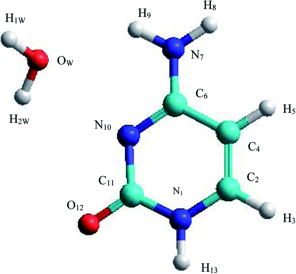 | ||
| Fig. 2 Structure and annotation of atoms in the C–W complex. | ||
All the reaction coordinates (RC) considered to carry out the SMD simulations for mechanisms studied can be expressed as:
| RC1a1 = d(OW − H9) − d(OW − H1W), |
| RC2a1 = d(H2W − N10) − d(H2W − OW), |
| RC1a2 = d(OW − C6), |
| RC2a2 = d(H9 − N7) − d(H9 − OW), |
| RC3a2 = θ(OW, H2W, C6, N7), |
| RC4a2 = θ(H1W, C6, N7, H8), |
| RC1a3 = d(C6 − N7), |
| RC2a3 = d(H1W − N7) − d(H1W − OW1), |
| RC1b1 = d(H1W − N7) − (H1W − OW), |
| RC2b1 = d(OW − C6), |
| RC3b1 = θ(OW, H1W, C6, H10), |
| RC4b1 = d(C6 − N7), |
| RC1b2 = d(H1W − N10) − d(H1W − OW). |
Two mechanisms were considered in this work depending whether it starts with a protonation on the imino nitrogen N10 or with the attack of the water molecule on the C6–N7 bond of the cytosine base:
• A-pathway: initially the oxygen OW and hydrogen H2W atoms of the water molecule attack the hydrogen atom H9 and the nitrogen atom N10 of the cytosine, respectively, in a concerted way via RC1a1 and RC2a1 reaction coordinates, forming an imine–oxo intermediate (I1a). In a second step, the water molecule attacks again the cytosine base but now the oxygen atom OW on the carbon atom C6 and the hydrogen atom H9 on the nitrogen atom N7, by means of RC1a2 and RC2a2 reaction coordinates, forming an amino–hydroxy–oxo intermediate (I2a). In this second step, torsions of –OH and –NH2 groups adopt the optimal conformation of the intermediate to perform the protonation in the next step, via the reaction coordinates RC3a2 and RC4a2. Finally, in the third step, the intermediate I2a converts to the uracil–ammonia (U–A) complex as a result of the break in the C6–N7 bond and the transfer of the hydroxyl hydrogen H2W to the nitrogen N7 atom, through RC1a3 and RC2a3 reaction coordinates. All these steps and structures are schematized in Fig. 3.
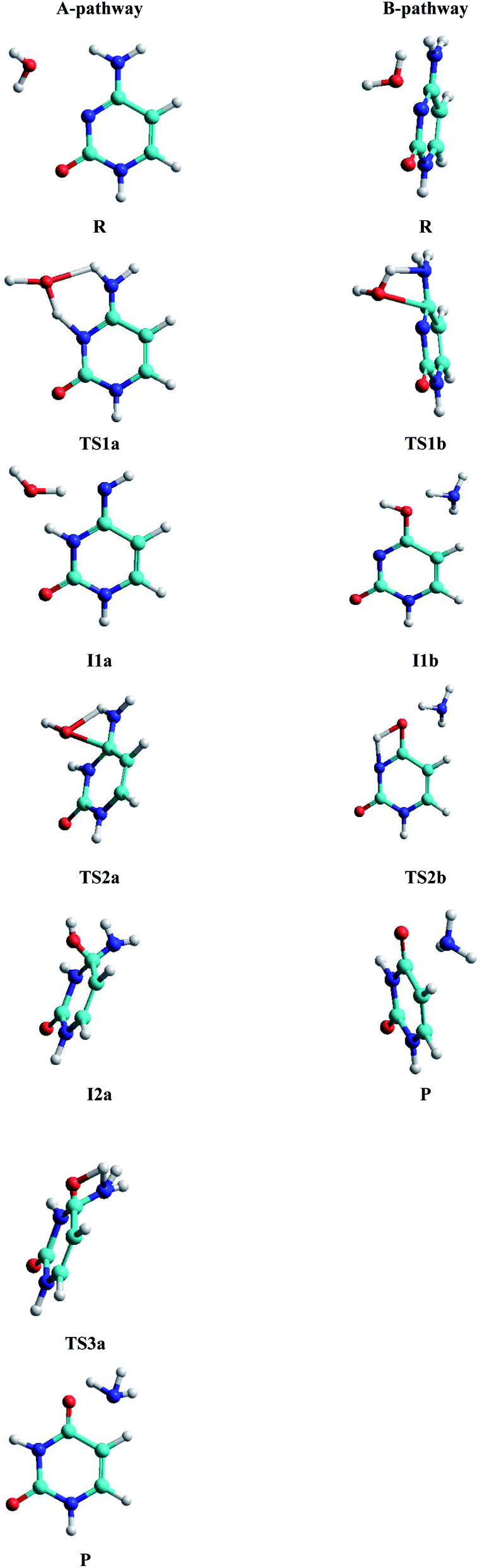 | ||
| Fig. 3 Stationary structures in both pathways. | ||
• B-pathway: initially the assistant water molecule is displaced from its planar position (θOw–C6–N10–C11 = 0°) to a more adequate perpendicular position (θOw–C6–N10–C11 = 90°) to attack the cytosine base on the C–N bond. Then, the OW and H1W atoms of the water molecule concertedly attack carbon C6 and nitrogen N7 atoms of the cytosine base, respectively, following RC1b1 and RC2b1 reaction coordinates. Simultaneously, the torsion of the –NH2 group is realized and the C6–N7 bond starts breaking to give the hydroxy–oxo intermediate (I1b) and the ammonia molecule, via RC3b1 and RC4b1 reaction coordinates. In a second step, the hydroxyl hydrogen H2W atom is transferred intramolecularly to nitrogen N10 atom, through the RC1b2 coordinate, to form the uracil base, the ammonia molecule moves away from the uracil base. These two steps and structures are also schematized in Fig. 3.
In the simulations of both mechanisms, the free movement of all solvent molecules, the assistant water molecule, and some of the atoms of the cytosine base (specifically, C6, N7, H8, H9 and N10 atoms) were allowed. The remaining atoms were fixed during simulations to avoid distorting of the cytosine base. Cartesian coordinates of stationary structures in each mechanism from SMD simulations are collated in Table S2 of the ESI.†
3.2. Structural and energies from electronic calculations
Analysis of the structural and energetic results for the cytosine deamination obtained from single point calculation using a PCM-M06-2X/6-311++G(d,p) level, taking the geometries of Almatarneh,40 gives the following observations:(a) Describing the A-pathway: in the TS1a state, the H2W atom is at 1.41 Å from the donor atom OW and at 1.13 Å from the acceptor atom N10 (with an angle of θOHN = 149.9°), whereas the H9 hydrogen is at 1.13 Å from the donor nitrogen and at 1.39 Å from the acceptor oxygen, forming a six-membered ring. The I1a intermediate has the hydrogen linked to the N10 nitrogen, dN10–H2W = 1.0 Å, forming an imine–oxo tautomer of the cytosine. In the second transition state TS2a, OW atom is at 1.76 Å from C6 carbon and the hydrogen at 1.26 Å from N7 nitrogen, forming a four-membered ring in a perpendicular plane to the cytosine ring. The second intermediate I2a shows a tetrahedral structure on carbon C6, forming a bond with the hydroxyl group at a distance dC6–OW = 1.46 Å, however, the orientation of the hydroxyl group –OH is not adequate to transfer the hydrogen H1W to the amino group –NH2, and therefore both groups perform rotations to reach the third transition state TS3a with the hydrogen H1W at 1.2 Å distance from nitrogen N7, whereas C6–N7 bond was extended to 1.6 Å.
(b) For the B-pathway case, TS1b transition state shows a has similar structure to the TS2a described above (except that the N10 atom is not linked to any hydrogen) and distances are dH1W–N7 = 1.09 Å, dH1W–OW = 1.46 Å, dOW–C6 = 1.92 Å, and dC6–N7 = 1.48 Å. The water oxygen is then linked to C6 carbon, dOW–C6 = 1.32 Å, in the hydroxyl–oxo intermediate Ilb, resulting in a uracil tautomer. Finally, in the second transition state TS2b, the hydroxyl hydrogen is at 1.35 Å from the oxygen donor and at 1.47 Å from the acceptor nitrogen, forming a four-membered ring in the same plane as the uracil ring.
(c) The free energies, including thermal corrections, obtained from quantum calculations with a continuous description of the surrounding medium (see Fig. 4 and Table S3 of the ESI†) have, in the A-pathway, a barrier of ΔG‡(TS1a) = 15.42 kcal mol−1 for the imine nitrogen protonation, another of ΔG‡(TS2a) = 50.39 kcal mol−1 for the attack of water on the CN double bond, and the last of ΔG‡(TS3a) = 46.75 kcal mol−1 for the hydroxyl hydrogen transfer to amine nitrogen N7, respect to the C–W complex energy considered as zero energy. The barriers in the B-pathway have values of ΔG‡(TS1b) = 55.88 kcal mol−1 for the tetrahedral intermediate formation and of ΔG‡(TS2b) = 31.50 kcal mol−1 for the hydroxyl hydrogen transfer to imine nitrogen N10. Therefore, we can say that the highest barrier in both mechanisms is obtained when atom OW attacked carbon C6 to form the tetrahedral structures on C6 atom. The greater stability of the U–A complex with respect to the C–W complex indicates the slight exothermic character of this deamination (ΔG = −3.58 kcal mol−1), whereas the higher barrier in the B-pathway makes this mechanism slower.
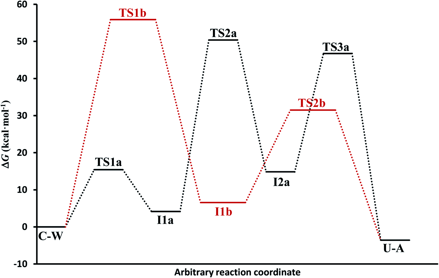 | ||
| Fig. 4 Electronic energy levels for A-pathway and B-pathway in solution phase. | ||
3.3. Energies from SMD simulations
Activation (ΔG‡) and reaction (ΔG) free energies for A- and B-pathways from the SMD simulations in solution and gas phase, together with the structure electronic results in gas phase of Almatarneh et al.,40 are presented in Table 1.| Mechanisms | Phase | ΔG‡a | ΔGb |
|---|---|---|---|
| a Activation energy (kcal mol−1) evaluated as ΔG‡ = G(transition state) − G(reactant).b Reaction energy (kcal mol−1) evaluated as ΔG = G(product, intermediate) − G(reactant).c In this work.d Electronic energies of Almatarneh et al.40 using a G3MP2 level.e This electronic energy does not correspond to the U–A conformation of our work. | |||
| A-pathway (1-step) | Solutionc | 32.28 | 10.73 |
| Gasc | 29.62 | 4.50 | |
| Gasd | 19.04 | 2.27 | |
| A-pathway (2-step) | Solutionc | 67.53 | 28.78 |
| Gasc | 60.10 | 18.54 | |
| Gasd | 53.82 | 13.66 | |
| A-pathway (3-step) | Solutionc | 62.74 | 7.41e |
| Gasc | 53.65 | −3.64 | |
| Gasd | 36.18 | −8.18e | |
| B-pathway (1-step) | Solutionc | 87.78 | 20.28 |
| Gasc | 73.32 | 7.85 | |
| Gasd | 63.89 | 2.25 | |
| B-pathway (2-step) | Solutionc | 54.85 | 4.53 |
| Gasc | 46.24 | 4.11 | |
| Gasd | 30.07 | −8.18e | |
In general, simulations in an aqueous medium for both cytosine deamination pathways describe energy profiles that are in agreement with those obtained from our structure electronic calculations (compare Fig. 4 and 5), although higher energies are observed in all stationary states making this process slower. The small energy difference for the U–A product according to the mechanism followed is due to the final reorientation of the ammonia molecule with respect to the uracil molecule and the different solvent structure around the solute in each case. That is, energy profiles with more energetic transition states and intermediates are obtained using SMD simulations in solution with respect to our simulations in the gas phase and with those electronic calculations realized by Almatarneh et al.40
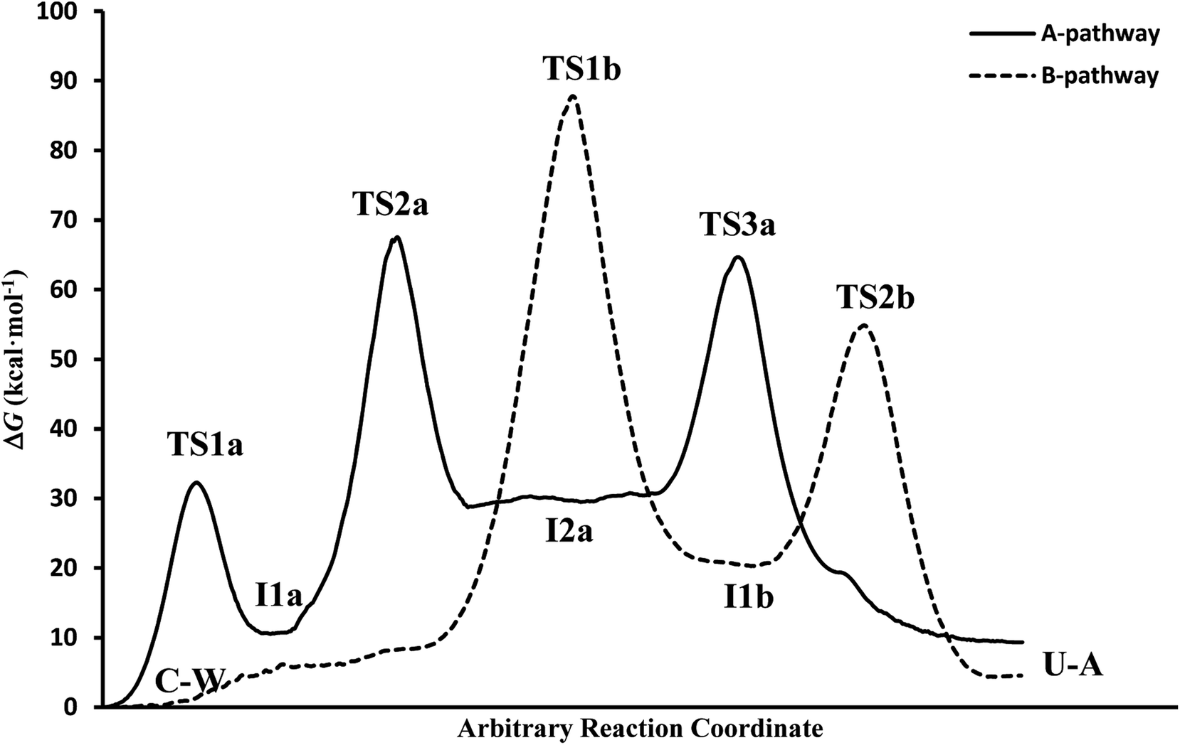 | ||
| Fig. 5 Free energy profiles from the SMD simulations. | ||
At this point, it is important to analyze why the activation barriers of the different mechanisms obtained by simulation are superior to those derived from our quantum studies. There are different causes that justify the observed discrepancies. First, the different levels of calculation used to treat the complex structures in the electronic calculations (PCM-M06-2X/6-311++G(d,p)) and in the QM-MM simulations (SCC-DFTB), which presents a different representation of the electron density. Another reason comes from the description at the molecular level of the solvent that can cause some molecule of the surrounding environment to compete with the assistant water molecule, making more difficult the transference and therefore a higher the activation barrier compared to our quantum studies, where a continuous description of the solvent is employed. Finally, the profile represents the energy at each step of the chosen reaction coordinate and showing the adaptation of the system to the current position of the fixed atoms of cysteine (partially restrained flexibility) and to the parameters used in the simulations, unlike the electronic calculation in which each stationary point is optimized.
It is also important to highlight why the activation barriers are higher in solution that in the gas phase using SMD simulations. The main cause that justifies this behavior is in water molecules that surrounded the C–W system, which can compete with the assistant water molecule and hinder the atoms transfer from one molecule to another. A second water molecule assisting the process avoid this effect and decrease the energies of the reaction profiles as we have verified in recent studies,70,71 where similar processes were assisted by several water molecules, mainly in those representative structures of transition states where it is possible that six-membered rings were formed which makes more stable stationary states.
In spite of the endergonic reaction energy, ΔG = 7.41 kcal mol−1, the high energy barriers show the difficulty in reverting U–A complex to the I2a intermediate and to the initial C–W complex. The activation energy for the determinant step is significantly different from the experimental value, showing that this reaction rarely occurs in a neutral medium and requires another type of catalyst or the presence of a second assistant molecule to decrease the barrier. However, A-pathway adequately describes the deamination mechanism of cytosine.
It is interesting to note that in A-pathway, the intermediate I1a represents a stable tautomer of the canonical cytosine and between the second and third step there are several conformational changes (torsions of the –OH and –NH2 groups) with indistinguishable barriers in SMD calculations (see energy profile between TS2a and TS3a). The final product U–A has a long lifetime of τU–A = 6.10 × 1027 s (calculated as τ = 1/k−3, being k−3 the reverse rate constant of the equilibrium I2a ⇆ U–A), indicating its possible participation in spontaneous mutation process. Besides, the deamination process was slow with a small rate constant of the determinant step of k2 = 1.80 × 10⁻³ s−1, evaluated as 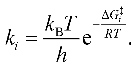
If we compare the energy profile with the one obtained in the gas phase (see values in Table 1), we see a similar behavior although all the structures are more energetic. The presence of discrete molecules of water can lead to some of them entering in competition with the assistant molecule, hindering the transfer processes. In turn, in profile gas phase, highlights the exergonic character (ΔG = −3.64 kcal mol−1) in better agreement with the one presented by Almatarneh et al.40 in a similar study. It should be also noted that the U–A product in solution has a configuration different from that of Almatarneh's work because in our simulation the ammonia molecule is away from the uracil base along the direction of the C6–N7 bond without seeking an optimum position that could be found in the O12–H13 zone by forming hydrogen bonds.
The overall reaction energy of ΔG = 4.53 kcal mol−1 indicates an endergonic process with difficulty in reverting to other previous structures since an initial barrier of 50.32 kcal mol−1 has to be overcome. The final U–A product has a long lifetime of 1.30 × 1024 s, indicating its possible participation in spontaneous mutation processes. Furthermore, the deamination process is slower in this pathway with a smaller rate constant of k1 = 2.50 × 10−52 s−1 for the determinant step.
Again the structures in solution turn out to be more energetic than those in the gas phase, highlighting the similarity of energy for the final specie U–A in both simulations.
N double bond in the I1a structure. The step that describes the proton transfer from the –OH to –NH2 group in the A-pathway is of similar energy as when the hydrogen is transferred to the –NH group in B-pathway. Likewise, the tautomeric intermediate of uracil I1b is more stable than the cytosine tautomer I1a since reverting to the initial C–W complex required more energy. Finally, the simulation of both pathways allows us to see the solvent structure around the C–W and U–A complexes, obtaining values of the global reaction energy that differ by less than 3 kcal mol−1.4. Conclusions
The cytosine deamination process in aqueous solution has been studied by applying SMD simulations. In between different mechanisms used, the simulation of A-pathway, where a proton transfer is made from the water molecule in the first step, is the most kinetically favorable. All transition state and intermediate structures have energies higher than those obtained from electronic calculations using a continuous solvent model and from the gas phase simulations. Better results can be obtained when it is considered more water molecules assisting the deamination process. The formation of the tetrahedral intermediate on C6 is the most energetic step in both mechanisms, while the transfer of the hydrogen of the hydroxyl group to the amino nitrogen N7 or imino nitrogen N10 are of similar energy. The stability of the U–A complex, with long lifetimes, indicates that uracil bases formed in this deamination reaction could participate in genetic mutation. Finally, we would like to emphasize the importance of performing SMD simulations to describe reaction mechanisms in nitrogenous bases at a molecular level, from which the evolution of the C–W ⇆ U–A process along the reaction coordinate can be studied and visualized.Conflicts of interest
There are no conflicts to declare.Acknowledgements
Alvaro Sabio Bernalte, student of the Chemistry degree, has collaborated in the realization of the calculations as a complement to his final degree project.References
- A. Warshel, Computer Modeling of Chemical Reactions in Enzymes and Solutions, Wiley & Sons, New York 1991 Search PubMed.
- ed. A. Müeller, H. Ratajczak, W. Junge and E. Diemann, Electron and Proton Transfer in Chemistry and Biology, Elsevier, Amsterdam, 1992 Search PubMed.
- ed. C. J. Cramer and D. G. Truhlar, Structure and Reactivity in Aqueous Solution: Characterization of Chemical and Biological Systems, American Chemical Society, Washington D.C, 1994 Search PubMed.
- P. Bała, P. Grochowski, B. Lesyng and J. A. McCammon, in Quantum Mechanical Simulation Methods for Studying Biological Systems, Springer-Verlag, Berlin Heidelberg, 1996, pp. 119–156 Search PubMed.
- ed. G. Náray-Szabó and A. Warshel, Computational Approaches to Biochemical Reactivity, Kluwer Academic Publishers, Dordrecht, 1997 Search PubMed.
- ed. O. Tapia and J. Bertrán, Solvent Effects and Chemical Reactivity, Springer, Netherlands, 2002 Search PubMed.
- ed. M. Ferrario, G. Ciccotti and K. Binder, Computer Simulations in Condensed Matter Systems: From Materials to Chemical Biology, vol. 1, Springer, Berlin, 2006 Search PubMed.
- J. C. Kotz, P. M. Treichel and J. R. Townsend, Chemistry and chemical reactivity, Brooks/Cole, Belmont, 2009, 8th edn Search PubMed.
- J. D. Watson and F. H. C. Crick, Cold Spring Harbor Symp. Quant. Biol., 1953, 18, 123–131 CrossRef CAS PubMed.
- J. P. Cerón-Carrasco, A. Requena, C. Michaux, E. A. Perpète and D. Jacquemin, J. Phys. Chem. A, 2009, 113, 7892–7898 CrossRef PubMed.
- J. P. Cerón-Carrasco, A. Requena, J. Zúñiga, C. Michaux, E. A. Perpète and D. Jacquemin, J. Phys. Chem. A, 2009, 113, 10549–10556 CrossRef PubMed.
- J. P. Cerón-Carrasco, A. Requena, E. A. Perpète, C. Michaux and D. Jacquemin D, Chem. Phys. Lett., 2009, 484, 64–68 CrossRef.
- O. O. Brovarets' and D. M. Hovorun, Biopolym. Cell, 2010, 26, 72–76 Search PubMed.
- O. O. Brovarets' and D. M. Hovorun, J. Biomol. Struct. Dyn., 2014, 32, 127–154 CrossRef PubMed.
- O. O. Brovarets' and D. M. Hovorun, J. Biomol. Struct. Dyn., 2014, 32, 1474–1499 CrossRef PubMed.
- O. O. Brovarets' and D. M. Hovorun, J. Biomol. Struct. Dyn., 2015, 33, 28–55 CrossRef PubMed.
- O. O. Brovarets' and D. M. Hovorun, J. Biomol. Struct. Dyn., 2015, 33, 925–945 CrossRef PubMed.
- D. Jacquemin, J. Zúñiga, A. Requena and J. P. Cerón-Carrasco, Acc. Chem. Res., 2014, 47, 2467–2474 CrossRef CAS PubMed.
- J. P. Cerón-Carrasco and D. Jacquemin, Phys. Chem. Chem. Phys., 2015, 17, 7754–7760 RSC.
- A. Broo and A. Holmén, J. Phys. Chem. A, 1997, 101, 3589–3600 CrossRef CAS.
- S. Morpurgo, M. Bossa and G. O. Morpurgo, Adv. Quantum Chem., 2000, 36, 169–183 CrossRef.
- L. A. Frederico, T. A. Kunkel and B. R. Shaw, Biochemistry, 1990, 29, 2532–2537 CrossRef CAS PubMed.
- J. Leszczyński, J. Phys. Chem., 1992, 96, 1649–1653 CrossRef.
- S. Miertuš, E. Scrocco and J. Tomasi, Chem. Phys., 1981, 55, 117–129 CrossRef.
- A. V. Marenich, C. J. Cramer and D. G. Truhlar, J. Phys. Chem. B, 2009, 113, 6378–6396 CrossRef CAS PubMed.
- C. J. Cramer and D. G. Truhlar, Chem. Rev., 1999, 99, 2161–2200 CrossRef CAS PubMed.
- B. J. Alder and T. E. Wainwright, J. Chem. Phys., 1959, 31, 459–466 CrossRef CAS.
- S. Izrailev, S. Stepaniants, B. Isralewitz, D. Kosztin, H. Lu, F. Molnar, W. Wriggers and K. Schulten, in Computational Molecular Dynamics, Challenges, Methods, Ideas, Vol. 4 of Lecture Notes in Computational Science and Engineering, ed. P. Deuflhard, J. Hermans, B. Leimkuhler, A. E. Mark, S. Reich and R. D. Skell, Springer-Verlag, Berlin, 1998, pp. 39–65 Search PubMed.
- B. Isralewitz, M. Gao and K. Schulten, Curr. Opin. Struct. Biol., 2001, 11, 224–230 CrossRef CAS PubMed.
- A. K. Chandra, M. T. Nguyen and T. Zeegers-Huyskens, J. Mol. Struct., 2000, 519, 1–11 CrossRef CAS.
- A. K. Chandra, D. Michalska, R. Wysokinsky and T. Zeegers-Huyskens, J. Phys. Chem. A, 2004, 108, 9593–9600 CrossRef CAS.
- M. Monajjemi, R. Ghiasi and A. Abedi, Theor. Inorg. Chem., 2005, 50, 435–441 CAS.
- J. V. Burda, J. Šponer, J. Leszczyński and P. Hobza, J. Phys. Chem. B, 1997, 101, 9670–9677 CrossRef CAS.
- J. Šponer, J. V. Burda, M. Sabat, J. Leszczyński and P. Hobza, J. Phys. Chem. A, 1998, 102, 5951–5957 CrossRef.
- A. Les, L. Adamowicz and R. J. Bartlett, J. Phys. Chem., 1989, 93, 4001–4005 CrossRef CAS.
- P. U. Civcir, J. Mol. Struct.: THEOCHEM, 2000, 532, 157–169 CrossRef CAS.
- I. R. Gould, D. V. S. Green, P. Young and I. H. Hillier, J. Org. Chem., 1992, 57, 4434–4437 CrossRef CAS.
- J. R. Sambrano, A. R. Souza, J. J. Queralt and J. Andrés, Chem. Phys. Lett., 2000, 317, 437–443 CrossRef CAS.
- J. E. Šponer, P. J. Sanz Miguel, L. Rodríguez-Santiago, A. Erxleben, M. Krumm, M. Sodupe, J. Šponer and B. Lippert, Angew. Chem., Int. Ed., 2004, 43, 5396–5399 CrossRef PubMed.
- M. H. Almatarneh, C. G. Flinn, R. A. Poirier and W. A. Sokalski, J. Phys. Chem. A, 2006, 110, 8227–8234 CrossRef CAS PubMed.
- V. Labet, A. Grand, C. Morell, J. Cadet and L. A. Eriksson, Theor. Chem. Acc., 2008, 120, 429–435 Search PubMed.
- V. Labet, C. Morell, A. Grand and A. Toro-Labbé, J. Phys. Chem. A, 2008, 112, 11487–11494 CrossRef CAS PubMed.
- X. Zhang, Y. Zhao, H. Yan, Z. Cao and Y. Mo, J. Comput. Chem., 2016, 37, 1163–1174 CrossRef CAS PubMed.
- Y. Zhao and D. G. Truhlar, Theor. Chem. Acc., 2008, 120, 215–241 Search PubMed.
- J. Gu, J. Wang, J. Leszczyński, Y. Xie and H. F. Schaefer III, Chem. Phys. Lett., 2008, 459, 164–166 CrossRef CAS.
- J. C. Hargis, H. F. Schaefer III, K. N. Houk and S. E. Wheeler, J. Phys. Chem. A, 2010, 114, 2038–2044 CrossRef CAS PubMed.
- C. Acosta-Silva, V. Branchadell, J. Bertrán and A. Oliva, J. Phys. Chem. B, 2010, 114, 10217–10227 CrossRef CAS PubMed.
- Y. Zhao and D. G. Truhlar, Chem. Phys. Lett., 2011, 502, 1–13 CrossRef CAS.
- J. Tomasi, B. Mennucci and R. Cammi, Chem. Rev., 2005, 105, 2999–3093 CrossRef CAS PubMed.
- M. J. Frisch, G. W. Trucks, H. B. Schlegel, G. E. Scuseria, M. A. Robb, J. R. Cheeseman, G. Scalmani, V. Barone, G. A. Petersson, H. Nakatsuji, X. Li, M. Caricato, A. Marenich, J. Bloino, B. G. Janesko, R. Gomperts, B. Mennucci, H. P. Hratchian, J. V. Ortiz, A. F. Izmaylov, J. L. Sonnenberg, D. Williams-Young, F. Ding, F. Lipparini, F. Egidi, J. Goings, B. Peng, A. Petrone, T. Henderson, D. Ranasinghe, V. G. Zakrzewski, J. Gao, N. Rega, G. Zheng, W. Liang, M. Hada, M. Ehara, K. Toyota, R. Fukuda, J. Hasegawa, M. Ishida, T. Nakajima, Y. Honda, O. Kitao, H. Nakai, T. Vreven, K. Throssell, J. A. Montgomery Jr, J. E. Peralta, F. Ogliaro, M. Bearpark, J. J. Heyd, E. Brothers, K. N. Kudin, V. N. Staroverov, T. Keith, R. Kobayashi, J. Normand, K. Raghavachari, A. Rendell, J. C. Burant, S. S. Iyengar, J. Tomasi, M. Cossi, J. M. Millam, M. Klene, C. Adamo, R. Cammi, J. W. Ochterski, R. L. Martin, K. Morokuma, O. Farkas, J. B. Foresman and D. J. Fox, Gaussian 09 (Revision A.1), Gaussian, Inc., Wallingford CT, 2009 Search PubMed.
- W. D. Cornell, P. Cieplak, C. I. Bayly, I. R. Gould, K. M. Merz Jr, D. M. Ferguson, D. C. Spellmeyer, T. Fox, J. M. Caldwell and P. A. Kollman, J. Am. Chem. Soc., 1995, 117, 5179–5197 CrossRef CAS.
- R. S. Mulliken, J. Chem. Phys., 1955, 23, 1833–1840 CrossRef CAS.
- W. D. Cornell, P. Cieplak, C. I. Bayly and P. A. Kollman, J. Am. Chem. Soc., 1993, 115, 9620–9631 CrossRef CAS.
- W. Damm, A. Frontera, J. Tirado-Rives and W. L. Jorgensen, J. Comput. Chem., 1997, 18, 1955–1970 CrossRef CAS.
- W. L. Jorgensen, D. S. Maxwell and J. Tirado-Rives, J. Am. Chem. Soc., 1996, 118, 11225–11236 CrossRef CAS.
- W. L. Jorgensen and J. Tirado-Rives, J. Am. Chem. Soc., 1988, 110, 1657–1666 CrossRef CAS PubMed.
- G. Kaminski, E. M. Duffy, T. Matsui and W. L. Jorgensen, J. Phys. Chem., 1994, 98, 13077–13082 CrossRef CAS.
- D. A. Case, T. A. Darden, T. E. Cheatham III, C. L. Simmerling, J. Wang, R. E. Duke, R. Luo, R. C. Walker, W. Zhang, K. M. Merz, B. Roberts, S. Hayik, A. Roitberg, G. Seabra, J. Swails, A. W. Götz, I. Kolossváry, K. F. Wong, F. Paesani, J. Vanicek, R. M. Wolf, J. Liu, X. Wu, S. R. Brozell, T. Steinbrecher, H. Gohlke, Q. Cai, X. Ye, J. Wang, M.-J. Hsieh, G. Cui, D. R. Roe, D. H. Mathews, M. G. Seetin, R. Salomon-Ferrer, C. Sagui, V. Babin, T. Luchko, S. Gusarov, A. Kovalenko, and P. A. Kollman, AMBER 12, University of California, San Francisco, 2012 Search PubMed.
- P. P. Ewald, Ann. Phys., 1921, 64, 253–287 CrossRef.
- C. Jarzynski, Phys. Rev. Lett., 1997, 78, 2690–2693 CrossRef CAS.
- T. Frauenheim, D. Porezag, M. Elstner, G. Jungnickel, J. Elsner, M. Haugk, A. Sieck and G. Seifert, Mater. Res. Soc. Symp. Proc., 1998, 491, 91–104 CrossRef CAS.
- M. Elstner, D. Porezag, G. Jungnickel, J. Elsner, M. Haugk, T. Frauenheim, S. Suhai and G. Seifert, Phys. Rev. B: Condens. Matter Mater. Phys., 1998, 58, 7260–7268 CrossRef CAS.
- G. M. Seabra, R. C. Walker, M. Elstner, D. A. Case and A. E. Roitberg, J. Phys. Chem. A, 2007, 111, 5655–5664 CrossRef PubMed.
- R. C. Walker, M. F. Crowley and D. A. Case, J. Comput. Chem., 2008, 29, 1019–1031 CrossRef CAS PubMed.
- M. Elstner, Theor. Chem. Acc., 2006, 116, 316–325 Search PubMed.
- S. Tolosa, N. Mora-Díez, A. Hidalgo and J. A. Sansón, RSC Adv., 2014, 4, 44757–44768 RSC.
- S. Tolosa, J. A. Sansón, A. Hidalgo and N. Mora-Díez, Theor. Chem. Acc., 2016, 135, 251 Search PubMed.
- S. Tolosa, J. P. Sánchez, J. A. Sansón and A. Hidalgo, J. Mol. Liq., 2017, 237, 81–88 CrossRef CAS.
- S. Tolosa, J. A. Sansón and A. Hidalgo, Int. J. Quantum Chem., 2017, 117(20), e25429 CrossRef.
- S. Tolosa, J. A. Sansón and A. Hidalgo, J. Mol. Liq., 2018, 251, 308–316 CrossRef CAS.
- S. Tolosa, J. A. Sansón and A. Hidalgo, J. Mol. Liq., 2018, 265, 487–495 CrossRef CAS.
Footnote |
| † Electronic supplementary information (ESI) available: Table S1 displays the Cartesian coordinates for initial structures of C–W complex in solution from the electronic structure calculation. Table S2 shows the Cartesian coordinates of the stationary structures from the SMD simulations. Table S3 collects enthalpies and free energies in gas and solution phase of the stationary structures. See DOI: 10.1039/c8ra07390b |
| This journal is © The Royal Society of Chemistry 2018 |