DOI:
10.1039/C8RA07258B
(Paper)
RSC Adv., 2018,
8, 39884-39892
Preparation and mechanism analysis of high performance ceramic membrane by spray coating
Received
31st August 2018
, Accepted 7th November 2018
First published on 29th November 2018
Abstract
A spray coating method was proposed to fabricate an α-Al2O3 micro-filtration membrane with excellent performance. It was observed that air gaps could form inside the support during the coating stage that effectively prevent membrane forming particles from penetrating into the support without an intermediate layer. Thus the pure water permeability of the membrane with average pore size of 0.13 μm and thickness of 25.46 μm could reach 2893 Lm−2 h−1 bar−1. The effects of firing conditions, membrane thickness and backwash or backpulse conditions on the pore size distribution of the membrane were investigated. Meanwhile the prepared membrane could sustain good filtration performance and mechanical integrity during backpulsing and backwashing processes under the transmembrane pressure (TMP) of 8 bar, which also exhibited a rejection rate of 98.8% for the carbon ink with an average particle size of 164 nm.
1. Introduction
Over the past few decades, ceramic membranes have been making rapid progress in applications such as bio-pharmaceuticals, food and beverage processing, environmental protection and water treatment.1–4 High chemical durability enables ceramic membranes to have advantages over organic membranes on account of the intrinsic properties of ceramic materials, such as excellent thermal stability,5 high resistance to chemical corrosion,6 high-pressure resistance,7,8 long life time and stability over a wide range of pH.9,10
However, the industrial application of ceramic membranes has been limited due to their complex preparation processes and high cost compared to polymeric membranes.11 For instance, an intermediate layer is commonly added between the membrane layer and support to prevent small membrane forming particles penetrating into the large pores of the support.12–14 Ceramic membranes can be fabricated using different methods, the most common manufacturing processes are dip coating,15 tape casting,16 phase inversion,17,18 and chemical vapour deposition.19 Besides some processing routes without processing an intermediate layer (so called “one step preparation” in our laboratory),20–22 spray coating may be another effective way to reduce particle penetration, and has been proved to be an appropriate method to fabricate macro-porous membranes,23 but its applicability in preparing micro-filtration membranes has rarely been investigated.
Due to the above reasons, micro-filtration membrane was prepared on the macro-porous plate alumina support by spray coating in this study. Ceramic suspension was obtained by dispersing α-Al2O3 powder in an aqueous solution containing polyvinyl alcohol (PVA), polyvinyl pyrrolidone (PVP), polyacrylic acid (PAA) and glycerin. Then the effects of firing conditions on the membrane morphology, pore size distribution, as well as the permeation and bonding strength were investigated.
2. Experiment
2.1 Materials
Commercially available α-Al2O3 powder (α-Al2O3, 99.99% purity, d50 = 0.52 μm, SHOWA Co., Ltd, Japan) was used as the main film-forming material. PVA (M.W. ∼31![[thin space (1/6-em)]](https://www.rsc.org/images/entities/char_2009.gif) 000, Shanghai Aladdin Biochemical Technology Co., Ltd., China) was applied as the binder and pore former, while PVP (K30, M.W.∼30
000, Shanghai Aladdin Biochemical Technology Co., Ltd., China) was applied as the binder and pore former, while PVP (K30, M.W.∼30![[thin space (1/6-em)]](https://www.rsc.org/images/entities/char_2009.gif) 000, Biochemical Reagent, Shanghai Yuanju Biological Technology Co., Ltd., China), PAA (Biochemical Reagent, Tianjin Danmao Biological Technology Co., Ltd, China) were utilized as dispersants. Macro-porous alumina plate supports with the size of 25 mm in diameter and 3 mm in thickness were prepared based on our earlier work.24 Capillary glass tubes with a diameter of 0.3 mm and a length of 100 mm (West China Center of Medical Sciences, Sichuan University Instrument Plant, Sichuan, China) were used to test capillary force effect under different conditions. NaOH (Biochemical Reagent, Tianjin Fucheng Biological Technology Co., Ltd, Tianjin, China) was used to adjust the pH of the slurry. Commercial carbon ink (Hero, jingxi stationery commodity, China) was used to test the filtration performance of the membrane. Deionized water was adopted in all preparation processes.
000, Biochemical Reagent, Shanghai Yuanju Biological Technology Co., Ltd., China), PAA (Biochemical Reagent, Tianjin Danmao Biological Technology Co., Ltd, China) were utilized as dispersants. Macro-porous alumina plate supports with the size of 25 mm in diameter and 3 mm in thickness were prepared based on our earlier work.24 Capillary glass tubes with a diameter of 0.3 mm and a length of 100 mm (West China Center of Medical Sciences, Sichuan University Instrument Plant, Sichuan, China) were used to test capillary force effect under different conditions. NaOH (Biochemical Reagent, Tianjin Fucheng Biological Technology Co., Ltd, Tianjin, China) was used to adjust the pH of the slurry. Commercial carbon ink (Hero, jingxi stationery commodity, China) was used to test the filtration performance of the membrane. Deionized water was adopted in all preparation processes.
2.2 Preparation of the α-Al2O3 micro-filtration membrane
Firstly, homogeneous suspension was obtained by dispersing 5 g of alumina powder into 50 g of 0.16 wt% PAA aqueous solution (the pH was adjusted to 11 by adding 1 mol L−1 NaOH), and ball-milled for 1 h at a rotation speed of 400 rpm. Then, 1.5 g PVA, 0.5 g PVP and 0.75 g glycerin were added to the suspension slowly, and deionized water was used to adjust the total mass to 100 g. The suspension was stirred in a magnetic stirrer for 2 h, further sprayed vertically onto the prepared macro-porous alumina supports with a diameter of 25 mm and a thickness of 3 mm. The spraying parameters were listed in Table 1. After spray coating process, the samples were naturally dried for 10 h and fired in a muffle furnace from room temperature to 600 °C at 2 °C min−1 and soaked for 1 h, followed by being heated at 10 °C min−1 to target temperature and soaked for different time (1 h, 2 h, 3 h, 4 h).
Table 1 Spraying
| Spraying parameters |
Pressure (bar) |
Distance (cm) |
Flow rate of slurry (g s−1) |
Time of each circle (s) |
Naturally dry time between circles (min) |
Gun model |
| Value |
2 |
80 |
1 |
5 |
1 |
SATA jet C (SATA GmbH & Co. KG, Germany) |
2.3 Characterizations
The thickness and morphology of membrane were observed by scanning electron microscope (SEM) (ZEISS EVO 18, Germany). To avoid unstable transient effects, the membrane was saturated with deionized water (18 MΩ), and permeation was tested by collecting the permeate by a mass flowmeter of OSMO Inspector (Poseidon, Convergence, Netherlands). Each sample's effective filtration area was estimated to be 2.72 × 10⁻⁴ m2. The pore size distribution was characterized according to American Society for Testing and Materials (ASTM) Publication F316-03(2011) by liquid-liquid displacement (LLDP) apparatus (PSMA-10, GaoQ Functional Materials, China). The bonding strength between the membrane and the support was tested by backwashing or backpulsing under the transmembrane pressure (TMP) of 8 bar (the details can be found in Section 3.5), and the influence of backwashing and backpulsing on the pore size distribution were also investigated. The retention test was performed at a TMP of 2 bar with an ink concentration of 200 mg L−1. The concentration of filtrate and retention solution was tested by spectrophotometer (Cary60, Agilent, USA).
3. Results and discussion
3.1 Spray coating method
As shown in Fig. 1, capillary glass tubes with a diameter of 0.3 mm and a length of 100 mm (West China Center of Medical Sciences, Sichuan University Instrument Plant, China) are used to prove the superiority of spray coating method to the traditional method in the aspect of reducing particles penetration. Obviously, the slurry penetration depth in tubes treated by spraying is less than that of the rightmost one which is slightly dipped into the slurry vertically.
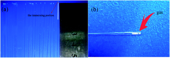 |
| | Fig. 1 (a): Slurry penetration phenomenon indicated by capillary tubes: the capillary tube located at the rightmost was vertically inserted into the slurry shallowly until the liquid level did not change. The others were bundled together, and the slurry was sprayed to their end faces vertically until the liquid level did not change; (b) enlarged image of the third tube from the left. | |
In fact, when the first droplet of the slurry is sprayed onto the support, it is sucked into the support by capillary force and then a small column of liquid forms inside the capillary pore. Before another droplet is sucked into the same pore, there is some air transport inside the pore. Thus an air gap forms between the two liquid columns. As illustrated in Fig. 2, the largest difference between spray coating and dip coating is that spray coating will make air captured between two penetrated slurry columns. So, the capillary force may not act on the suspension continuously, and the particles penetrate into the supports intermittently. Air will exist among the slurry columns in the capillaries of support and raise the resistance against capillary force. Hence, most of the slurry stays at the top layer of the support rather than being sucked into deeper site.
 |
| | Fig. 2 Schematic diagram of slurry penetration process of spray coating method (a) first droplet of the slurry sprayed onto the end face of capillary tube; (b) subsequent slurry droplet sprayed onto the end face of capillary tube. | |
3.2 Morphology of membranes
Fig. 3 shows the cross sectional morphology of the α-Al2O3 micro-filtration membrane prepared by spray coating method. It indicates that the membrane forming particles has only penetrated into the support slightly. Fig. 4 shows the membranes sintered at different temperatures for 2 h. No conspicuous changes occur in the grain sizes of membranes fired below 1300 °C (see Fig. 4a and b). When the temperature is above 1350 °C, the alumina grains will grow obviously. The average pore size of the membrane also enlarges to some extent (see Fig. 9), which accorded with the results reported by other researchers.25 When the firing temperature reaches 1400 °C, the grain size is about 3 μm. The shrinkage stress of the membrane layer causes by sintering is strong enough to tear the membrane apart to form some cracks or bigger pores on the surface (see Fig. 4e).
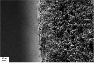 |
| | Fig. 3 Cross-section morphology of the α-Al2O3 micro-filtration membrane prepared by spray coating. | |
 |
| | Fig. 4 Surface morphology of the membranes fabricated at different sintering temperatures (soaked for 2 h): (a) 1250 °C; (b) 1300 °C; (c) 1350 °C; (d) 1400 °C; (e) 1450 °C. | |
Fig. 5 illustrates the influence of soaking time on the grain size when the membrane is fired at 1300 °C. Certain soaking time will give the membrane forming particles enough time to wriggle and adjust their position (see Fig. 5a and b). The grain size grows obviously when the membranes are soaked for more than 3 h (see Fig. 5c and d).
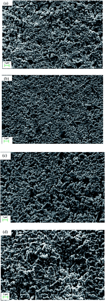 |
| | Fig. 5 Surface morphology of the membranes prepared at 1300 °C and soaked for different time: (a) 1 h; (b) 2 h; (c) 3 h; (d) 4 h. | |
3.3 Pore size distribution
Fig. 6 shows the pore size distributions of the membranes with different thickness. As shown in Fig. 6, the pore size distribution narrows down with the increment of membrane thickness. When the thickness increases from 15.00 μm to 25.46 μm, the largest pore size decreases from 1.08 μm to 0.17 μm but the average and most frequent pore size do not change too much, indicating that the pore size distribution and membrane performance mainly depends on the thickness. When the membrane is thicker than 25.46 μm, the pore size distribution is stabilized in a narrow range. It is deduced that when the membrane is thicker than 25.46 μm, a crack-free membrane will form. And when the membrane is not thick enough, some of the support may not be covered, that cause some big hole. The further increment of thickness only augments the filtering resistance rather than narrow the pore size distribution. Fig. 7 shows the pore size distribution of the 25.46 μm-thick membrane. As shown, the pore size distribution is narrow with a most frequent pore size of 0.125 μm.
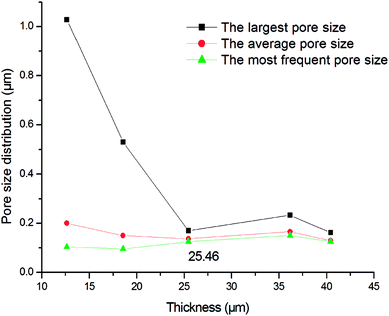 |
| | Fig. 6 Pore size distribution of the membranes with different thickness (fired at 1300 °C for 2 h). | |
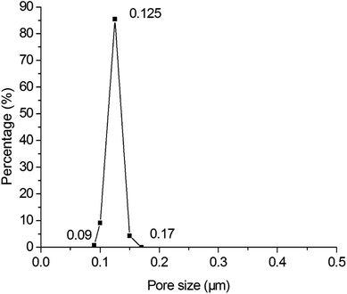 |
| | Fig. 7 Pore size distribution of the membrane prepared by spray coating with a thickness of 25.46 μm (fired at 1300 °C for 2 h). | |
Fig. 8 shows the pore size distribution with the largest pore size and most frequent pore size of the membranes fabricated at different firing temperatures. Some big pores generate in membrane layer when it is fired at 1250 °C (see Fig. 8a). This might be because of insufficient sintering of some membrane forming particles. The pore size distribution becomes narrow as the firing temperature increases from 1250 °C to 1300 °C (see Fig. 8a and b). When the firing temperature increases further (see Fig. 8c–e), the pore size distribution gets wider, which might result from the growth of grain size. Fig. 9 exhibits the relation between the average pore size of the membrane and the firing temperature. When the firing temperature elevates from 1250 °C to 1300 °C, the average pore size becomes smaller from 0.14 μm to 0.13 μm. It is partly because the elevation of firing temperature results in the elimination of large pores. When the sintering temperature increases from 1300 °C to 1450 °C, the average pore size increases from 0.13 μm to 0.38 μm. These may be attributed to the growth of grains leading to the formation of large pores when the membranes are fired at higher temperature.
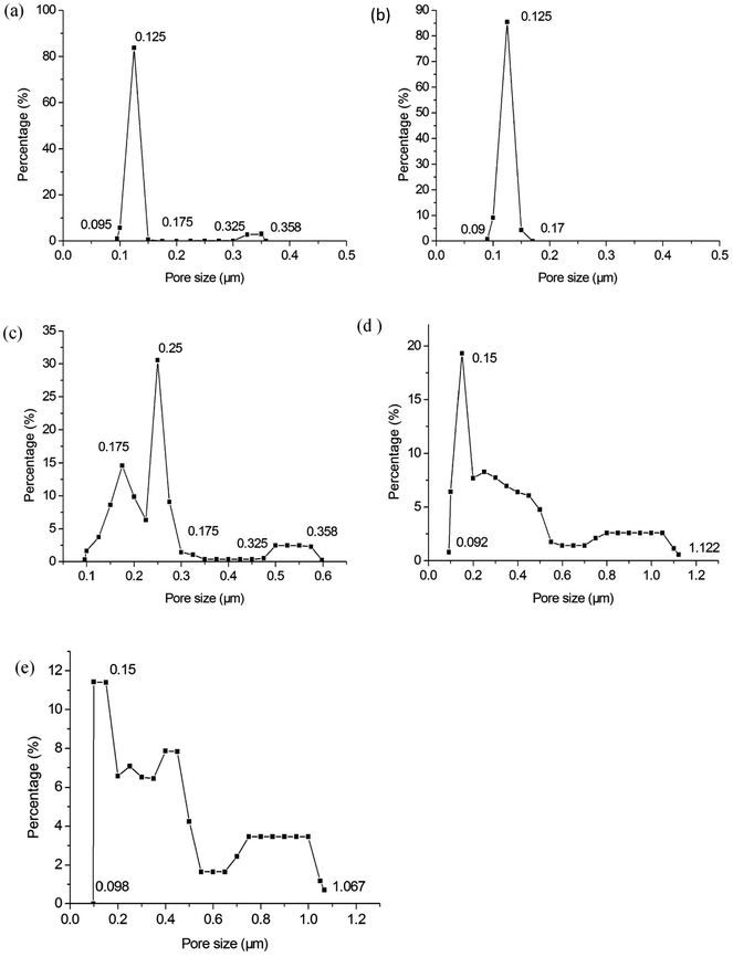 |
| | Fig. 8 Pore size distribution of the membranes fabricated at different firing temperatures (soaked for 2 h): (a) 1250 °C; (b) 1300 °C; (c) 1350 °C; (d) 1400 °C; (e) 1450 °C. | |
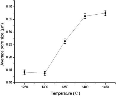 |
| | Fig. 9 The relation between the average pore size of the membrane and sintering temperature. | |
Fig. 10 illustrates the influence of soaking time on the pore size distribution. When the soaking time is 1 h (see Fig. 10a), there are large pores. It indicates 1 h is not adequate soaking time to sinter membranes sufficiently. When the soaking time reaches 2 h (see Fig. 10b), the large pores vanish entirely. They reappear with the soaking time of 3 h but the size is very close to the most frequent pore size (see Fig. 10c). The large pores grow further as the soaking time increases (see Fig. 10d). This can be attributed to the formation of big pores under the oversintering condition. This is corresponding to the relation between membrane forming particle size and soaking time.
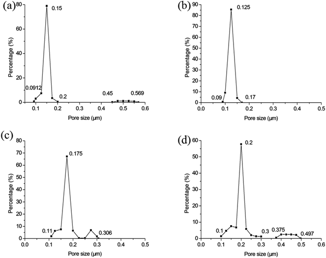 |
| | Fig. 10 The influence of soaking time on the pore size distribution of membrane (fires at 1300 °C): (a) 1 h; (b) 2 h; (c) 3 h; (d) 4 h. | |
3.4 Permeability of membranes
The water permeability of the membrane prepared by spray coating for 40 s and sintering at 1300 °C for 2 h is 2893 Lm−2 h−1 bar−1. Table 2 lists the permeability of micro-filtration membranes in this work and previous research. The average pore sizes of these membranes are at the same magnitude (0.1–0.5 μm). The results show that the permeability of the membrane in this work is much higher than that in other reports. This may result from reduction of infiltration of membrane forming particles.
Table 2 Water permeability of the membranes in this work and other research
| Membrane category |
Average pore size (μm) |
Thickness (μm) |
Water permeability (Lm−2 h−1 bar−1) |
Reference |
| α-Al2O3 |
0.13 |
25.46 |
2893 |
This work |
| α-Al2O3 |
0.27 |
15.6 |
332 |
Qin et al.22 |
| α-Al2O3 |
0.76 |
|
1930 |
Shi et al.26 |
| α-Al2O3 |
0.24 |
10 |
1410 |
Qin et al.27 |
3.5 Bonding strength of membranes
Backwash is commonly used to remove the fouling deposits in ultra-filtration and micro-filtration.8,28,29 Backpulse is used to test the bonding strength between membrane layers and supports.30 The as-prepared samples are characterized under different testing conditions (as shown in Table 3) to measure the bonding strength between membrane layers and porous supports. Comparison is performed on the pore size distribution of the membranes before and after backwash or backpulse process. Fig. 11 shows that the pore size distribution of each sample do not change much after performing backwash or backpulse, indicating the strong bonding strength between the micro-porous membrane and the macro-porous support, as well as excellent mechanical stability.
Table 3 Backwash or backpulse plans of the samples
| Condition sample |
TMP (bar) |
Backwash/backpulse |
Holding time of each circle (s) |
Circle times |
Total time (s) |
| A |
8 |
Backwash |
|
|
1000 |
| B |
8 |
Backpulse |
10 |
100 |
1000 |
| C |
8 |
Backpulse |
5 |
200 |
1000 |
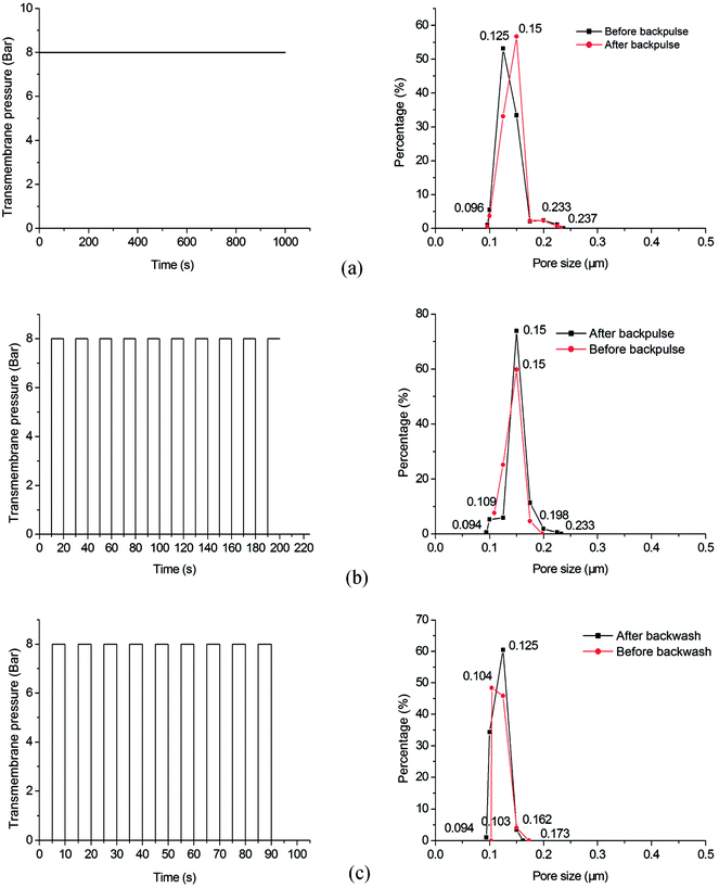 |
| | Fig. 11 Pore size distribution of the samples before and after backwash or backpulse: (a) sample A; (b) sample B; (c) sample C. | |
3.6 Filtration performance of membranes
To further characterize the separation performance of the prepared membrane, we employed a commercial carbon ink for filtration. For this ink, the average particle size was tested as 164 nm (as shown in the small graph of Fig. 12). The retention test was performed at a TMP of 2 bar. After 120 min of filtration, the rejection rate reaches about 98.8%. The change of water permeability is shown in Fig. 12, the water permeability decreases rapidly, and then is stable at about 180 Lm−2 h−1 bar−1.
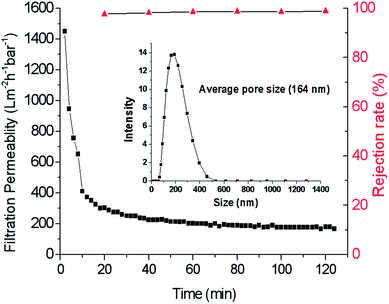 |
| | Fig. 12 Filtration permeability and retention rate changed with operation time and the particle size of carbon ink. | |
4. Conclusions
Spray coating is an ideal method to prepare ceramic membrane without intermediate layer due to its ability to reduce the penetration of membrane forming particles into the support. It is easy for spray coating to capture air in the support capillary pores and form air gaps between slurry columns, so the support pores are infiltrated intermittently by suspension in the spray coating method rather than continuously in the dip coating method which leads to less particle penetration and no intermediate layer. Therefore the ceramic membranes prepared by spray coating have narrow pore size distribution and high permeability. After optimizing the process, an α-Al2O3 micro-filtration membrane with an average pore size of 0.13 μm was prepared, showing excellent bonding strength, good rejection rate of 98.8% to the carbon ink with an average particle size of 164 nm, and a pure water permeability of 2893 Lm−2 h−1 bar−1 which is significantly higher than that of the alumina membranes prepared previously by the conventional techniques.
Conflicts of interest
There are no conflicts to declare.
Acknowledgements
This work was financially supported by the National Natural Science Foundation of China (Grant No. 51472092 and Grant No. 51702100) and Applied Science and Technology R&D Special Project of Guangdong Province, China (Grant No. 2016B090932001).
References
- J. Song, et al., Does pre-ozonation or in situ ozonation really mitigate the protein-based ceramic membrane fouling in the integrated process of ozonation coupled with ceramic membrane filtration?, J. Membr. Sci., 2018, 548, 254–262 CrossRef CAS.
- Y. Jeong, et al., Evaluating the feasibility of pyrophyllite-based ceramic membranes for treating domestic wastewater in anaerobic ceramic membrane bioreactors, Chem. Eng. J., 2017, 328, 567–573 CrossRef CAS.
- C. Ko, et al., Performance of ceramic membrane in vacuum membrane distillation and in vacuum membrane crystallization, Desalination, 2018, 440, 48–58 CrossRef CAS.
- S. M. Samaei, S. Gato-Trinidad and A. Altaee, The application of pressure-driven ceramic membrane technology for the treatment of industrial wastewaters – a review, Sep. Purif. Technol., 2018, 200, 198–220 CrossRef CAS.
- Y. S. Lin, K. J. de Vries and A. Burggraaf, Thermal stability and its improvement of the alumina membrane top-layers prepared by sol-gel methods, J. Mater. Sci., 1991, 26(3), 715–720 CrossRef CAS.
- Y. H. Wang, et al., Titania membrane preparation with chemical stability for very hash environments applications, J. Membr. Sci., 2006, 280(1–2), 261–269 CAS.
- H. Chang, et al., Hydraulic backwashing for low-pressure membranes in drinking water treatment: a review, J. Membr. Sci., 2017, 540, 362–380 CrossRef CAS.
- H. Chang, et al., Role of backwash water composition in alleviating ultrafiltration membrane fouling by sodium alginate and the effectiveness of salt backwashing, J. Membr. Sci., 2016, 499, 429–441 CrossRef CAS.
- M. Dalwani, et al., A method for characterizing membranes during nanofiltration at extreme pH, J. Membr. Sci., 2010, 363(1–2), 188–194 CrossRef CAS.
- B. Elyassi, M. Sahimi and T. T. Tsotsis, A novel sacrificial interlayer-based method for the preparation of silicon carbide membranes, J. Membr. Sci., 2008, 316(1–2), 73–79 CrossRef CAS.
- S. Khemakhem, A. Larbot and R. Ben Amar, New ceramic microfiltration membranes from Tunisian natural materials: application for the cuttlefish effluents treatment, Ceram. Int., 2009, 35(1), 55–61 CrossRef CAS.
- Y. Dong, et al., Cost-effective tubular cordierite micro-filtration membranes processed by co-sintering, J. Alloys Compd., 2009, 477(1–2), L35–L40 CrossRef CAS.
- D. Zou, et al., One-step preparation of high-performance bilayer α-alumina ultrafiltration membranes via co-sintering process, J. Membr. Sci., 2017, 524, 141–150 CrossRef CAS.
- J. Feng, et al., The effect of membrane thickness on the co-sintering process of bi-layer ZrO2/Al2O3 membrane, J. Membr. Sci., 2007, 305(1–2), 20–26 CAS.
- H. Guo, et al., Fabrication and characterization of TiO2/ZrO2 ceramic membranes for nanofiltration, Microporous Mesoporous Mater., 2018, 260, 125–131 CrossRef CAS.
- E. C. Hammel, O. L. R. Ighodaro and O. I. Okoli, Processing and properties of advanced porous ceramics: an application based review, Ceram. Int., 2014, 40(10), 15351–15370 CrossRef CAS.
- T. Young and L. Chen, Pore formation mechanism of membranes from phase inversion process, Desalination, 1995, 103(3), 233–247 CrossRef CAS.
- L. Li, et al., A low-cost alumina-mullite composite hollow fiber ceramic membrane fabricated via phase-inversion and sintering method, J. Eur. Ceram. Soc., 2016, 36(8), 2057–2066 CrossRef CAS.
- H. H. Han, et al., Gas permeation properties and preparation of porous ceramic membrane by CVD method using siloxane compounds, J. Membr. Sci., 2013, 431, 72–78 CrossRef CAS.
- X. Yin, et al., A preparation method for the highly permeable ceramic microfiltration membrane – precursor film firing method, RSC Adv., 2018, 8(6), 296–2914 RSC.
- Y. Liu, et al., Freeze-casting of alumina ultra-filtration membranes with good performance for anionic dye separation, Ceram. Int., 2018, 44(10), 11901–11904 CrossRef CAS.
- W. Qin, et al., One-step coating and characterization of α-Al2O3 microfiltration membrane, J. Membr. Sci., 2015, 490, 160–168 CrossRef CAS.
- W. Wei, et al., Preparation of non-oxide SiC membrane for gas purification by spray coating, J. Membr. Sci., 2017, 540, 381–390 CrossRef CAS.
- W. Qin, et al., Preparation and properties of high-purity porous alumina support at low sintering temperature, Ceram. Int., 2014, 40(8), 13741–13746 CrossRef CAS.
- Y. DONG, et al., Fabrication and characterization of low cost tubular mineral-based ceramic membranes for micro-filtration from natural zeolite, J. Membr. Sci., 2006, 281(1–2), 592–599 CrossRef CAS.
- Z. Shi, et al., Preparation and characterization of α-Al2O3 hollow fiber membranes with four-channel configuration, Ceram. Int., 2015, 41(1), 1333–1339 CrossRef CAS.
- W. Qin, C. Peng and J. Wu, A sacrificial-interlayer technique for single-step coating preparation of highly permeable alumina membrane, Ceram. Int., 2017, 43(1), 901–904 CrossRef CAS.
- K. Katsoufidou, S. Yiantsios and A. Karabelas, A study of ultrafiltration membrane fouling by humic acids and flux recovery by backwashing: Experiments and modeling, J. Membr. Sci., 2005, 266(1–2), 40–50 CrossRef CAS.
- E. Akhondi, F. Wicaksana and A. G. Fane, Evaluation of fouling deposition, fouling reversibility and energy consumption of submerged hollow fiber membrane systems with periodic backwash, J. Membr. Sci., 2014, 452, 319–331 CrossRef CAS.
- J. Feng, et al., Co-sintering synthesis of tubular bilayer α-alumina membrane, J. Membr. Sci., 2007, 288(1–2), 20–27 CAS.
|
| This journal is © The Royal Society of Chemistry 2018 |
Click here to see how this site uses Cookies. View our privacy policy here.  Open Access Article
 *
*
![[thin space (1/6-em)]](https://www.rsc.org/images/entities/char_2009.gif) 000, Shanghai Aladdin Biochemical Technology Co., Ltd., China) was applied as the binder and pore former, while PVP (K30, M.W.∼30
000, Shanghai Aladdin Biochemical Technology Co., Ltd., China) was applied as the binder and pore former, while PVP (K30, M.W.∼30![[thin space (1/6-em)]](https://www.rsc.org/images/entities/char_2009.gif) 000, Biochemical Reagent, Shanghai Yuanju Biological Technology Co., Ltd., China), PAA (Biochemical Reagent, Tianjin Danmao Biological Technology Co., Ltd, China) were utilized as dispersants. Macro-porous alumina plate supports with the size of 25 mm in diameter and 3 mm in thickness were prepared based on our earlier work.24 Capillary glass tubes with a diameter of 0.3 mm and a length of 100 mm (West China Center of Medical Sciences, Sichuan University Instrument Plant, Sichuan, China) were used to test capillary force effect under different conditions. NaOH (Biochemical Reagent, Tianjin Fucheng Biological Technology Co., Ltd, Tianjin, China) was used to adjust the pH of the slurry. Commercial carbon ink (Hero, jingxi stationery commodity, China) was used to test the filtration performance of the membrane. Deionized water was adopted in all preparation processes.
000, Biochemical Reagent, Shanghai Yuanju Biological Technology Co., Ltd., China), PAA (Biochemical Reagent, Tianjin Danmao Biological Technology Co., Ltd, China) were utilized as dispersants. Macro-porous alumina plate supports with the size of 25 mm in diameter and 3 mm in thickness were prepared based on our earlier work.24 Capillary glass tubes with a diameter of 0.3 mm and a length of 100 mm (West China Center of Medical Sciences, Sichuan University Instrument Plant, Sichuan, China) were used to test capillary force effect under different conditions. NaOH (Biochemical Reagent, Tianjin Fucheng Biological Technology Co., Ltd, Tianjin, China) was used to adjust the pH of the slurry. Commercial carbon ink (Hero, jingxi stationery commodity, China) was used to test the filtration performance of the membrane. Deionized water was adopted in all preparation processes.


