DOI:
10.1039/C8RA07207H
(Paper)
RSC Adv., 2018,
8, 36453-36458
The relationship between the laser damaged threshold and step velocity in different supersaturation regions
Received
29th August 2018
, Accepted 2nd October 2018
First published on 26th October 2018
Abstract
The laser damaged threshold (LDT) of potassium dihydrogen phosphate (KDP) crystals grown at different supersaturation points were investigated using a Nd:YAG nanosecond laser. The growth rate was measured by a laser polarization interference system. Combining the step slopes, the dependence of v–(σ) was obtained. It is interesting that the dependence of LDT-(σ) can also be divided into three areas and shows a similar dependence to that of v–(σ). The LDT reduces rapidly at the transition supersaturation area, and has the lowest value at σ = 0.07. In different supersaturation regions, the micro morphology of the KDP crystals was observed using an atomic force microscope. The nature of the step movement and bunching together of steps may contribute to the dependence of LDT-(σ).
1. Introduction
Potassium dihydrogen phosphate (KDP) crystals are widely used in lasers, electro-optical modulators, and other applications due to their excellent electro-optical and nonlinear optical properties. They are also the preferred and only laser frequency and switching materials currently used in high-power inertial confinement fusion (ICF) laser systems.1–3 In recent years, this application has made KDP crystals a hot topic in the area of artificial crystals. The laser damaged threshold (LDT) is the main performance index in high-power laser systems.
Many studies have suggested that laser damage is related to inorganic and organic impurities in the crystal growth solution.4–9 Liu et al.10 measured the laser induced damage thresholds of z cut and triple cut samples of DKDP (potassium dideuterium phosphate) crystals with different deuterium degrees using a 1-on-1 test at 355 nm. Rajesh's studies11 have shown that AKDP crystals (mixed crystals of ADP and KDP) are stable under lasers compared to other crystals. ADP (ammonium dihydrogen phosphate) and KDP crystals have been found to withstand up to 45 and 30 mJ for 30 s, respectively, whereas mixed crystal samples can withstand slightly less than 65 mJ. Dolzhenkova et al.12 tested the average values of the laser-induced damage threshold in pure and L-arginine-doped crystals for pyramidal and prismatic growth sectors measured in the laser irradiation directions [001] and [100]. It was thought that the laser-induced damage was due to the different conditions that brought about the formation of cracks in the crystal, caused by concentrated loads and laser pulses. The growth conditions, metal complex, and inclusions also have an effect on the LDT of crystals.13–15 However, the deep mechanism of laser damage in KDP crystals is unclear. The development of atomic force microscopy (AFM) has enabled the exploration of crystal growth at the atomic scale. The aim of this work is to study the effect of step evolution on the LDT of KDP crystals. The growth rate and step micro morphology of crystal surfaces at different supersaturation points were investigated.
2. Experiments
2.1 Crystal growth
KDP crystals were grown using a “point seed” rapid growth technique.16 Aqueous solutions were prepared using high purity KH2PO4 (Merck Co., Germany, with Fe3+, Cr3+ and Al3+ amounts of less than 1 ppm) and de-ionized water according to its solubility curve17 in a standard 1000 ml glass crystallizer.| | |
S = 6.02 × 10⁻³ × T2 + 0.208 × T + 15.9 (g KDP/100 g H2O)
| (1) |
where S is the solubility and T is the saturation temperature of the solution. In this experiment, the saturation temperature was around 45 °C. The solutions were heated at 80 °C for 24 h after being filtered through a 0.22 μm membrane. Crystals were grown on frames with a rotation speed of 77 rpm in “forward-stop-backward” mode. The experiments were carried out in a water bath, the temperature of which was controlled by a Shimada FP21 automatic temperature apparatus with an accuracy of ±0.01 °C. The supersaturation was calculated using the following equation:17where σ is the supersaturation, C is the actual concentration and C0 is the equilibrium saturation concentration at the experimental temperature, which can be calculated using the empirical equation:18| | |
C0 = 10.68 + 0.3616T ± 0.04 (g KDP per 100 g solution)
| (3) |
It should be pointed out that the seed crystals were z-cut with dimensions of 5 mm when prepared for the AFM tests. The crystals were grown at a set supersaturation after recovery under a temperature of 0.5 °C, lower than the saturation temperature, for several hours. After the crystals were grown to the required size, they were removed from the solution and transferred into CHCl3. The organic solvent CHCl3 eliminated the mother liquor from the crystal surface and protected it during the growth steps. Then, the crystals were allowed to cool naturally to room temperature.
2.2 Real-time measurement of the growth rate
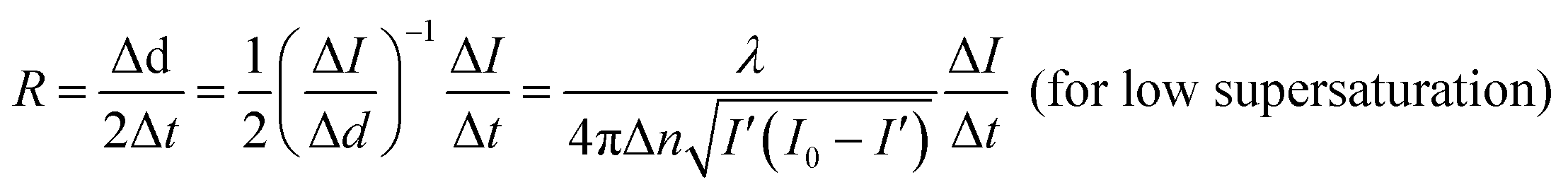
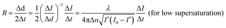
The growth rate of the (100) face of KDP crystals was measured using a laser polarization interference system,19 employing a laser beam with a wavelength of 473 nm. The crystals, of good optical quality with no obvious macroscopic defects, were prepared beforehand and put into a solution with a temperature 1.5 °C above the saturation point. The crystals were adjusted to ensure that the laser passed vertically through the (100) face. The solution cooling rate used was 3 °C h−1. The growth rate was calculated in terms of the relationship between the laser intensity and the crystal thickness:19| |
 | (4) |
| | |
R = λ/2ΔnΔt (for high supersaturation)
| (5) |
where R is the growth rate, d is the thickness of the crystal, λ is the laser wavelength, Δn is the crystal birefringence, I0 is the light intensity entering the crystal at moment t, I′ is the light intensity leaving the crystal at moment t, and I is the relative light intensity, calculated from I = I0/I′.
2.3 Micro morphology at different supersaturation points
The micro morphology of the crystals was observed using an atomic force microscope (AFM), a commercial Nanoscope IIIa MultiMode and Dimension Icon instruments. The crystals were adjusted to keep the observed surface horizontal before testing. The surface micromorphology on the (100) faces of the crystals was studied under ambient pressure at room temperature in Contact or ScanAsyst modes. The influence of the scanning itself on the original morphology was ignored.
2.4 Measurement of the laser damage threshold (LDT)
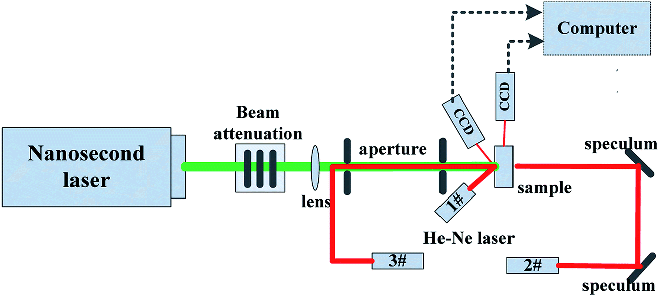
The laser damage threshold (LDT) of the samples was investigated using a fundamental wavelength of λ = 1064 nm by a Nd:YAG nanosecond laser, operating in 1-on-1 mode with a pulse duration of 8 ns, and a repetition rate of 1 Hz. The laser spot area was about 0.24 mm2. A diagram of the experimental device setup is shown in Fig. 1. The measurements were carried out on 10 × 10 × 15 mm3 (X × Y × Z) samples, which were cut from crystal prismatic sectors and the faces perpendicular to the laser were polished. The pulse was focused into the Z-cut KDP samples by a 50 cm lens.
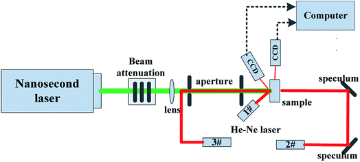 |
| | Fig. 1 A diagram of the experimental device setup. | |
3. Results
3.1 Step velocity versus the supersaturation
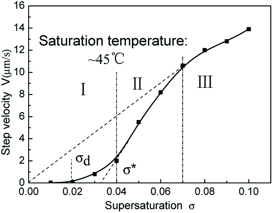
According to the theory of BCF (Burton–Cabrora–Frank), there is a geometrical relationship between the normal direction growth rate R and the step tangential speed v:17where p is the slope of the steps. Combining the slopes that were previously observed by AFM and the growth rate R, measured by the laser polarization interference system, the tangential speed v versus the supersaturation were obtained, and are shown in Fig. 2. It can be seen that the curve of v–(σ) can be divided into three areas. In area I, the supersaturation is low, the step velocity is slow and increases gradually after a “dead zone” σd, where no growth occurs. In area II, the supersaturation is above the linear region σ* and the step velocity rises rapidly, approaching linearity. In area III, the dependence v–(σ) becomes a straight line that passes through the origin at high supersaturation, which is similar to the results of the research by Rashkovich.20 The critical supersaturation σ′ was about 0.07 in this experiment. Referring to Land's experimental methods,21 both the two critical supersaturation regions, the dead zone σd and linear region σ*, were found to be around 0.0194 and 0.033, respectively.
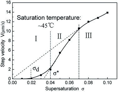 |
| | Fig. 2 Dependence of the step velocity of the (100) face on the supersaturation at around 45 °C. | |
3.2 Micro morphology in different supersaturation regions
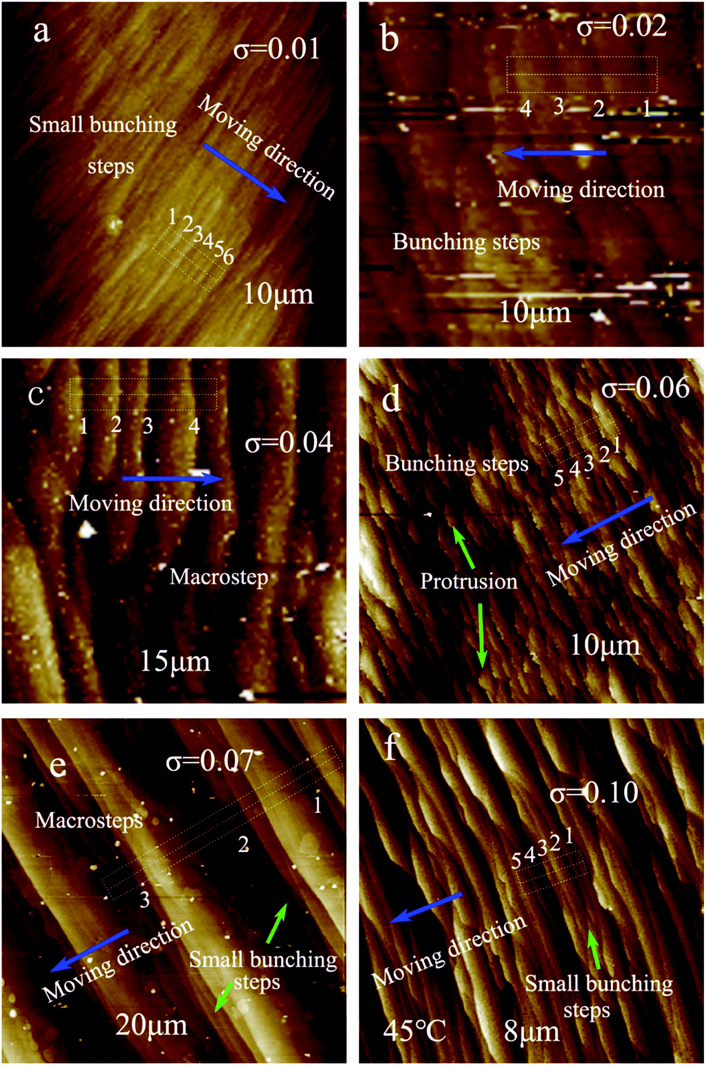
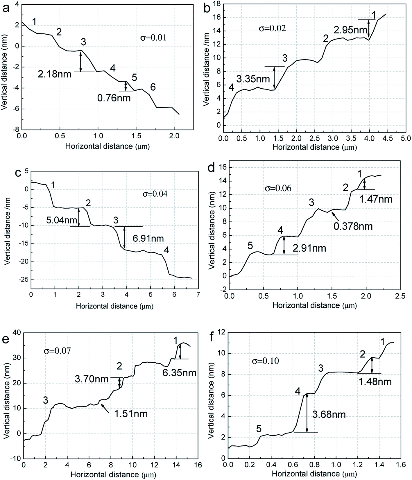
In order to understand the step evolution in different supersaturation regions, the micro morphology at a representative supersaturation point was observed by AFM and the results are shown in Fig. 3(a)–(f). The areas marked with white dotted boxes in the AFM images were chosen to measure the step height and terrace width, and the structures are shown in Fig. 4(a)–(f).
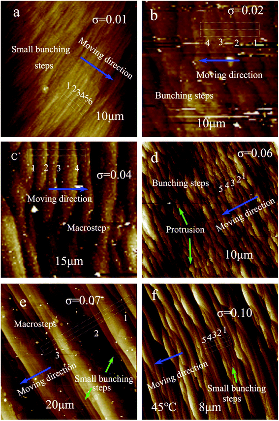 |
| | Fig. 3 Micro morphology of the (100) face in different supersaturation regions. (a) σ = 0.01, (b) σ = 0.02, (c) σ = 0.04, (d) σ = 0.06, (e) σ = 0.07, and (f) σ = 0.10. | |
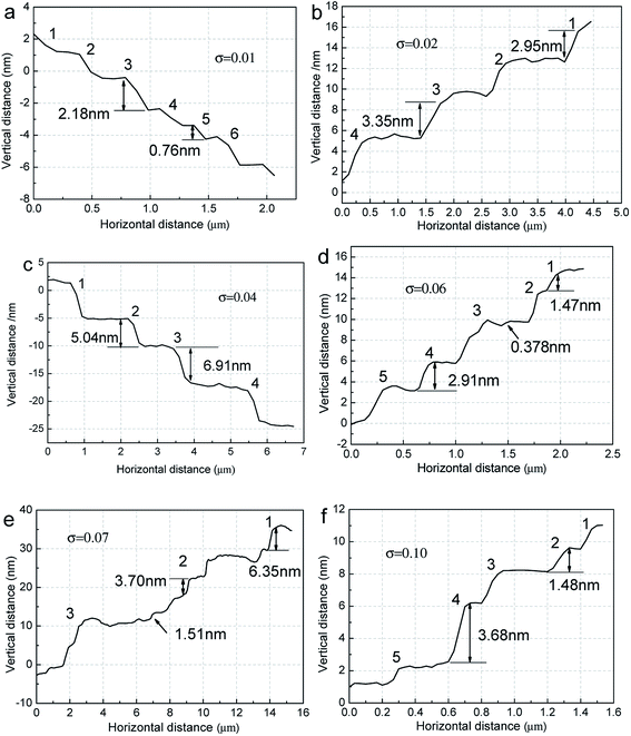 |
| | Fig. 4 Step height and terrace width of the areas marked with white dotted boxes in the AFM images. (a) σ = 0.01, (b) σ = 0.02, (c) σ = 0.04, (d) σ = 0.06, (e) σ = 0.07, and (f) σ = 0.10. | |
Combining the information shown in Fig. 3 and 4, it can be seen that the surface micro morphology and step structure show obvious changes in the different supersaturation regions. At a low supersaturation of σ = 0.01, there are mainly small bunched together steps on the crystal surface, resulting in a compact step distribution. At σ = 0.02 and σ = 0.04, the steps overlap with each other and the step height increases, which is more pronounced at σ = 0.04. When the supersaturation is 0.06, the steps are bent, and some protrusions occur on the terrace due to the fast growth speed. The step height decreases, and elementary steps appear on the terrace. For the critical supersaturation point at σ′ = 0.07, the steps are straight, and the step bunching is very pronounced. Some small bunched together steps appear at the ledge of macro steps. When the supersaturation is 0.10, the steps become smooth, and the bunching together is far less pronounced than at σ = 0.07. In addition, the terrace width is the widest at σ = 0.07.
3.3 Laser damage threshold (LDT) versus supersaturation
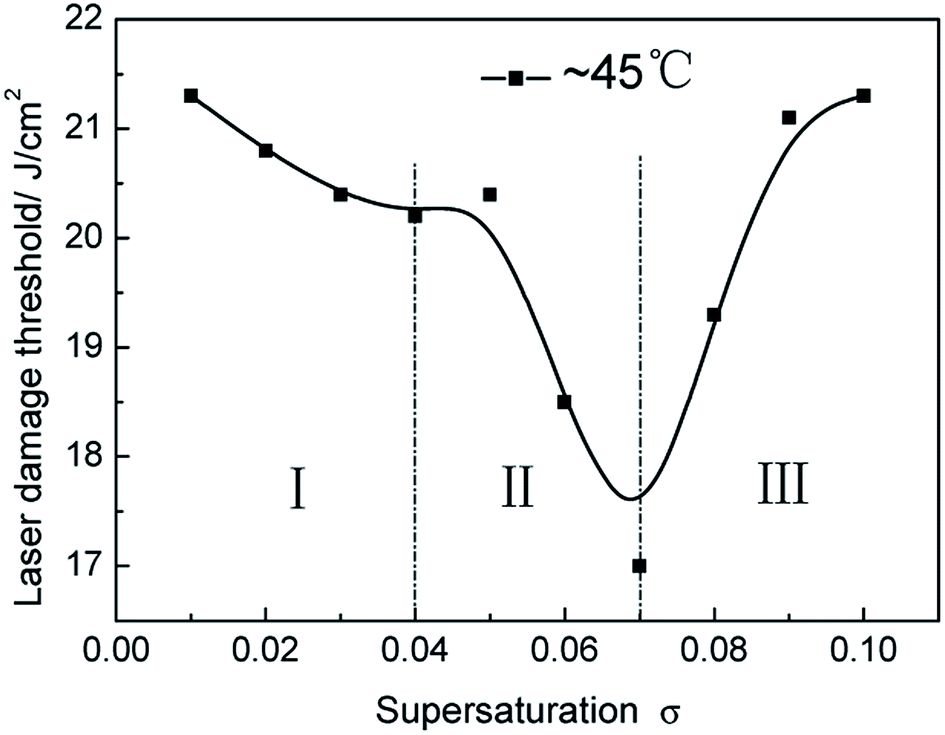
The relationship between the LDT and supersaturation is shown in Fig. 5. It is clear to see that the LDT of the crystals first reduces, then increases, upon an increase in the supersaturation. The curve of LDT-(σ) can be divided into three zones, which are consistent with the zone divisions related to the dependence of v–(σ). The change in the LDT is relatively small at low supersaturation in area I, and has a maximum value of around 21.3 J cm−2 at σ = 0.01. The LDT of the crystals reduces quickly in the supersaturation range of σ = 0.04–0.07 in area II, the lowest value being around 17 J cm−2 at σ = 0.07. When the supersaturation is high and in area III, the LDT rises fast and finally ends up having a similar value to that at low supersaturation.
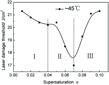 |
| | Fig. 5 Dependence of LDT on supersaturation when the saturation temperature is around 45 °C. | |
4. Discussion
4.1 High LDT in low supersaturation area I
The data show that the LDT of crystals grown at low supersaturation is high. It is thought that this may be due to the low step velocity in this supersaturation region. It has been reported that the LDT may be dependent on the light scattering in the crystal, i.e. the higher the scattering density, the lower the LDT.22 The light scattering may be related to mother liquor inclusions that form during the process of crystal growth.23 In low supersaturation area I, crystal growth is achieved by the evolution of small bunched up steps, that are dense and uniform, with a slow step velocity, as shown in Fig. 3. It is difficult to form inclusions in the crystals because there are few light scattering centers, and the crystal quality is good. The results are in good agreement with those of Zhu et al.24
4.2 LDT reduces at the transition supersaturation zone of area II
The experimental results indicate that the LDT of the crystals quickly reduces and the step velocity quickly increases in the transition supersaturation zone of area II. This may be attributed to the supersaturation points being located in different regions in the process of crystal growth. According to the research of Rashkovich et al.,25 the range of supersaturation where the derivative dv/dσ is high is the most problematic for crystal growth. Within this range, the change in the adsorbed impurity concentration and surface supersaturation causes significant variation in the velocity. The variation in the velocity of a single step in the step column leads to the bunching together of steps. The experimental data are highly consistent with the theory. From the curve in Fig. 2, it can be seen that the range lies in the supersaturation region from σ = 0.04 to 0.07. As shown in Fig. 3 and 4, the bunching together of steps increases at σ = 0.06 and 0.07, and is more pronounced at σ = 0.07. The mother liquor may be packaged into the crystal and form inclusions during the movement of large macro steps. Light scattering is further intensified upon an increase in mother liquor inclusions in the crystal, resulting in a rapid decrease in the LDT.
4.3 LDT rises again in the high supersaturation region of area III
It was found that the crystal LDT increased again when the supersaturation exceeded the critical supersaturation point σ′. The increase in the speed slowdown in the supersaturation zone is where the dependence v–(σ) becomes a straight line that passes through the origin. The supersaturation is much greater than the linear region σ*, with both the normal growth rate R and tangential speed V increasing upon the rise in the supersaturation, and the elementary steps and macro steps both moving with a similar speed, leading to crystal growth that is not based on a bunching together of steps. The steps are smooth and uniform, as shown in Fig. 3(f). Rashkovich20 has reported that the effect of impurities turns out to be insignificant in this region of supersaturation. Thus, the step bunching is small at high supersaturation in area III, as shown in Fig. 4(f). The rise in the LDT may be as a result of the movement of bunched together steps.
5. Conclusion
The dependence of LDT-(σ) can be divided into three areas, in a similar manner to the dependence of v–(σ). At low supersaturation, the LDT is high and the step velocity is slow. In the transition supersaturation region, the LDT quickly reduces, with a minimum value of 17 J cm−2 at σ = 0.07 and a rapid increase in the step velocity. When the supersaturation is high, the LDT rises again, with the dependence of v–(σ) becoming a straight line that passes through the origin, accompanied by an increase in the slowing down speed. The change in the LDT and step velocity may be related to step movement and the bunching together of steps at different supersaturation points.
Conflicts of interest
There are no conflicts to declare.
Acknowledgements
This work was financially supported by the Nation Key Research and Development Program subject (2016YFC0800609), the Doctor Research and Innovation Program (BSKY2018001), and the National Natural Science Foundation of China (No. 51321062).
References
- H. Yoshida, T. Jitsuno, H. Fujita, M. Nakatsuka, M. Yoshimura, T. Sasaki and K. Yoshida, Appl. Phys. B, 2000, 70(2), 195–201 CrossRef CAS.
- N. Zaitseva and L. Carman, Prog. Cryst. Growth Charact. Mater., 2001, 43(1), 1–118 CrossRef CAS.
- J. J. De Yoreo, A. K. Burnham and P. K. Whitman, Int. Mater. Rev., 2002, 47, 113–152 CrossRef CAS.
- M. F. Singleton, J. F. Cooper, B. D. Andreson and F. P. Milanovich, Appl. Phys. Lett., 1988, 52, 857–859 CrossRef CAS.
- Y. Nishida, A. Yokotani, T. Sasaki, K. Yoshida, T. Yamanaka and C. Yamanaka, Appl. Phys. Lett., 2016, 52, 420–421 CrossRef.
- Y. S. Wang, M. N. Zheng, P. Bennema, Y. S. Liu, R. Zhu, G. F. Ye, J. Bian and W. J. P. van. Enckevort, J. Phys. D: Appl. Phys., 1992, 25, 1616–1618 CrossRef CAS.
- S. M. Azhar, M. Anis, S. S. Hussaini, S. Kalainathan, M. D. Shirsat and G. Rabbani, Opt. Laser Technol., 2017, 87, 11–16 CrossRef CAS.
- A. Rousta and H. R. Dizaji, Mater. Tehnol., 2016, 50, 695–698 CrossRef CAS.
- I. M. Pritula, E. I. Kostenyukova, O. N. Bezkrovnaya, M. I. Kolybaeva, D. S. Sofronov, E. F. Dolzhenkova, A. Kanaev and V. Tsurikov, Opt. Mater., 2016, 57, 217–224 CrossRef CAS.
- B. A. Liu, G. H. Hu, Y. A. Zhao, M. X. Xu, S. H. Ji, L. L. Zhu, L. S. Zhang, X. Sun, Z. P. Wang and X. G. Xu, Opt. Laser Technol., 2013, 45, 469–472 CrossRef CAS.
- P. Rajesh, P. Ramasamy and G. Bhagavannarayana, J. Cryst. Growth, 2013, 362, 338–342 CrossRef CAS.
- E. F. Dolzhenkova, E. I. Kostenyukova, O. N. Bezkrovnaya and I. M. Pritula, J. Cryst. Growth, 2017, 478, 111–116 CrossRef CAS PubMed.
- A. Schmid, P. Kelly and P. Braunlich, Phys. Rev. B, 1997, 16, 4569–4582 CrossRef.
- S. J. Zhu, S. L. Wang, J. X. Ding, G. X. Liu, W. J. Liu, L. Liu, D. L. Wang, W. D. Li, Q. T Gu and X. G. Xu, J. Cryst. Growth, 2014, 388, 98–102 CrossRef CAS.
- Y. Wang, Y. Zhao, X. Y. Xie, G. H. Hu, L. J. Yang, Z. Y. Xu and J. D. Shao, Opt. Lett., 2016, 41, 1534–1537 CrossRef CAS PubMed.
- N. P. Zaiteseva, J. J. De Yoreo and M. R. Dehaven, J. Cryst. Growth, 1997, 180, 255–262 CrossRef.
- W. K. Burton, N. Cubrera and F. C. Frank, Philos. Trans. R. Soc. London, 1951, 243, 299–358 CrossRef.
- R. J. Rosmalen and P. Bennema, The role of hydrodynamics and supersaturation in the formation of liquid inclusions in KDP, J. Cryst. Growth, 1977, 42, 224–231 CrossRef.
- B. Liu, C. S. Fang and S. L. Wang, Cryst. Res. Technol., 2008, 43, 700–708 CrossRef CAS.
- L. N. Rashkovich, KDP family of crystals, Hilger-Bristol, 1991 Search PubMed.
- T. A. Land, T. L. Martin, S. Potapenko, G. Tayhas Palmore and J. J. De Yoreo, Nature, 1999, 399, 442–445 CrossRef CAS.
- J. Q. Zhang, S. L. Wang, C. S. Fang, X. Sun and Q. T. Gu, Effects of anionic impurities on the light scatter in KDP crystal, J. Inorg. Mater., 2007, 22(2), 268–272 CAS.
- X. Sun, X. G. Xu and Z. S. Gao, J. Cryst. Growth, 2000, 217, 404–409 CrossRef CAS.
- S. J. Zhu, S. L. Wang, J. X. Ding, G. X. Liu, D. L. Wang, L. Liu, Q. T. Gu and X. G. Xu, J. Synth. Cryst., 2013, 42, 1973–1977 CAS.
- L. N. Rashkovich and N. V. Kronsky, J. Cryst. Growth, 1997, 182, 434–441 CrossRef CAS.
|
| This journal is © The Royal Society of Chemistry 2018 |
Click here to see how this site uses Cookies. View our privacy policy here. 
 Open Access Article
 This Open Access Article is licensed under a Creative Commons Attribution-Non Commercial 3.0 Unported Licence
 a,
Yu Lia,
Shenglai Wang*b and
Wenyong Chengc
a,
Yu Lia,
Shenglai Wang*b and
Wenyong Chengc