DOI:
10.1039/C8RA07062H
(Paper)
RSC Adv., 2018,
8, 35672-35680
Use of a diatomite template to prepare a MoS2/amorphous carbon composite and exploration of its electrochemical properties as a supercapacitor
Received
23rd August 2018
, Accepted 4th October 2018
First published on 18th October 2018
Abstract
A MoS2/amorphous carbon composite was prepared using diatomite as a template and ammonium thiomolybdate/sucrose as starting materials. The composite perfectly inherits the template morphology with a porous structure, in which MoS2 possesses a structure with several layers, and amorphous carbon is partially inserted into the interlayer spaces of the MoS2, inhibiting the restacking of the MoS2 nanosheets along the (002) plane. The interlaminar distance of the adjacent MoS2 nanosheets in the composite is 1.03 nm, which is approximately twice that between adjacent MoS2 and carbon layers. The supercapacitor utilizing this composite exhibits a high specific capacitance, 167.3 F g−1 at the current density of 0.5 A g−1 and high rate capability, 96.4 F g−1 at 10 A g−1. Moreover, the capacitance retention is maintained at 93.2% after 1000 cycles, indicating excellent cycling stability. In contrast, the capacities of pure AC and MoS2 are much lower, and also the cyclability of MoS2. The overall improvement in electrochemical performance could be ascribed to the unique microstructure and the close combination of MoS2 and amorphous carbon.
Introduction
There has been great interest in electrochemical capacitors (ECs), also called supercapacitors, in recent years because of the increasing miniaturization of electronic and electrical equipment and the continuous development in the electric vehicle industry.1 ECs are a new type of energy storage device that have numerous benefits, including long cycle life, great power density, high energy density, wide working temperature range, and environmental friendliness, and have been widely used in constant switches, portable electronics, backup power supplies, and industrial power-energy management.2–4 Based on the charge storage mechanism, ECs can be classified as electrical double-layer capacitors (EDLCs) or pseudo-capacitors (PCs).5 EDLCs retain energy via gathering pure electrostatic charge at the electrode/electrolyte interface.6 PCs produce energy by the rapid reversible faradic alterations of active materials.7 Carbon-based materials with high surface area, including carbon nanotubes (CNTs),8,9 active carbon,10 and mesoporous carbon,11 have been extensively utilized in EDLCs, and electroactive materials, including conductive polymers,12 transition-metal oxides,13 transition-metal hydroxides,14 and transition-metal sulfides,15–17 have been widely used in PCs. A typical approach is to synthesise a composite by combining two materials of the PC-type and the double-layer-type capacitor, respectively, to improve the capacitive characteristics of the composite.18
MoS2 is structurally analogous to graphite and possesses a crystal structure that is made up of fragile coupled layers of S–Mo–S, in which an atomic layer of Mo appears among two layers of S atoms. The three layers are piled and jointed by fragile van der Waals interactions.19–21 Because of its unique sandwich structure, it is beneficial for the diffusion and transfer of ions to achieve the purpose of storing and releasing electrons.22 Moreover, MoS2 exhibits greater intrinsic fast ionic conductivity compared to oxides,23 greater theoretical capacity than graphite,24 and is anticipated to demonstrate positive pseudocapacitive characteristics because the Mo center is able to show a range of oxidation states from +2 to +6.25 Therefore, there has been great interest in MoS2, particularly for use in supercapacitors.20,21,26 Soon and Loh18 reported that the supercapacitor demonstration of MoS2 was equal to that of carbon nanotube array electrodes. Ajayan et al.27 reported fabrication of 2D MoS2 film-based micro-supercapacitors, which exhibited high area capacitance of 8 mF cm−2 and excellent cyclability. Geng et al.28 synthesized 3D flower-like MoS2 structures, and the obtained materials formed a typical EDLC with high capacitance and good cycling stability. Nevertheless, the specific capacitance of MoS2 remains extremely limited to energy storage applications. A promising strategy have been suggested to increase the capacitance of MoS2-based materials by combining with a group of conducting materials, such as carbon materials,29,30 conductive polymers,31,32 and metal foils.33 For example, Lu et al.34 prepared MoS2/polyaniline (PANI)/rGO aerogels, in which the PANI and graphene ensured the outstanding conductivity of the aerogels, and enhanced the total capacitance of the aerogels by providing the pseudocapacitance and EDLC, respectively.
Nowadays, template method is a hot research topic in materials science, with which the structure, morphology and size of nanomaterials can be effectively controlled by simply altering the nature of template and the preparation conditions. For the preparation of two-dimensional layered transition-metal dichalcogenide (TMD) architectures based on TMD nanomaterials, commonly used templates include metal carbonate microcubes,35 metal oxide microcubes,36 and silica microspheres.37 For example, Zhou et al.38 employed TiO2 nanobelts as templates to prepare TiO2 heterostructures coated with few-layer MoS2 nanosheets (TiO2@MoS2), which showed a high photocatalytic hydrogen production even without the Pt co-catalyst. Hu et al.39 reported the synthesis of porous tubular C/MoS2 nanocomposites with porous anodic aluminum oxide as a template, and the composite showed good electrochemical performance. Besides, other macro-sized materials including 3D graphene foams,40,41 carbon cloths,42,43 carbon fibers,44 and so on, were also studied as templates for the preparation of TMD-based materials. However, complex manufacturing processes and high prices limit the large-scale application of synthetic templates. There are many natural minerals with one-dimensional to three-dimensional structures in nature. They are excellent natural template materials because of their huge reserves and low cost. However, there are seldom reports concerning the use of natural minerals as templates for the preparation of TMD-based materials.
Herein, we propose a MoS2/amorphous carbon (a-C) composite using sucrose and ammonium thiomolybdate as the carbon and MoS2 source, respectively, and natural diatomite as a template. The electrochemical properties of such composites were further studied and determined to provide a high capacitance and high-rate capability with good long-term cycling stability.
Experimental
Diatomite
Natural diatomite was acquired from the Selet Diatomite Co., Ltd. (Jilin province, China) and purified by an acid leaching technique.45 The chemical composition (wt%) of diatomite before and after purification was established by X-ray fluorescence spectrometry (ADVANT'XP+), as summarized in Table 1.46
Table 1 Chemical compositions of diatomite before and after purification (wt%)
| Sample |
SiO2 |
Al3O2 |
Fe2O3 |
K2O |
CaO |
MgO |
Na2O |
TiO2 |
L.O.Ia |
| Loss on ignition. |
| Nature diatomite |
84.23 |
3.27 |
0.74 |
0.46 |
0.34 |
0.25 |
0.20 |
0.17 |
4.5 |
| Purified diatomite |
91.99 |
2.01 |
0.23 |
0.35 |
0.13 |
0.07 |
0.17 |
0.1 |
2.5 |
Preparation of the MoS2/a-C composite
A related schematic image is shown in Fig. 1. To prepare the precursor, 0.26 g ammonium thiomolybdate ((NH4)2MoS4) and 0.17 g sucrose were dissolved in 10 mL dimethylformamide (DMF), and then a certain amount of diatomite (0.5 g) was placed in the solution. The combination was stirred under vacuum for 30 minutes and then dried at 70 °C to obtain the product, which was then annealed at 800 °C for 2 h under argon flow. The diatomite template was removed by soaking in 40% HF solution for 12 h. After washing with water and alcohol, the product was obtained by additional drying in a vacuum oven at 70 °C for 12 h.
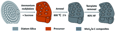 |
| | Fig. 1 Schematic representation of the formation mechanism of the MoS2/a-C composite using diatomite as template. | |
In order to investigate how the crystal structures and morphologies of the sample were affected by adding sucrose to the precursor solution, pure carbon (amorphous carbon, AC) and MoS2 were also prepared using the same route by adding the corresponding precursor and then annealing under the same conditions.
Characterization
Powder X-ray diffraction (XRD) patterns were recorded on a Rigaku DMAX-2400 diffractometer using Cu Kα radiation (λ = 0.154056 nm) with a generator voltage of 40 kV and a current of 100 mA. A scan rate of 2° min−1 was applied for the determination. Raman spectra were obtained using a Ricro-Raman-1000 micro spectrometer (Renishaw, UK) with an excitation wavelength at 532 nm. Thermogravimetry (TG) was recorded in the temperature range of 50–1000 °C in air atmosphere at a heating rate of 10 °C min−1 using TGA-DSC-DTA (TA, USA) tester. SEM micrographs were obtained using a Nova Nano SEM 430 (FEI, USA) field emission SEM with acceleration voltage of 15 kV and beam current of 176 μA. TEM images were obtained with Tecnai F30 (FEI, USA) field emission TEM at 200 kV accelerating voltage. Element distribution of the sample was characterized by using energy dispersive X-ray spectroscopy (EDS). The N2 adsorption–desorption isotherms were measured on a Micromeritics ASAP 2020 system at 77 K. Prior to analysis, the samples ware degassed under vacuum at 120 °C for 24 h. The specific surface area was calculated using the multiple-point Brunauer–Emmett–Teller (BET) method, while the pore size distribution and pore volume data were calculated from the desorption branches based on the Barrett–Joyner–Halenda (BJH) equation.47
Electrochemical measurements
Cyclic voltammetry (CV), galvanostatic charge–discharge (GCD) and electrochemical impedance spectroscopy (EIS) were carried out on a CHI660E electrochemical workstation (Shanghai, China) with a three-electrode configuration using 6 M NaOH aqueous solution as the electrolyte. The working electrode is nickel foam coated by the mixture of electroactive materials, carbon black and polytetrafluoroethylene (PTFE) with the weight ratio of 85![[thin space (1/6-em)]](https://www.rsc.org/images/entities/char_2009.gif) :10:5 in a mass loading of 1.0 mg cm−2. Platinum foil and Hg/HgO severed as counter and reference electrode, respectively. The specific capacitance was calculated from the GCD curve based on eqn (1).where I is the constant discharging current, t is discharging time, m is the mass of the corresponding electrode material, and ΔU is voltage range.
:10:5 in a mass loading of 1.0 mg cm−2. Platinum foil and Hg/HgO severed as counter and reference electrode, respectively. The specific capacitance was calculated from the GCD curve based on eqn (1).where I is the constant discharging current, t is discharging time, m is the mass of the corresponding electrode material, and ΔU is voltage range.
Results and discussion
X-ray diffraction (XRD)
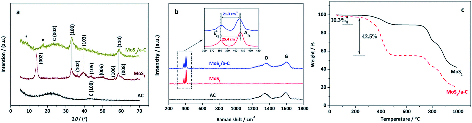
The XRD patterns of pure AC, MoS2, and the MoS2/a-C composite are demonstrated in Fig. 2a. AC exhibits two broad XRD diffractions at approximately 23° and 43°, indicating that the carbonaceous material is formless in nature. All reflections of MoS2 are in accord with the hexagonal structure (JCPDS 37-1492), which illustrates the high purity. In the MoS2/a-C composite, the (002) plane peak of MoS2 disappears, and just three XRD peaks at 2θ = 33.0°, 39.5°, and 58.9° are observed, which are ascribed to the (100), (103), and (110) peaks of MoS2, respectively. A broad diffraction peak appearing at 2θ = 25.1° should be attributed to the (002) plane of amorphous carbon. The absence of the (002) reflection of MoS2 indicates that stacking of the single layer does not occur, and MoS2 in the composite should possess a structure with a sole layer or several layers.48,49 In addition, there are two novel fragile diffraction peaks for the composite at 2θ = 8.6° and 16.4°, which are indicated with * and #, respectively. The two peaks are not indexed to MoS2 or carbon. Calculated according to the diffraction angles based on the Bragg equation, the d-spacing of peak # is 0.52 nm, which is within d(002) of MoS2 and carbon. There is the potential that peak # is ascribed to the spacing among the MoS2 layer and the carbon layer. The d-spacing of peak * is 1.03 nm, which is double that of peak #, and it could be the distance between adjacent MoS2 nanosheets.
 |
| | Fig. 2 (a) XRD patterns and (b) Raman spectra of AC, MoS2 and MoS2/a-C composite; (c) TG curves of MoS2 and MoS2/a-C composite. | |
Raman spectroscopy
Fig. 2b shows the Raman spectra of pure AC, MoS2, and the MoS2/a-C composite. Clearly, only typical D and G vibrational bands centered at 1348 cm−1 and 1583 cm−1 are observed for AC, which are from the defects and disorder structures in carbon, and the graphitic in-plane vibrations of ideal sp2 carbons, respectively.50 The characteristic bands of MoS2 exhibit at 381.7 cm−1 and 407.1 cm−1 correspond to the E12g and A1g modes, respectively, which are from the out-of plane Mo–S phonon mode and the in-plane Mo–S phonon mode.51 The frequency difference of 25.4 cm−1 between the E12g and A1g mode peaks indicates the layer-stacked structure of MoS2.52 The MoS2/a-C composite shows not only the peaks of carbon but also the peaks of MoS2, confirming the presence of carbon and MoS2 in the composite and complete correspondence with the finding from the XRD diffraction studies. In addition, compared with pure MoS2, the E12g vibration softens (red shifts), while the A1g vibration stiffens (blue shifts) with a peak to peak distance of 21.3 cm−1 in the composite, corresponding to few layer MoS2.52
Thermogravimetry (TG)
Fig. 2c shows the thermal behavior of MoS2 and MoS2/a-C composite at air atmosphere. As illustrated in the figure, both materials exhibit an initial weight loss at approximately 100 °C, which corresponds to the evaporation of surface-adsorbed water molecules.53 For MoS2, when the temperature elevated from 200 °C to 600 °C, the weight loss of 10.3% is related to the oxidation of MoS2 and the formation of MoO3, which is represented by eqn (2).54 The weight loss occurring after 600 °C is attributed to the sublimation of MoO3.55 For the MoS2/a-C composite, the TG curve is similar to that of MoS2, but the weight loss significantly increases in the temperature range of 200–600 °C (42.5%), which is mainly due to the simultaneous ablation of amorphous carbon in addition to MoS2 oxidation.56 Combined with the thermal weight loss and eqn (2), the carbon content of the composite is calculated to be approximately 36.2%.| | |
2MoS2 + 7O2 → 2MoO3 + 4SO2
| (2) |
Scanning electron microscopy (SEM)
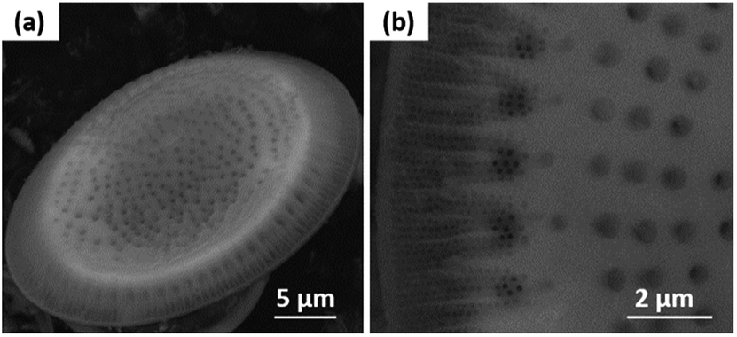
The SEM images show that the diatom shells (Fig. 3a) are disk-shaped with a diameter of 3–20 μm, and the frustule possesses two types of macroporous structures (Fig. 3b). The macropores in the center of shell array are irregularly spaced, with sizes concentrated at 300–500 nm, while the macropores at the edge display an ordered array with a pore size of 100–200 nm. Fig. 4 shows the morphologies of pure AC (Fig. 4a and d), MoS2 (Fig. 4b and e), and the MoS2/a-C composite (Fig. 4c and f). All the materials exhibit cylindrical (Fig. 4a–c) and regular hollow tubular (Fig. 4d–f) structures, originating from the center and marginal pores of diatomite, respectively. The surface morphology of the MoS2/a-C composite is rough, which increases the specific area of the nanocomposite.
 |
| | Fig. 3 SEM images of (a) a diatom shell and (b) macropores in the diatom shell. | |
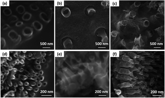 |
| | Fig. 4 SEM images of (a and d) AC, (b and e) MoS2, and (c and f) the MoS2/a-C composite. | |
Transmission electron microscopy (TEM)
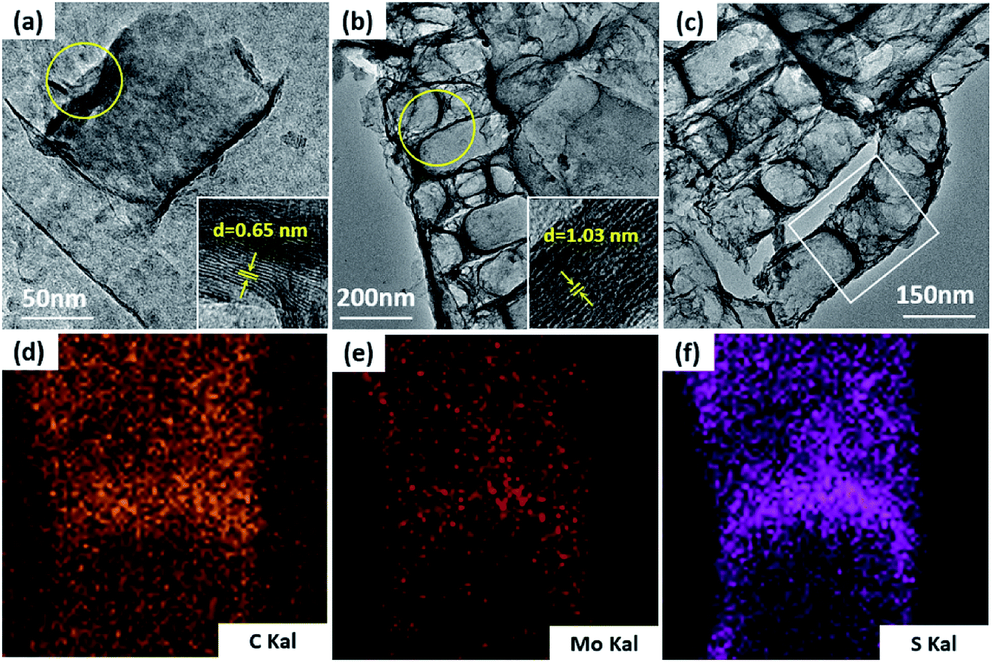
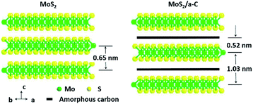
TEM was used to additionally study the microstructures of the samples. Fig. 5a demonstrates that MoS2 has an ideal layered crystal with an interlayer distance of the (002) plane of 0.65 nm, which is in agreement with the XRD results. The TEM image of the MoS2/a-C composite in Fig. 5b clearly shows that the nanotubes are porous and the layer-stacked structure of MoS2 is destroyed. The interlayer distances between the MoS2 nanosheets is 1.03 nm for the composite, which is in agreement with the XRD evaluation. Therefore, it can be established that the diffraction peak * near 2θ = 7.5° must be ascribed to the interlayer area of the nearby MoS2 nanosheets in the composite. In addition, the plane spacing d(#) is approximately half of the plane spacing of d(*), which should be the distance among the MoS2 layer and the carbon layer.
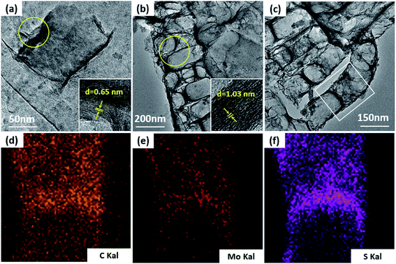 |
| | Fig. 5 TEM images of (a) MoS2, (b and c) the MoS2/a-C composite, and (d–f) elemental distribution scanning of the selected region in (c). | |
The elemental distribution was obtained by the EDS mapping, as shown in Fig. 5c–f. Three elements in the composite, C, Mo and S, are homogenously distributed, suggesting that MoS2 and C are perfectly combined. The composite microstructure is schematized in Fig. 6. MoS2 has a sandwich structure of S–Mo–S covalent bonds, with an interlayer distance of 0.65 nm. By adding sucrose to the precursor solution, amorphous carbon is partially inserted into the interlayer spaces of MoS2, escalating the distance of the initial MoS2 layers.
 |
| | Fig. 6 Schematic demonstration of the microstructures of MoS2 and the MoS2/a-C composite. | |
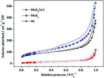
N2 adsorption
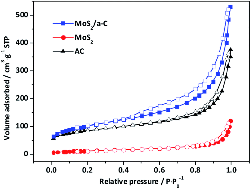
Fig. 7 shows the nitrogen adsorption/desorption isotherms of template materials. Based on IUPAC-classification, all the materials exhibit type II adsorption isotherms with H4-type hysteresis loops, and these characteristics reflect the mesoporous structure. The elevation in the quantity adsorbed close to the relative pressure of 1.0 demonstrates the presence of macropores. The adsorption curves exhibit a small amount of adsorption capacity at low relative pressure, indicating that there are a small number of micropores. The specific surface areas and pore characteristics are tabulated in Table 2. In contrast to pure AC and MoS2, the specific surface area and pore volume of the MoS2/a-C composite are significantly elevated, and the volume of both micropores and mesopores showed the same trends, but the variation trend of the average pore size is the opposite, implying that the number of pores in the composite has increased. It has been documented that (NH4)2MoS4 decomposes at low temperature to produce MoS3.57 It is possible that carbothermal reduction of MoS3 by pyrolyzed carbon leads to the creation of MoS2, and simultaneously, the gasification of carbon produces pores nearby MoS2, causing the generation of the porous tubular MoS2/a-C composite.58
 |
| | Fig. 7 Nitrogen adsorption isotherms of AC, MoS2, and the MoS2/a-C composite. | |
Table 2 Specific surface areas and pore characteristics of the prepared samples
| Sample |
Dap (nm) |
SBET (m2 g−1) |
VTotal (cm3 g−1) |
VMic (cm3 g−1) |
VMic/VTotal (%) |
VMes (cm3 g−1) |
VMes/VTotal (%) |
| MoS2 |
6.3 |
108.1 |
0.172 |
0.00781 |
4.55 |
0.0196 |
11.4 |
| AC |
5.8 |
297.5 |
0.431 |
0.0339 |
7.88 |
0.0847 |
19.7 |
| MoS2/a-C |
5.1 |
361.6 |
0.621 |
0.0700 |
11.27 |
0.138 |
22.1 |
Electrochemical properties
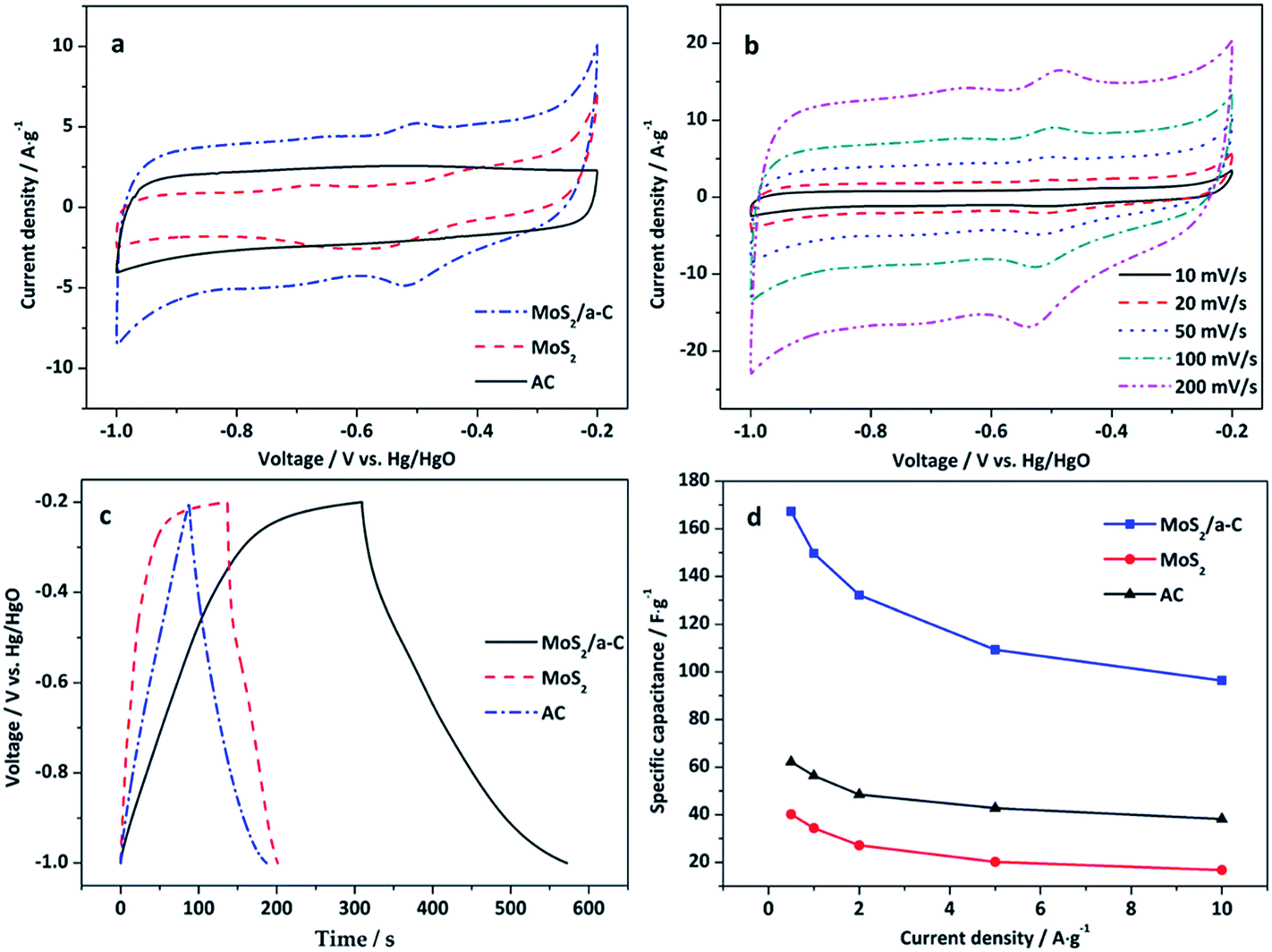
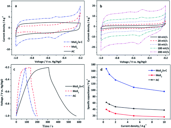
Fig. 8a reveals the CV curves of AC, MoS2, and the MoS2/a-C composite electrodes at a scan rate of 50 mV s−1 in the potential window of −1.0 to −0.2 V. There is no obvious redox peak in the CV curve of the AC electrode, which indicates typical electric double-layer capacitance. For the MoS2 and MoS2/a-C electrodes, the capacitance quality is unique from that of the electric double-layer capacitance. The two CV curves exhibit obvious redox peaks, which indicate pseudocapacitance characteristics. The redox peaks should be ascribed to the oxidation/reduction process of Mo active atoms at the edge of the MoS2 layer (Mo(IV) ↔ Mo(V) ↔ Mo(IV)).59 Compared with pure AC and MoS2, the output current of the MoS2/a-C composite is higher, indicating that the composite possesses a larger capacitance. Fig. 8b shows the CV curves of the MoS2/a-C composite at various scan rates. As the scan rate increases, the CV shape is well-maintained, indicating that the composite possesses excellent capacitive behavior and would be suitable for quick charge–discharge operations.
 |
| | Fig. 8 (a) CV curves of AC, MoS2, and the MoS2/a-C composite at 50 mV s−1; (b) CV curves of the MoS2/a-C composite at different scan rates; (c) GCD curves of AC, MoS2, and the MoS2/a-C composite at 0.5 A g−1; (d) specific capacitance at various current densities. | |
Fig. 8c displays the GCD curves of AC, MoS2, and the MoS2/a-C composite electrodes examined at a current density of 0.5 A g−1 with voltage between −1.0 and −0.2 V. For the MoS2 and MoS2/a-C electrodes, the figure reveals two variation ranges in the discharge curves, in which a variation of potential vs. time dependence (−0.2 to −0.4 V) almost parallels to the potential axis suggests pure double-layer capacitance activity from the charge separation at the electrode/electrolyte interface. In addition, a sloped variation of potential vs. time (−0.4 to −1.0 V) suggest usual pseudocapacitance activity, induced by redox reaction at the electrode/electrolyte interface.19,22 However, it is usual double-layer capacitance activity for the AC electrode.
Fig. 8d shows the variation of the specific capacitance with increasing current density. The specific capacitance of the MoS2/a-C composite is approximately 167.3 F g−1 at the current density of 0.5 A g−1, correlating to a specific capacitance of 62.2 and 40.2 F g−1 for AC and MoS2 alone, respectively. These values are agreement with the order suggested by the cyclic voltammograms. Significantly, the specific capacitance of the MoS2/a-C composite remains as high as 96.4 F g−1, even at higher current density of 10 A g−1, which indicates that the composite has a good performance at high rate. The excellent electrochemical performance of the MoS2/a-C composite may be ascribed to its unique microstructure. (1) The combination of different sizes of pores for ion-buffering reservoirs increases the diffusion rate of ions within the porous electrode material. (2) The sizable specific surface area and the nanoscale size of MoS2 substantially lower the diffusion length for ions and electrons. (3) The excellent interfacial contact between MoS2 and amorphous carbon expedites the rapid transportation of electrons during the entire electrode matrix.
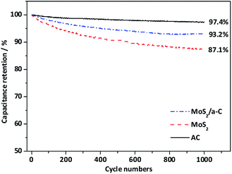
Fig. 9 shows the cycling performance of AC, MoS2, and the MoS2/a-C composite at current density of 1 A g−1. For the AC electrode, there is only a 2.6% decay in the specific capacitance after 1000 cycles, suggesting good structural stability of the template carbon. For the MoS2 and MoS2/a-C electrodes, the specific capacitance maintains at 87.1% and 93.2% after identical cycles, respectively. Obviously, the cycling performance of the composite is highly enhanced compared with that of pure MoS2. The good cycling stability of the MoS2/a-C composite may be due to the close combination of MoS2 and amorphous carbon, which not just effectively prevents the restacking of the MoS2 nanosheets, but also can accelerate ion/electron transport. Moreover, amorphous carbon existing between MoS2 nanosheets can alleviate the structural stress changes that occur during the repeated charge/discharge process.
 |
| | Fig. 9 Nyquist plot of AC, MoS2, and the MoS2/a-C composite. | |
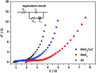
To further study the electrochemical behavior of the three electrodes, electrochemical impedance spectroscopy (EIS) was performed. The impedance spectra in Fig. 10 is made up of one semicircle at the high-frequency and then by a linear portion at the low-frequency. The equivalent circuit for the Nyquist plots is presented as an inset in Fig. 10. The first intercept of the arc on the real axis shows the value of the ohmic resistance of the electrolyte and the internal resistance of the active materials, and is indicated as Rs. The impedance arc in the high-frequency region can be demonstrated by an interfacial faradic charge transfer resistance (Rct) and a parallel constant phase element (Cd) in the position of the double-layer capacitance. After the arc, the straight line with a slope in the medium frequency demonstrates the finite-length diffusion Warburg impedance (Zw).60,61 Based on the Nyquist plots, the measured Rs of AC, MoS2, and MoS2/a-C are 0.81 Ω, 1.92 Ω, and 0.97 Ω, respectively. Moreover, the Rct values are 0.83 Ω for AC, 1.48 Ω for MoS2, and 1.23 Ω for the MoS2/a-C composite. Obviously, the Rs and Rct of the MoS2/a-C composite electrode are larger than those of AC but smaller than those of MoS2, revealing that compared with pure MoS2, the electrical conductivity of the composite is increased. These results show that the initiation of conducting amorphous carbon not just elevates the charge transfer and improves the specific capacitance, but also increases the charge/discharge cycle life.
 |
| | Fig. 10 Cycle stability of AC, MoS2, and the MoS2/a-C composite. | |
Various types of carbon–MoS2 composites have been synthesized by other methods. Table 3 shows the comparison of electrochemical performances of various carbon–MoS2 composites for supercapacitors applications. Although the performance of diatomite-templated MoS2/a-C composite is not so outstanding, the template used is much cheaper than synthesis templates and resource is abundant. Therefore, it shows promising prospect in industrial applications.
Table 3 Comparisons between the MoS2/a-C composite and other carbon–MoS2 composites reported previously for supercapacitors applications
| Electrode materials |
Method |
Capacitance |
Capacitance retention |
References |
| Flower-like mesoporous MoS2/C composite |
Hydrothermal method |
201.4 F g−1 at 0.2 A g−1 |
94.1% (1000 cycles) |
62 |
| Porous tubular C/MoS2 |
Templated method |
210 F g−1 at 1 A g−1 |
105% (1000 cycles) |
39 |
| Rambutan-like MoS2/mesoporous carbon spheres |
Hydrothermal method |
411 F g−1 at 1 A g−1 |
93.2% (1000 cycles) |
63 |
| Flower-like MoS2 nanospheres/carbon nanotubes |
Hydrothermal method |
74.05 F g−1 at 2 A g−1 |
80.8% (1000 cycles) |
64 |
| Carbon–MoS2 yolk–shell microspheres |
Hydrothermal method |
122.6 F g−1 at 1 A g−1 |
95% (3000 cycles) |
65 |
| MoS2/a-C composite |
Templated method |
167.3 F g−1 at 0.5 A g−1 |
93.2% (1000 cycles) |
This work |
Conclusions
In summary, we have prepared a MoS2/a-C nanocomposite using diatomite as a template. The composite perfectly inherits the structure of the template and forms new pores in the process of pyrolysis. In the composite, amorphous carbon is partially inserted into the interlayer spaces of the MoS2 layers, increasing the distance of the original MoS2 layers and inhibiting the restacking of the MoS2 nanosheets along the (002) plane. The established MoS2/a-C composite exhibits a great specific capacitance (167.3 F g−1 at 0.5 A g−1), high-rate capability (96.4 F g−1 at 10 A g−1), and excellent cycling stability (93.2% retention after 1000 cycles), which are ideal for use of the composite in supercapacitors. The unique microstructure and the initiation of conducting amorphous carbon have a pivotal part in the improvement of the supercapacitor performance of the MoS2/a-C composite, which increases the charge transfer, specific capacitance, as well as charge/discharge cycle life.
Conflicts of interest
There are no conflicts of interest to declare.
Acknowledgements
This research was funded by National Natural Science Foundation of China (51774016); National Program on Key Basic Research Projects (973 Program) (2014CB846000); Test Fund of Peking University (0000012321).
Notes and references
- A. Pendashteh, M. F. Mousavi and M. S. Rahmanifar, Electrochim. Acta, 2013, 88, 347–357 CrossRef CAS.
- J. R. Miller and A. F. Burke, Electrochem. Soc. Interface, 2008, 17, 53–57 CAS.
- A. Burke, J. Power Sources, 2000, 91, 37–50 CrossRef CAS.
- L. Xuefeng, L. Gaoren and T. Yexiang, Sci. China: Technol. Sci., 2015, 58, 1799–1808 CrossRef.
- Y. Chen, X. Zhang, D. Zhang, P. Yu and Y. Ma, Carbon, 2011, 49, 573–580 CrossRef CAS.
- Y. Zhu, S. Murali, M. D. Stoller, K. J. Ganesh, W. Cai, P. J. Ferreira, A. Pirkle, R. M. Wallace, K. A. Cychosz, M. Thommes, D. Su, E. A. Stach and R. S. Ruoff, Science, 2011, 332, 1537–1541 CrossRef CAS PubMed.
- X. Lu, D. Zheng, T. Zhai, Z. Liu, Y. Huang, S. Xie and Y. Tong, Energy Environ. Sci., 2011, 4, 2915–2921 RSC.
- H. Zhang, G. Cao and Y. Yang, Energy Environ. Sci., 2009, 2, 932–943 RSC.
- S. W. Lee, B. S. Kim, S. Chen, Y. Shao-Horn and P. T. Hammond, J. Am. Chem. Soc., 2009, 131, 671–679 CrossRef CAS PubMed.
- T. A. Centeno and F. Stoeckli, J. Power Sources, 2006, 154, 314–320 CrossRef CAS.
- W. Zhang, Z. Huang, C. Zhou, G. Cao, F. Kang and Y. Yang, J. Mater. Chem., 2012, 22, 7158–7163 RSC.
- X. Sun, Y. Xu, J. Wang and S. Mao, Int. J. Electrochem. Sci., 2012, 7, 3205–3214 CAS.
- Y. Hou, Y. Cheng, T. Hobson and J. Liu, Nano Lett., 2010, 10, 2727–2733 CrossRef CAS PubMed.
- J. Zhang, L. Kong, J. Cai, H. Li, Y. Luo and L. Kang, Microporous Mesoporous Mater., 2010, 132, 154–162 CrossRef CAS.
- Q. Wang, L. Jiao, H. Du, J. Yang, Q. Huan, W. Peng, Y. Si, Y. Wang and H. Yuan, CrystEngComm, 2011, 13, 6960–6963 RSC.
- T. Zhu, H. B. Wu, Y. Wang, R. Xu and X. W. D. Lou, Adv. Energy Mater., 2012, 2, 1497–1502 CrossRef CAS.
- B. Hu, X. Qin, A. M. Asiri, K. A. Alamry, A. O. Al-Youbi and X. Sun, Electrochem. Commun., 2013, 28, 75–78 CrossRef CAS.
- J. M. Soon and K. P. Loh, Electrochem. Solid-State Lett., 2007, 10, A250 CrossRef CAS.
- K. Huang, L. Wang, Y. Liu, H. Wang, Y. Liu and L. Wang, Electrochim. Acta, 2013, 109, 587–594 CrossRef CAS.
- G. Ma, H. Peng, J. Mu, H. Huang, X. Zhou and Z. Lei, J. Power Sources, 2013, 229, 72–78 CrossRef CAS.
- K. Chang and W. Chen, Chem. Commun., 2011, 47, 4252–4254 RSC.
- M. Li, S. Shen, G. Luo and L. Zhang, Chin. J. Inorg. Chem., 2017, 33, 1521–1526 CAS.
- N. Zheng, X. Bu and P. Feng, Nature, 2004, 35, 428–432 Search PubMed.
- J. Xiao, D. Choi, L. Cosimbescu, P. Koech, J. Liu and J. P. Lemmon, Chem. Mater., 2010, 22, 4522–4524 CrossRef CAS.
- Z. He and W. Que, Appl. Mater. Today, 2016, 3, 23–56 CrossRef.
- K. Huang, L. Wang, Y. Liu, Y. Liu, H. Wang, T. Gan and L. Wang, Int. J. Hydrogen Energy, 2013, 38, 14027–14034 CrossRef CAS.
- L. Cao, S. Yang, W. Gao, Z. Liu, Y. Gong, L. Ma, G. Shi, S. Lei, Y. Zhang, S. Zhang, R. Vajtai and P. M. Ajayan, Small, 2013, 9, 2905–2910 CrossRef CAS PubMed.
- X. Wang, J. Ding, S. Yao, X. Wu, Q. Feng, Z. Wang and B. Geng, J. Mater. Chem. A, 2014, 2, 15958–15963 RSC.
- L. David, R. Bhandavat and G. Singh, ACS Nano, 2014, 8, 1759–1770 CrossRef CAS PubMed.
- Y. M. Chen, X. Y. Yu, Z. Li, U. Paik and X. W. Lou, Sci. Adv., 2016, 2, e1600021 Search PubMed.
- L. Ren, G. Zhang, Z. Yan, L. Kang, H. Xu, F. Shi, Z. Lei and Z. Liu, ACS Appl. Mater. Interfaces, 2015, 7, 28294–28302 CrossRef CAS PubMed.
- J. Zhu, W. Sun, D. Yang, Y. Zhang, H. H. Hoon, H. Zhang and Q. Yan, Small, 2015, 11, 4123–4129 CrossRef CAS PubMed.
- N. Choudhary, M. Patel, Y. Ho, N. B. Dahotre, W. Lee, J. Y. Hwang and W. Choi, J. Mater. Chem. A, 2015, 3, 2449–2454 RSC.
- C. Sha, B. Lu, H. Mao, J. Cheng, X. Pan, J. Lu and Z. Ye, Carbon, 2016, 99, 26–34 CrossRef CAS.
- L. Zhang, H. B. Wu, Y. Yan, X. Wang and X. W. D. Lou, Energy Environ. Sci., 2014, 7, 3302–3306 RSC.
- X. Yu, H. Hu, Y. Wang, H. Chen and X. W. D. Lou, Angew. Chem., Int. Ed., 2015, 54, 7395–7398 CrossRef CAS PubMed.
- Z. Lin, A. Mccreary, N. Briggs, S. Subramanian, K. Zhang, Y. Sun, X. Li, N. J. Borys, H. Yuan, S. K. Fullerton-Shirey, A. Chernikov, H. Zhao, S. Mcdonnell, A. M. Lindenberg, K. Xiao, B. J. Le Roy, M. Drndi, J. C. M. Hwang, J. Park, M. Chhowalla, R. E. Schaak, A. Javey, M. C. Hersam, J. Robinson and M. Terrones, 2D Mater., 2016, 3, 42001 CrossRef.
- W. Zhou, Z. Yin, Y. Du, X. Huang, Z. Zeng, Z. Fan, H. Liu, J. Wang and H. Zhang, Small, 2013, 9, 140–147 CrossRef CAS PubMed.
- B. Hu, X. Qin, A. M. Asiri, K. A. Alamry, A. O. Al-Youbi and X. Sun, Electrochim. Acta, 2013, 100, 24–28 CrossRef CAS.
- J. Wang, J. Liu, D. Chao, J. Yan, J. Lin and Z. X. Shen, Adv. Mater., 2014, 26, 7162–7169 CrossRef CAS PubMed.
- J. Wang, J. Liu, H. Yang, D. Chao, J. Yan, S. V. Savilov, J. Lin and Z. X. Shen, Nano Energy, 2016, 20, 1–10 CrossRef CAS.
- F. Xiong, Z. Cai, L. Qu, P. Zhang, Z. Yuan, O. K. Asare, W. Xu, C. Lin and L. Mai, ACS Appl. Mater. Interfaces, 2015, 7, 12625–12630 CrossRef CAS PubMed.
- T. Lei, W. Chen, J. Huang, C. Yan, H. Sun, C. Wang, W. Zhang, Y. Li and J. Xiong, Adv. Energy Mater., 2017, 7, 1601843 CrossRef.
- F. Zhou, S. Xin, H. Liang, L. Song and S. Yu, Angew. Chem., Int. Ed., 2014, 53, 11552–11556 CrossRef CAS PubMed.
- O. Şan, R. Gören and C. Özgür, Int. J. Miner. Process., 2009, 93, 6–10 CrossRef.
- A. Li, X. Chuan, Y. Yang, X. Cao, D. Huang and Z. Yang, Electrochemistry, 2017, 85, 708–714 CrossRef CAS.
- G. Horváth and K. Kawazoe, J. Chem. Eng. Jpn., 1983, 16, 470–475 CrossRef.
- K. S. Liang, R. R. Chianelli, F. Z. Chien and S. C. Moss, J. Non-Cryst. Solids, 1986, 79, 251–273 CrossRef CAS.
- H. S. S. Ramakrishna Matte, A. Gomathi, A. K. Manna, D. J. Late, R. Datta, S. K. Pati and C. N. R. Rao, Angew. Chem., Int. Ed., 2010, 49, 4059–4062 CrossRef PubMed.
- D. Wang, G. Fang, T. Xue, J. Ma and G. Geng, J. Power Sources, 2016, 307, 401–409 CrossRef CAS.
- Y. Yang, H. Fei, G. Ruan, C. Xiang and J. M. Tour, Adv. Mater., 2014, 26, 8163–8168 CrossRef CAS PubMed.
- C. Lee, H. Yan, L. E. Brus, T. F. Heinz, J. Hone and S. Ryu, ACS Nano, 2010, 4, 2695–2700 CrossRef CAS PubMed.
- H. Li, X. Zhang, R. Ding, L. Qi and H. Wang, Electrochim. Acta, 2013, 108, 497–505 CrossRef CAS.
- S. Park, S. Yu, S. Woo, B. Quan, D. Lee, M. K. Kim, Y. Sung and Y. Piao, Dalton Trans., 2013, 42, 2399–2405 RSC.
- Y. L. Cai, Y. F. Li, Z. M. Wang, Y. Zhang, J. Chen and X. L. Guo, J. Inorg. Mater., 2016, 31, 1289–1294 CrossRef.
- Z. Wang, L. Ma, W. Chen, G. Huang, D. Chen, L. Wang and J. Y. Lee, RSC Adv., 2013, 3, 21675–21684 RSC.
- M. Nath, A. Govindaraj and C. N. R. Rao, Adv. Mater., 2001, 13, 283–286 CrossRef CAS.
- M. Lefevre, E. Proietti, F. Jaouen and J. P. Dodelet, Science, 2009, 324, 71–74 CrossRef CAS PubMed.
- R. Cammack, M. J. Barber and R. C. Bray, Biochem. J., 1976, 157, 469–478 CrossRef CAS PubMed.
- J. Yan, Z. Fan, T. Wei, W. Qian, M. Zhang and F. Wei, Carbon, 2010, 48, 3825–3833 CrossRef CAS.
- Y. Xiao, A. Zhang, S. Liu, J. Zhao, S. Fang, D. Jia and F. Li, J. Power Sources, 2012, 219, 140–146 CrossRef CAS.
- L. Fan, G. Liu, C. Zhang, J. Wu and Y. Wei, Int. J. Hydrogen Energy, 2015, 40, 10150–10157 CrossRef CAS.
- S. Zhang, R. Hu, P. Dai, X. Yu, Z. Ding, M. Wu, G. Li, Y. Ma and C. Tu, Appl. Surf. Sci., 2017, 396, 994–999 CrossRef CAS.
- M. Chen, Y. Dai, J. Wang, Q. Wang, Y. Wang, X. Cheng and X. Yan, J. Alloys Compd., 2017, 696, 900–906 CrossRef CAS.
- J. Wang, M. Chen, X. Yan, C. Zhou, Q. Wang, D. Wang, X. Yuan, J. Pan and X. Cheng, J. Appl. Electrochem., 2018, 48, 509–518 CrossRef CAS.
|
| This journal is © The Royal Society of Chemistry 2018 |
Click here to see how this site uses Cookies. View our privacy policy here. 
 Open Access Article
 This Open Access Article is licensed under a Creative Commons Attribution-Non Commercial 3.0 Unported Licence
 a,
Aijun Liac,
Xi Caob,
Fangfang Liua,
Siyu Chenga and
Xiuyun Chuan*a
a,
Aijun Liac,
Xi Caob,
Fangfang Liua,
Siyu Chenga and
Xiuyun Chuan*a