
 Open Access Article
 This Open Access Article is licensed under a
 Creative Commons Attribution 3.0 Unported Licence
An investigation of the role acceptor side chains play in the processibility and efficiency of organic solar cells fabricated from small molecular donors featuring 3,4-ethylenedioxythiophene cores†
N. A. Mica‡
 a,
S. A. J. Almahmoud‡b,
L. Krishnan Jagadammaa,
G. Cooke*b and
I. D. W. Samuel*a
a,
S. A. J. Almahmoud‡b,
L. Krishnan Jagadammaa,
G. Cooke*b and
I. D. W. Samuel*a
aOrganic Semiconductor Centre, SUPA, School of Physics and Astronomy, St Andrews, Fife, KY16 9SS, UK
bGlasgow Centre for Physical Organic Chemistry (GCPOC), WestCHEM, School of Chemistry, University of Glasgow, Glasgow, G12 8QQ, UK
First published on 23rd November 2018
Abstract
Organic photovoltaic devices fabricated from small molecular donors continue to receive significant interest due to their desirable properties such as convenient synthesis, purification and batch-to-batch reproducibility. In this study, we have synthesized two small molecules based on an alternating A–D–A structure, utilizing a central EDOT donor moiety and either 2-ethylhexyl cyanoacetate (SAM-72) or N-(2-ethylhexyl)cyanoacetamide (SAM-80) units as acceptor termini. The small molecules were incorporated into bulk heterojunction solar cells with PC71BM. Our investigations have shown that the side chains utilized for SAM-80 only allow for solution processing using volatile solvents, such as chloroform, which limits the reproducibility of device fabrication. However, SAM-72 displays better solubility and devices fabricated using a SAM-72:PC71BM active layer reached average power conversion efficiencies of 1.9%, with fill factors reaching 60%. Post-processing methods such as thermal and solvent vapor annealing were found to significantly increase the stability of devices, but were not able to improve overall device performance.
Introduction
The application of organic materials as the active component of solar cells has received significant attention in view of their increasing power conversion efficiencies (PCEs) and has provided organic photovoltaic (OPV) devices as promising alternatives to silicon based solar cells.1,2 Conducting polymers have been widely utilized in bulk heterojunction (BHJ) devices as the donor (D) material, and have given rise to solar cells with PCEs exceeding 11%.3 However, the poor batch to batch reproducibility and limited opportunity to develop structure–property relationships of polymeric systems has led to the utilization of small molecules as the active components of BHJs as they offer a range of advantages including well-defined chemical structures, reproducible and scalable synthesis and convenient purification.4,5 Moreover, small molecule-based OPVs have reached PCEs comparable with those of polymeric OPVs (∼10%).6 Small molecule donors based on oligothiophenes,7,8 diketopyrrolopyrroles,9,10 triphenylamine,11,12 and boron-dipyrromethenes,13–15 have received considerable attention, and have been incorporated in alternating donor (D) and acceptor (A) architectures connected by π-conjugated units, e.g. D–A–D16–18 and A–D–A.19–24 This architecture results in a narrow optical band gap and good light harvesting ability,21,25 and some A–D–A systems have shown good device performance with fill factors (FF) approaching 70%.6,26–373,4-Ethylenedioxythiophene (EDOT) is a well-studied building block for the development of π-conjugated materials and has been incorporated into small molecule and polymeric systems with OPV applications.2,38 The two electron donating oxygen moieties at β positions of the thiophene ring increase the electron donating ability compared to the parent heterocycle whilst simultaneously giving rise to non-covalent interactions (sulfur–oxygen) thereby increasing the rigidification of the π-conjugated system.39 Although EDOT has been widely used as a π-linker in D–A type dyes in dye sensitized solar cells (DSSC),40–45 to the best of our knowledge, EDOT-based small molecules for BHJ devices have largely utilized a D–A type architecture,2,44,46 and relatively little has been focused on A–D–A architectures.47,48 In this article, we report the synthesis of symmetrical A–D–A based systems featuring electron rich EDOT cores and their application as solution processed BHJ solar cells with the acceptor [6,6]-phenyl C71-butyric acid methyl ester (PC71BM). The molecules were designed to feature EDOT as the central donor moiety with adjacent thiophene π-conjugated units to increase the electron donating ability of the donor component. We have utilized 2-ethylhexylcyanoacetate (SAM-72) and N-(2-ethylhexyl)cyanoacetamide (SAM-80) as the terminal acceptor groups, which have been previously shown to be promising terminal acceptor moieties.8,49–52 The chemical structure of the molecules are shown in Scheme 1. The cyanoacetamide unit was included in this study due to the propensity of the amide unit to participate in hydrogen bonding, which may modulate the packing structure via intermolecular interactions and may promote self-assembly of the small molecules within their thin films, resulting in the enhancement of fill factor (FF) and power conversion efficiency. Devices were then fully optimized by various post-processing methods such as thermal and solvent vapor annealing.53,54 We also present a qualitative discussion about the morphology of the BHJs and the stability of these solar cells in ambient conditions.
 | ||
| Scheme 1 Synthetic route of SAM-72 and SAM-80 (EH = 2-ethylhexyl). | ||
Results and discussion
Synthesis
The synthesis of the target molecules SAM-72 and SAM-80 is shown in Scheme 1. Compound 2 was synthesized using a reported procedure of a similar compound.55 Compounds 3 (ref. 56) and 6 (ref. 57) were prepared using known procedures. Knoevenagel condensation of compound 1 with the two acceptors 2 and 3 gave compounds 4 and 5 which were coupled to the reagent 6 to give the final molecules SAM-72 and SAM-80 in 51% and 54% yield, respectively.Theoretical calculations
DFT calculations were conducted to study the electronic structure of SAM-72 and SAM-80. Ground state optimized geometry in Fig. 1 gave rise to planar structure for both molecules, with delocalized HOMO/LUMOs located over the molecular backbone. This planarity is an important feature as it promotes stacking interactions via π–π interactions, resulting in a material that can form good film quality with high molecular order.45 HOMO, LUMO and Eg energy levels estimated by DFT calculations are summarized in Table 1. | ||
| Fig. 1 HOMO/LUMO maps of SAM-72 and SAM-80 predicted by DFT calculations. | ||
| Molecule | Theoretical calculations | Optical properties | Electrochemical properties | |||||||
|---|---|---|---|---|---|---|---|---|---|---|
| HOMO (eV) | LUMO (eV) | Eg (eV) | λmax (nm) | λonset (nm) | Eopt (eV) | ε (L mol−1 cm−1) | IP (eV) | EA (eV) | Efund (eV) | |
| SAM-72 | −5.46 | −3.41 | 2.05 | 548 | 647 | 1.82 | 88![[thin space (1/6-em)]](https://www.rsc.org/images/entities/char_2009.gif) 700 700 |
−5.08 | −3.20 | 1.88 |
| SAM-80 | −5.36 | −3.27 | 2.09 | 536 | 629 | 1.97 | 58600 |
−5.10 | −3.14 | 1.96 |
Optical properties
Fig. 2 shows the UV-Vis absorption spectra of SAM-72 and SAM-80 in dichloromethane (DCM) solution, and their absorption properties are summarized in Table 1. Both molecules have a very similar absorption profile with absorption onset (λonset) at 647 nm and 629 nm for SAM-72 and SAM-80, respectively. SAM-72 shows a maximum absorption (λmax) at 548 nm, and a slight bathochromic shift (∼12 nm) compared to SAM-80. This suggests that the cyanoacetate terminal group has a slightly stronger accepting property than cyanoacetamide group. The optical band gap (Eg) of SAM-72 (1.82 eV) is also found to be 0.15 eV smaller than SAM-80 (1.97 eV). SAM-72 also shows a strong absorption in the visible region with a molar extinction coefficient (ε) of 88700 L mol−1 cm−1.
 | ||
| Fig. 2 UV-Vis absorption spectra of SAM-72 and SAM-80 in DCM (1 × 10⁻⁵ M). | ||
Electrochemical properties
The electrochemical properties of SAM-72 and SAM-80 were determined by square wave voltammetry and the data are summarized in Table 1. Both molecules show two oxidation waves at reasonably low potentials (Fig. 3). Ionization potentials (IP), electron affinity (EA), and fundamental band gap (Efund) were estimated from the oxidation and reduction potentials, respectively, and showed that the Efund of SAM-80 is ∼0.08 eV larger than that of SAM-72. SAM-80 also shows lower IP (−5.10 eV) compared to SAM-72. This suggests that the change in terminal acceptors from cyanoacetamide to cyanoacetate increases the HOMO/IP level which can change the open circuit voltage (Voc) in OPV devices, as Voc is proportional to the difference between the HOMO level of the donor and the LUMO level of the acceptor (i.e., PC71BM).58,59 | ||
| Fig. 3 Square-wave voltammograms of SAM-72 and SAM-80 in DCM (1 × 10⁻³ M) (V vs. Fc/Fc+). | ||
Device application and optimisation
After the synthesis of these donor materials, the next step was to test their photovoltaic performance in solar cells by analyzing their current–voltage (J–V) curves and external quantum efficiency (EQE) spectra. Initially SAM-80 and SAM-72 were tested by making solutions in chloroform with the fullerene derivative PC71BM. These devices showed promise with PCEs reaching an average of 1.78% for SAM-80 (1:3 wt%) and 1.16% for SAM-72 (1:5 wt%). The corresponding J–V characteristics and OPV performance parameters are shown in ESI Fig. S1 and Table S1.† However, due to the volatile nature of chloroform, active layers formed from this solvent were not reproducible and higher boiling-point solvents needed to be used. For this we tried using either chlorobenzene or dichlorobenzene. SAM-80 was not able to reliably dissolved in these solvents, whereas SAM-72 presented excellent solubility in chlorobenzene. In order to investigate whether intermolecular hydrogen bonding (N–H⋯O![[double bond, length as m-dash]](https://www.rsc.org/images/entities/char_e001.gif) C) interactions of the acrylamide moieties were responsible for the lack of solubility of SAM-80, we have performed solid-state FT-IR and solution 1H NMR spectroscopy on this material. The IR study provided a N–H stretch (major) at 3371 cm−1 (Fig. S2†) which is consistent with hydrogen bonding interactions occurring in the solid-state.60 Dilution NMR experiments performed in CDCl3, on the other hand, did not show any evidence for N–H participation in hydrogen bonding and indicated that π–π stacking interactions are more significant (Fig. S3†).
C) interactions of the acrylamide moieties were responsible for the lack of solubility of SAM-80, we have performed solid-state FT-IR and solution 1H NMR spectroscopy on this material. The IR study provided a N–H stretch (major) at 3371 cm−1 (Fig. S2†) which is consistent with hydrogen bonding interactions occurring in the solid-state.60 Dilution NMR experiments performed in CDCl3, on the other hand, did not show any evidence for N–H participation in hydrogen bonding and indicated that π–π stacking interactions are more significant (Fig. S3†).
With reliable solubility, SAM-72 and PC71BM were combined in a 10 mg mL−1 solution using chlorobenzene. Investigation of the photovoltaic properties started with the optimization of donor to acceptor ratio in the BHJ blend solution. Due to the device performance of this blend favoring high amounts of acceptor (1:5 wt%) when using chloroform as the casting solvent, donor to acceptor weight ratios ranging from 1:4 to 1:7 were blended and used for BHJ formation using chlorobenzene. As seen in Fig. 4a, and in ESI Table S2 and Fig. S4,† the 1:6 ratio was observed to result in the highest average PCE, and was chosen to be the optimum weight ratio. When increasing the acceptor amount in the blend from 1:4 to 1:6 an increase in device FF and overall PCE was observed. This trend stops when using the 1:7 weight ratio blend, where we observe a drop in FF and decrease in current from 3.69 mA cm−2 to 3.55 mA cm−2.
BHJ processing methods such as thermal annealing,53,61–63 solvent vapor annealing (SVA),54,64,65 and the use of additives66–68 have been studied in detail by various groups and shown to affect device performance. Both thermal annealing and SVA will allow the molecules to break out of their present thermodynamically unfavorable state, and rearrange themselves into a more energetically stable orientation. It has also been shown that using an additive can drastically alter donor or acceptor domain size by causing the materials to swell and reorganize.66–68 This adjustment to the domains in the photoactive layer can boost device performance by enhancing the exciton diffusion length or creating domains of optimum size to combat geminate charge recombination.69,70 In an attempt to increase the OPV efficiency, a combination of the listed processing methods were applied to the active layer.
 | ||
| Fig. 4 Box plots for each optimization step for SAM-72:PC71BM devices:(a) donor to acceptor ratio, (b) thermal annealing temperature, and (c) thermal annealing + SVA time. In each graph the average of the distribution is represented by the square in the box plot, the median is a horizontal line in the box, the ends of the box represent the data within the 25% to 75% percentile, the whiskers extending from the box are the range within 1.5 standard deviations, and the outliers are the black dots outside the boxes. | ||
To investigate the effect of thermal annealing on the photovoltaic properties of the SAM-72:PC71BM blend (1:6 wt%), the BHJ films were annealed at different temperatures ranging from 90–150 °C. The PCE of the BHJ OPV devices as a function of thermal annealing is shown in Fig. 4b. The corresponding J–V characteristics and EQE spectra are shown in ESI Fig. S5 and Table S3.† Annealing the BHJ up to 110 °C led to an increase in FF and short circuit current (Jsc), but higher annealing temperatures resulted in a decrease in these characteristics. From these initial studies of thermal annealing temperature optimization, annealing at 110 °C for 10 minutes is the optimum condition for SAM-72:PC71BM films.
After identifying the optimum thermal annealing temperature, BHJ films were exposed to carbon disulfide (CS2) vapors to undergo SVA. This solvent was chosen based on its success in SVA applications with other small molecule and fullerene BHJs.71–73 Specific details of the SVA procedure are included in the Experimental section. As seen from Fig. 4c, SVA was conducted for four different lengths of time with the highest PCE resulting from a 30 second exposure. The corresponding J–V characteristics and EQE are shown in ESI Fig. S6 and Table S4.† Exposing this BHJ to the CS2 environment for up to 30 seconds can improve device performance, mainly by increasing the FF. But, if left to SVA for longer amounts of time then the current density and FF decrease and lead to a lower PCE.
When performed in sequence, thermal annealing and SVA can produce solar cells that have the maximum Jsc of 4.34 mA cm−2 and an average PCE of 1.90% for this device structure, with the best device performing at 2.31% efficiency. This low amount of current produced in these devices likely comes from the film consisting mostly of fullerene – an acceptor which does not help device current due to its weak absorption peak in the lower-wavelength region of the visible spectrum. Another aspect hindering performance is the thickness of the active layer. When fully optimized the film is 50–60 nm thick, limiting the amount of light that the film can absorb.61 To increase this thickness the organic solution concentration was increased from 10 to 20 mg mL−1. However, full devices had efficiencies of average 1.1% and the fill factor dropped significantly to <50%. An effort was made to further improve device performance by using the additive 1,8-diiodooctane (DIO) in varied volume percentages in the solution used to make the active layer. However, any amount of DIO caused the formation of large domains not capable of working in a full device (ESI Fig. S7†).
Shown in Table 2, the application of these processing methods did not statistically improve device performance, although individual optimization experiments did show some improvement from the treatments. The best-performing device J–V curve for each processing method is shown in Fig. 5a. From this figure we can confirm the results of Table 2: thermal annealing results in the lowest FF and highest Voc, the combination of thermal and SVA leads to the lowest Voc but high FF and Jsc, and that any of these post-processing treatments results in devices that perform similarly to as-cast devices. An EQE spectrum for the different types of post-production treatments is shown in Fig. 5b. This figure shows that the thermally annealed film has the best EQE, with its maximum reaching 25% at 500 nm.
| Best PCE (%) | PCE (%) | FF (%) | Jsc (mA cm−2) | Voc (V) | |
|---|---|---|---|---|---|
| As cast | 2.25 | 1.85 ± 0.17 | 61.08 ± 2.24 | 4.13 ± 0.35 | 0.74 ± 0.01 |
| Thermal | 2.10 | 1.83 ± 0.09 | 54.17 ± 1.79 | 4.52 ± 0.26 | 0.75 ± 0.01 |
| Therm. + SVA | 2.31 | 1.90 ± 0.16 | 60.45 ± 2.96 | 4.34 ± 0.26 | 0.72 ± 0.02 |
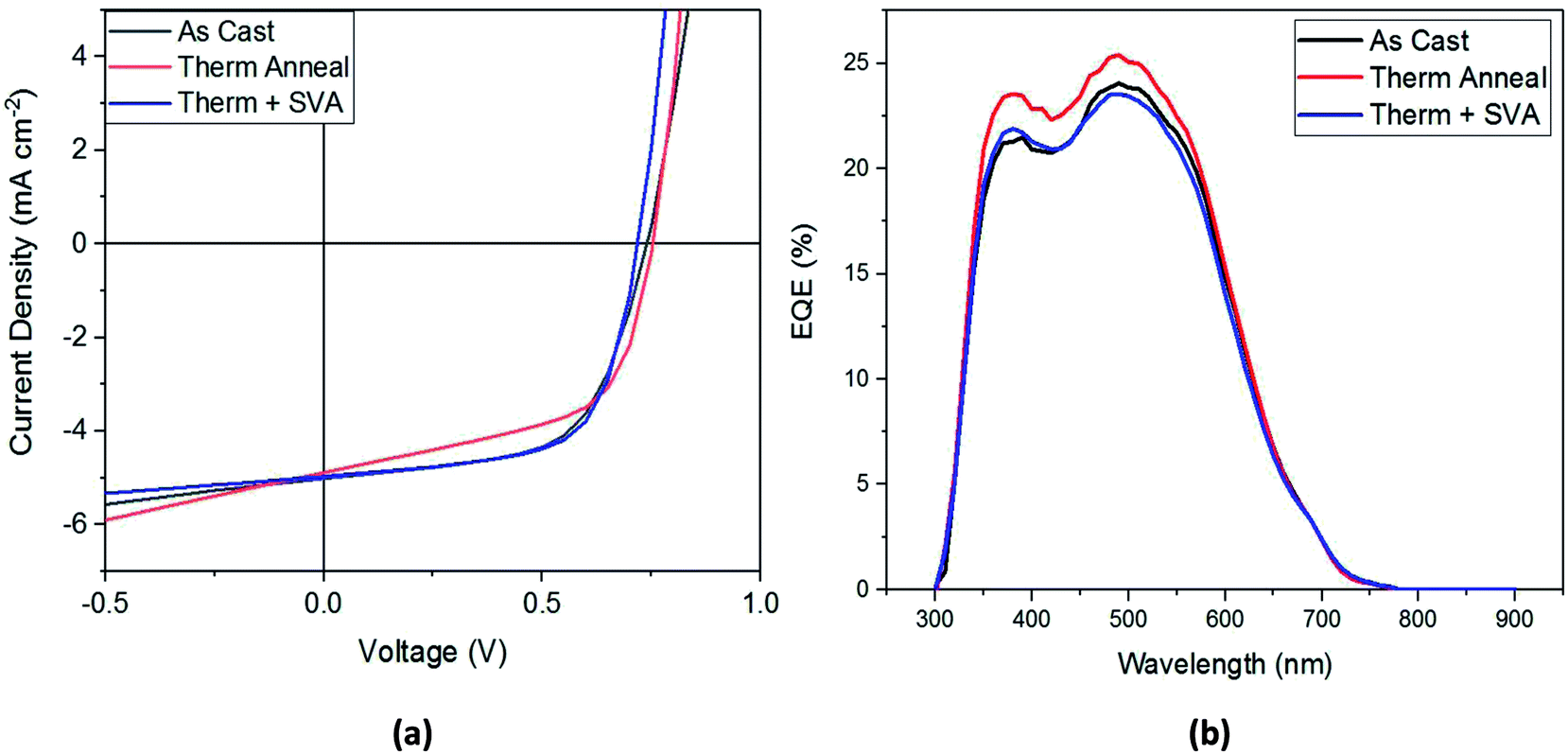 | ||
| Fig. 5 (a) Current–voltage plots and (b) EQE spectra for best performing SAM-72:PC71BM devices. | ||
When comparing the literature on other A–D–A molecule solar cells, the device performance for SAM-72:PC71BM is competitive with that of other EDOT-based molecules.44,47,48,74,75 For example, the material reported by Antwi et al. (DECA-2TE), with equivalent side chains and a similar core, showed Jsc values reaching an average of 2.99 mA cm−2 and FF of 39%.47 Likewise, another group of EDOT-based materials reported in 2013 gave solar cell device performances with all FF values < 50%.44 Similarly, in the EDOT-based molecules reported by Montcada et al. in 2013 (ref. 74) and 2015,48 only two out of the six donor molecules studied resulted in solar cells with FF > 60%. In this context we believe that SAM-72, with FF > 60% and Jsc > 4.00 mA cm−2, stands as a competitive molecule for OPV applications of EDOT-based molecules.
Morphology studies with AFM
In organic solar cells the level of performance is directly influenced by the morphology of the bulk heterojunction. Here, in Fig. 6, we present phase contrast AFM images of SAM-72:PC71BM films when subjected to different post-processing methods. As analyzed from the topographic AFM images presented in ESI Fig. S8,† initial as-cast films show well-mixed donor and acceptor domains with a surface roughness of 3.34 nm. This roughness is reduced to 0.78 nm and the domains begin to aggregate together when annealed at 110 °C for 10 minutes, and then form fiber-like structures when introduced to CS2 vapor for 30 seconds with a surface roughness of 0.67 nm. | ||
| Fig. 6 AFM phase contrast images of SAM-72:PC71BM films under different processing conditions: (a) as cast film with optimized donor to acceptor ratio; (b) thermal annealed film; (c) film that was both thermally and solvent vapor annealed. | ||
As discussed above, processing methods such as thermal or solvent vapor annealing will cause the molecules in organic films to order themselves in a lower-energy state, changing the donor and acceptor domain structures.66–68 This is observed here (Fig. 6b), as the fullerene domains begin to grow upon thermal annealing. Further optimization by SVA led to the formation of fiber-like structures. Previously these fibers have signified an increase in film crystallinity with P3HT:PCBM blends,64,67 and it is assumed here that this processing treatment also induced crystallinity.
Solar cell operational stability at 1 sun intensity
As a test of the stability of the devices, as-cast and fully post-processed solar cells were left in front of 1 sun illumination in ambient conditions for 120 hours and their performance measured at various intervals. Fig. 7 presents the PCE of these devices as a function of time. After an initial burn-in, as cast devices stabilize to an efficiency of approximately 35% of their initial value, while fully post-processed devices retain 50% of their PCE. Although device performance stays roughly the same when additional processing methods are applied to the films, the operational stability is improved as evident from Fig. 7. All devices were encapsulated before being taken out of a nitrogen environment into ambient conditions, therefore it is unlikely that water and/or oxygen was the main source of this degradation. Therefore, a morphology change in the active layer under illumination is what most likely leads to the degradation of these devices. Under illumination, the materials within the BHJ will begin to migrate and form pure domains of donor or acceptor.76 If this results in large domains then excitons generated within the domains will recombine before reaching an interface, leading to a decreased PCE. However, different morphologies of the initial BHJ, such as enhanced crystallinity,76–79 could have molecular packing that favors a more photo-stable film that will not undergo such domain growth. | ||
| Fig. 7 Ambient photo-stability of SAM-72:PC71BM devices. | ||
To investigate this argument, we compare the atomic force microscope images of as cast and fully optimized films of SAM-72:PC71BM in Fig. 6a and c. The crystalline domains that form after SVA will make the molecules more confined and chemical reactions less likely to occur – allowing for the avoidance of photo-chemical reactions which hinder the solar cell performance.76–79 Another way in which the film protects itself from these harmful reactions is by becoming denser following thermal annealing.80 In the devices presented here, spectroscopic ellipsometry measurements show that undergoing thermal and solvent vapor annealing reduces the active layer thickness by 12.5%. The as-cast films have an initial thickness of 58 nm and decrease to 50 nm when fully processed. With confirmed density and suspected crystallinity increase, the confinement of the small molecule SAM-72 in a BHJ with PC71BM is more photo-stable after it is thermally and solvent vapor annealed.
Conclusions
Here we report the synthesis of small molecule donors SAM-72 and SAM-80 featuring centrally located EDOT units and their incorporation into BHJ solar cells. We have shown that the differing side chains play a significant role in their processability, with SAM-80 being the least processible.81 On the other hand, SAM-72 which lacks the amide functionality had much better solubility which allowed BHJ cells to be fabricated with PC71BM. Optimization of the donor to acceptor weight ratio provided PCEs of 1.85% and FFs of >60%. Further active layer optimizations such as thermal and solvent vapor annealing do have a substantial impact on BHJ morphology, but do not change device performance overall and the primary impact of these post-processing methods is on the device photo-stability. After a quick burn-in period of device performance under illumination, the stability was improved by 15–20% when the film was thermally and solvent vapor annealed. Although only modest PCEs were obtained, the convenient synthesis of these materials earmark them as a promising class of materials for fabricating organic solar cells.Experimental
General
All reagents are purchased and used as received unless stated otherwise. Dry solvents were obtained from solvent purification system (activated alumina columns) (Pure Solv 400-5-MD), apart from chloroform which was purchased from Sigma Aldrich. Mass spectrometry and elemental analysis were obtained from the mass spectrometry service at the University of Glasgow. Melting points (mp) were recorded on a SMP10 Stuart Scientific melting point machine and are uncorrected. 1H NMR and 13C NMR spectroscopy were recorded on Bruker AVIII (400 MHz) spectrometer, operating at 400 MHz and 100 MHz, respectively. Chemical shifts are given in ppm and are relative to TMS, all J values are in Hz. UV-Vis measurements were carried out using a Perkin Elmer Lambda 25 spectrometer. Square wave voltammetry was recorded at room temperature under nitrogen on CH-instruments 440A potentiostat using a three electrodes cell with a platinum (Pt) working electrode, a Pt wire counter electrode and an Ag wire pseudo reference electrode. Samples were analyzed at 1.0 mM concentrations with a scan rate of 0.1 V s−1 using TBAPF6 (0.1 M in corresponding solvent) as the supporting electrolyte. The reduction potentials are referenced to ferrocene (internal or external reference) with the Fc/Fc+ redox couple adjusted to 0.0 V.Computational
Density functional theory (DFT) calculations were performed using a Gaussian 09 software. Molecular geometries were initially optimized semi-empirically (AM1) and then re-optimized by DFT using the B3LYP method with the 6-311Gdp basis set. The absence of transition states were confirmed by the absence of imaginary frequencies in vibrational frequency calculations. The 2-ethylhexyl- side chains were replaced by methyl units to aid the convergence of the geometry optimizations.Synthesis
:1) as eluent. Compound 4 was isolated as a yellow solid (0.78 g, 94%). Mp 84–85 °C. δH (400 MHz, CDCl3) 8.24 (1H, s), 7.65 (1H, d, J 4.0), 7.18 (1H, d, J 4.0), 7.14 (1H, d, J 3.9), 7.05 (1H, d, J 3.9), 4.22 (2H, dd, J 5.8, 1.9), 1.70 (1H, m), 1.39 (8H, m), 0.92 (6H, m). δC (100 MHz, CDCl3) 162.9, 146.0, 145.9, 138.8, 137.2, 134.6, 131.3, 126.5, 124.5, 115.7, 114.5, 98.5, 68.9, 38.7, 30.3, 28.9, 23.7, 22.9, 14.0, 11.0. HRMS m/z (EI+) [M+] 451.0273 (requires 451.0275 for C20H22BrNO2S2).:1) as eluent and compound 5 was isolated as a yellow solid (1.53 g, 77%). Mp 115–116 °C. δH (400 MHz, CDCl3) 8.33 (1H, s), 7.58 (1H, d, J 4.0), 7.16 (1H, d, J 4.0), 7.12 (1H, d, J 3.9), 7.04 (1H, d, J 3.9), 6.20 (1H, t, J 5.8), 3.36 (2H, td, J 6.1, 2.1), 1.54 (1H, m), 1.41–1.25 (8H, m), 0.92–0.89 (6H, m). δC (100 MHz, CDCl3) 160.5, 144.7, 144.2, 138.1, 137.4, 135.1, 131.41, 126.3, 124.6, 117.4, 114.3, 100.0, 43.64, 39.56, 31.12, 29.01, 24.39, 23.11, 14.20, 11.01. HRMS m/z (EI+) [M+] 450.0462 (requires 450.0435 for C20H23BrN2OS2).:1), and the collected product was recrystallized from MeOH. SAM-72 was isolated as a dark solid (0.07 g, 51%). Mp 195–198 °C. δH (400 MHz, CDCl3) 8.23 (2H, s), 7.64 (2H, d, J 4.0), 7.33 (2H, d, J 4.0), 7.23 (2H, d, J 4.0), 7.17 (2H, d, J 4.0), 4.48 (4H, s), 4.21 (4H, dd, J 5.8, 1.5), 1.71 (2H, m), 1.50–1.30 (16H, m), 0.96–0.93 (12H, m). δC (100 MHz, CDCl3) 163.2, 147.5, 145.9, 139.3, 138.6, 136.4, 134.1, 134.0, 126.8, 124.0, 123.9, 116.0, 110.3, 97.3, 68.8, 65.1, 38.8, 30.3, 28.9, 23.7, 22.9, 14.0, 11.0. HRMS m/z (FAB+) [M+] 884.2128 (requires 884.2116 for C46H48N2O6S5).:1), and the collected product was recrystallized from MeOH. SAM-80 was isolated as a dark solid (0.33 g, 54%). Mp 223–226 °C. δH (400 MHz, CDCl3) 8.33 (2H, s), 7.59 (2H, d, J 4.0), 7.32 (2H, d, J 4.0), 7.22 (2H, d, J 4.0), 7.18 (2H, d, J 4.0), 6.20 (2H, t, J 5.8), 4.48 (4H, s), 3.39–3.34 (4H, m), 1.55 (2H, m), 1.43–1.26 (16H, m), 0.91 (12H, m). δC (100 MHz, CDCl3) 160.7, 146.1, 144.0, 138.5, 136.1, 134.4, 134.3, 126.4, 124.0, 123.9, 117.5, 110.2, 98.8, 65.1, 43.4, 39.4, 30.9, 28.8, 24.2, 22.9, 14.0, 10.8. HRMS m/z (FAB+) [M+] 882.2454 (requires 882.2436 for C46H50N4O4S5).Device fabrication
All active layer materials were mixed in chlorobenzene for at least 6 hours at 60 °C. Fully dissolved solutions were then filtered using a 0.45 μm PTFE filter (GE Healthcare). Standard structure devices were all made with the following materials: ITO/PEDOT:PSS/active layer/Ca (10 nm)/Al (80–100 nm). Substrates with an ITO strip were first cleaned thoroughly by detergent (Hellmanex III), acetone, isopropanol, and lastly plasma ashing (GaLa Instrumente GmbH) with O2 gas. Cleaned substrates were then coated by PEDOT:PSS (Heraeus Clevios P VP AI 4083) filtered through 0.45 μm PVDF syringe tip (Millex) and spun on at 4000 rpm for 60 seconds, followed by 20 minutes of annealing at 130 °C. Devices were then transferred into a nitrogen-filled glovebox where the active layer was spun on at 900 rpm for 60 seconds. At this point the Ca/Al contact was evaporated on under a vacuum of 10−6 mbar at rates of 0.05 nm s−1 for both materials. This was followed by encapsulation using an optical epoxy (Norland Optical Epoxy) and subsequent drying under UV light for 60 seconds.Device optimisation
For thermal annealing optimization, the hotplate was allowed to reach the desired temperature and allowed to equilibrate for at least 5 minutes before annealing film. Solvent vapor annealing was done by lining a glass Petri dish (7 cm diameter) with CS2, placing the film in the center of the dish, and then covering with another dish for a controlled amount of time. The solvent additive DIO was added to the active layer solution 1 hour prior to spin coating to allow for thorough mixing.J–V measurement
Finished devices were taken out of the glovebox into ambient conditions and put under an AM 1.5 solar simulator. An external voltage was applied across the solar cell and resulting current was measured by a Keithley 2400 source meter.Stability measurement
Device stability measurements were conducted by leaving samples under ambient conditions and AM 1.5 illumination for the duration and measuring their J–V curves each time.Conflicts of interest
There are no conflicts to declare.Acknowledgements
We are grateful for funding from EPSRC under grant codes EP/L012294/1, EP/L012170/1 and EP/L015110/1. Sondos Abdullah J. Almahmoud acknowledges the Ministry of Higher Education in Saudi Arabia for the funding and support. We thank Dr S. M. Abdalhadi and Dr N. B. A. Prasetya for preparing compounds 2. The research data supporting this publication can be accessed at DOI: http://dx.doi.org/10.5525/gla.researchdata.655.Notes and references
- B. Kippelen and J.-L. Bredas, Energy Environ. Sci., 2009, 2, 251–261 RSC.
- J. Roncali, P. Leriche and P. Blanchard, Adv. Mater., 2014, 26, 3821–3838 CrossRef CAS PubMed.
- J. Zhao, Y. Li, G. Yang, K. Jiang, H. Lin, H. Ade, W. Ma and H. Yan, Nat. Energy, 2016, 1, 15027 CrossRef CAS.
- J. Roncali, Acc. Chem. Res., 2009, 42, 1719–1730 CrossRef CAS PubMed.
- Z. Li, G. He, X. Wan, Y. Liu, J. Zhou, G. Long, Y. Zuo, M. Zhang and Y. Chen, Adv. Energy Mater., 2012, 2, 74–77 CrossRef CAS.
- Y. Liu, C.-C. Chen, Z. Hong, J. Gao, Y. Yang, H. Zhou, L. Dou, G. Li and Y. Yang, Sci. Rep., 2013, 3, 3356 CrossRef PubMed.
- C. Uhrich, R. Schueppel, A. Petrich, M. Pfeiffer, K. Leo, E. Brier, P. Kilickiran and P. Baeuerle, Adv. Funct. Mater., 2007, 17, 2991–2999 CrossRef CAS.
- Y. Liu, X. Wan, F. Wang, J. Zhou, G. Long, J. Tian, J. You, Y. Yang and Y. Chen, Adv. Energy Mater., 2011, 1, 771–775 CrossRef CAS.
- Y. Patil, R. Misra, M. K. Singh and G. D. Sharma, Phys. Chem. Chem. Phys., 2017, 19, 7262–7269 RSC.
- A. Tang, C. Zhan, J. Yao and E. Zhou, Adv. Mater., 2017, 29, 1600013 CrossRef PubMed.
- S. Roquet, A. Cravino, P. Leriche, O. Alévêque, P. Frère and J. Roncali, J. Am. Chem. Soc., 2006, 128, 3459–3466 CrossRef CAS PubMed.
- H. Shang, H. Fan, Y. Liu, W. Hu, Y. Li and X. Zhan, Adv. Mater., 2011, 23, 1554–1557 CrossRef CAS PubMed.
- T. Rousseau, A. Cravino, E. Ripaud, P. Leriche, S. Rihn, A. De Nicola, R. Ziessel and J. Roncali, Chem. Commun., 2010, 46, 5082–5084 RSC.
- W. Liu, A. Tang, J. Chen, Y. Wu, C. Zhan and J. Yao, ACS Appl. Mater. Interfaces, 2014, 6, 22496–22505 CrossRef CAS PubMed.
- L. Xiao, H. Wang, K. Gao, L. Li, C. Liu, X. Peng, W.-Y. Wong, W.-K. Wong and X. Zhu, Chem.–Asian J., 2015, 10, 1513–1518 CrossRef CAS PubMed.
- Q. Shi, P. Cheng, Y. Li and X. Zhan, Adv. Energy Mater., 2012, 2, 63–67 CrossRef CAS.
- M. Nazim, S. Ameen, H.-K. Seo and H. S. Shin, Sci. Rep., 2015, 5, 11143 CrossRef CAS PubMed.
- J. Iqbal, J. Enevold, C. Larsen, J. Wang, S. Revoju, H. R. Barzegar, T. Wågberg, B. Eliasson and L. Edman, Sol. Energy Mater. Sol. Cells, 2016, 155, 348–355 CrossRef CAS.
- H. Bai, Y. Wang, P. Cheng, Y. Li, D. Zhu and X. Zhan, ACS Appl. Mater. Interfaces, 2014, 6, 8426–8433 CrossRef CAS PubMed.
- H. Jo, S. Park, H. Choi, S. Lee, K. Song, S. Biswas, A. Sharma, G. D. Sharma and J. Ko, RSC Adv., 2015, 5, 102115–102125 RSC.
- W. Ni, X. Wan, M. Li, Y. Wang and Y. Chen, Chem. Commun., 2015, 51, 4936–4950 RSC.
- Q. Tao, L. Duan, W. Xiong, G. Huang, P. Wang, H. Tan, Y. Wang, R. Yang and W. Zhu, Dyes Pigm., 2016, 133, 153–160 CrossRef CAS.
- H. Wang, L. Xiao, L. Yan, S. Chen, X. Zhu, X. Peng, X. Wang, W.-K. Wong and W.-Y. Wong, Chem. Sci., 2016, 7, 4301–4307 RSC.
- H. Feng, N. Qiu, X. Wang, Y. Wang, B. Kan, X. Wan, M. Zhang, A. Xia, C. Li, F. Liu, H. Zhang and Y. Chen, Chem. Mater., 2017, 29, 7908–7917 CrossRef CAS.
- F. Bures, RSC Adv., 2014, 4, 58826–58851 RSC.
- S. Badgujar, G.-Y. Lee, T. Park, C. E. Song, S. Park, S. Oh, W. S. Shin, S.-J. Moon, J.-C. Lee and S. K. Lee, Adv. Energy Mater., 2016, 6, 1600228 CrossRef.
- S. D. Collins, N. A. Ran, M. C. Heiber and T.-Q. Nguyen, Adv. Energy Mater., 2017, 7, 1602242 CrossRef.
- C. Cui, X. Guo, J. Min, B. Guo, X. Cheng, M. Zhang, C. J. Brabec and Y. Li, Adv. Mater., 2015, 27, 7469–7475 CrossRef CAS PubMed.
- Z. Du, W. Chen, Y. Chen, S. Qiao, X. Bao, S. Wen, M. Sun, L. Han and R. Yang, J. Mater. Chem. A, 2014, 2, 15904–15911 RSC.
- B. Kan, M. Li, Q. Zhang, F. Liu, X. Wan, Y. Wang, W. Ni, G. Long, X. Yang, H. Feng, Y. Zuo, M. Zhang, F. Huang, Y. Cao, T. P. Russell and Y. Chen, J. Am. Chem. Soc., 2015, 137, 3886–3893 CrossRef CAS PubMed.
- B. Kan, Q. Zhang, M. Li, X. Wan, W. Ni, G. Long, Y. Wang, X. Yang, H. Feng and Y. Chen, J. Am. Chem. Soc., 2014, 136, 15529–15532 CrossRef CAS PubMed.
- B. Kan, Q. Zhang, F. Liu, X. Wan, Y. Wang, W. Ni, X. Yang, M. Zhang, H. Zhang, T. P. Russell and Y. Chen, Chem. Mater., 2015, 27, 8414–8423 CrossRef CAS.
- M. Li, F. Liu, X. Wan, W. Ni, B. Kan, H. Feng, Q. Zhang, X. Yang, Y. Wang, Y. Zhang, Y. Shen, T. P. Russell and Y. Chen, Adv. Mater., 2015, 27, 6296–6302 CrossRef CAS PubMed.
- W. Ni, M. Li, F. Liu, X. Wan, H. Feng, B. Kan, Q. Zhang, H. Zhang and Y. Chen, Chem. Mater., 2015, 27, 6077–6084 CrossRef CAS.
- J. Sim, H. Lee, K. Song, S. Biswas, A. Sharma, G. D. Sharma and J. Ko, J. Mater. Chem. C, 2016, 4, 3508–3516 RSC.
- J. Zhou, Y. Zuo, X. Wan, G. Long, Q. Zhang, W. Ni, Y. Liu, Z. Li, G. He, C. Li, B. Kan, M. Li and Y. Chen, J. Am. Chem. Soc., 2013, 135, 8484–8487 CrossRef CAS PubMed.
- X. Zhu, B. Xia, K. Lu, H. Li, R. Zhou, J. Zhang, Y. Zhang, Z. Shuai and Z. Wei, Chem. Mater., 2016, 28, 943–950 CrossRef CAS.
- J. Roncali, P. Blanchard and P. Frere, J. Mater. Chem., 2005, 15, 1589–1610 RSC.
- M. Turbiez, P. Frère, M. Allain, C. Videlot, J. Ackermann and J. Roncali, Chem.–Eur. J., 2005, 11, 3742–3752 CrossRef CAS PubMed.
- W.-H. Liu, I. C. Wu, C.-H. Lai, C.-H. Lai, P.-T. Chou, Y.-T. Li, C.-L. Chen, Y.-Y. Hsu and Y. Chi, Chem. Commun., 2008, 5152–5154, 10.1039/B808535H.
- G. Li, K.-J. Jiang, P. Bao, Y.-F. Li, S.-L. Li and L.-M. Yang, New J. Chem., 2009, 33, 868–876 RSC.
- Z. Ji, G. Natu, Z. Huang and Y. Wu, Energy Environ. Sci., 2011, 4, 2818–2821 RSC.
- M. Planells, L. Pelleja, J. N. Clifford, M. Pastore, F. De Angelis, N. Lopez, S. R. Marder and E. Palomares, Energy Environ. Sci., 2011, 4, 1820–1829 RSC.
- D. Demeter, T. Rousseau and J. Roncali, RSC Adv., 2013, 3, 704–707 RSC.
- W. Li, B. Liu, Y. Wu, S. Zhu, Q. Zhang and W. Zhu, Dyes Pigm., 2013, 99, 176–184 CrossRef CAS.
- A. Diac, D. Demeter, M. Allain, I. Grosu and J. Roncali, Chem.–Eur. J., 2015, 21, 1598–1608 CrossRef CAS PubMed.
- B. Y. Antwi, R. G. D. Taylor, J. Cameron, R. B. Owoare, R. Kingsford-Adaboh and P. J. Skabara, RSC Adv., 2016, 6, 98797–98803 RSC.
- N. F. Montcada, R. Domínguez, B. Pelado, P. d. l. Cruz, E. Palomares and F. Langa, J. Mater. Chem. A, 2015, 3, 11340–11348 RSC.
- Y. Liu, X. Wan, F. Wang, J. Zhou, G. Long, J. Tian and Y. Chen, Adv. Mater., 2011, 23, 5387–5391 CrossRef CAS PubMed.
- J. Zhou, X. Wan, Y. Liu, G. Long, F. Wang, Z. Li, Y. Zuo, C. Li and Y. Chen, Chem. Mater., 2011, 23, 4666–4668 CrossRef CAS.
- Y. Liu, Y. Yang, C.-C. Chen, Q. Chen, L. Dou, Z. Hong, G. Li and Y. Yang, Adv. Mater., 2013, 25, 4657–4662 CrossRef CAS PubMed.
- K.-H. Kim, H. Yu, H. Kang, D. J. Kang, C.-H. Cho, H.-H. Cho, J. H. Oh and B. J. Kim, J. Mater. Chem. A, 2013, 1, 14538–14547 RSC.
- F. Padinger, R. S. Rittberger and N. S. Sariciftci, Adv. Funct. Mater., 2003, 13, 85–88 CrossRef CAS.
- G. Li, Y. Yao, H. Yang, V. Shrotriya, G. Yang and Y. Yang, Adv. Funct. Mater., 2007, 17, 1636–1644 CrossRef CAS.
- X. Liu, Y. J. Kim, M.-J. Kim, C. E. Park and Y.-H. Kim, Synth. Met., 2015, 205, 195–200 CrossRef CAS.
- A. Gupta, A. Ali, A. Bilic, M. Gao, K. Hegedus, B. Singh, S. E. Watkins, G. J. Wilson, U. Bach and R. A. Evans, Chem. Commun., 2012, 48, 1889–1891 RSC.
- Y. Wei, Q. Zhang, Y. Jiang and J. Yu, Macromol. Chem. Phys., 2009, 210, 769–775 CrossRef CAS.
- C. J. Brabec, A. Cravino, D. Meissner, N. S. Sariciftci, T. Fromherz, M. T. Rispens, L. Sanchez and J. C. Hummelen, Adv. Funct. Mater., 2001, 11, 374–380 CrossRef CAS.
- N. K. Elumalai and A. Uddin, Energy Environ. Sci., 2016, 9, 391–410 RSC.
- D. T. McQuade, S. L. McKay, D. R. Powell and S. H. Gellman, J. Am. Chem. Soc., 1997, 119, 8528–8532 CrossRef CAS.
- W. Ma, C. Yang, X. Gong, K. Lee and A. J. Heeger, Adv. Funct. Mater., 2005, 15, 1617–1622 CrossRef CAS.
- A. J. Moulé and K. Meerholz, Adv. Funct. Mater., 2009, 19, 3028–3036 CrossRef.
- Y. Liu, J. Zhao, Z. Li, C. Mu, W. Ma, H. Hu, K. Jiang, H. Lin, H. Ade and H. Yan, Nat. Commun., 2014, 5, 5293 CrossRef CAS PubMed.
- J. H. Park, J. S. Kim, J. H. Lee, W. H. Lee and K. Cho, J. Phys. Chem. C, 2009, 113, 17579–17584 CrossRef CAS.
- E. Verploegen, C. E. Miller, K. Schmidt, Z. Bao and M. F. Toney, Chem. Mater., 2012, 24, 3923–3931 CrossRef CAS.
- J. K. Lee, W. L. Ma, C. J. Brabec, J. Yuen, J. S. Moon, J. Y. Kim, K. Lee, G. C. Bazan and A. J. Heeger, J. Am. Chem. Soc., 2008, 130, 3619–3623 CrossRef CAS PubMed.
- J. K. Park, C. Kim, B. Walker, T.-Q. Nguyen and J. H. Seo, RSC Adv., 2012, 2, 2232–2234 RSC.
- H.-C. Liao, C.-C. Ho, C.-Y. Chang, M.-H. Jao, S. B. Darling and W.-F. Su, Mater. Today, 2013, 16, 326–336 CrossRef CAS.
- A. Mozer and N. Serdar Sariciftci, Conjugated polymer photovoltaic devices and materials, 2006 Search PubMed.
- S. Günes, H. Neugebauer and N. S. Sariciftci, Chem. Rev., 2007, 107, 1324–1338 CrossRef PubMed.
- J. Liu, L. Chen, B. Gao, X. Cao, Y. Han, Z. Xie and L. Wang, J. Mater. Chem. A, 2013, 1, 6216–6225 RSC.
- K. Sun, Z. Xiao, E. Hanssen, M. F. G. Klein, H. H. Dam, M. Pfaff, D. Gerthsen, W. W. H. Wong and D. J. Jones, J. Mater. Chem. A, 2014, 2, 9048–9054 RSC.
- Y. Rout, R. Misra, R. Singhal, S. Biswas and G. D. Sharma, Phys. Chem. Chem. Phys., 2018, 20, 6321–6329 RSC.
- N. F. Montcada, B. Pelado, A. Viterisi, J. Albero, J. Coro, P. d. l. Cruz, F. Langa and E. Palomares, Org. Electron., 2013, 14, 2826–2832 CrossRef CAS.
- S. M. Tuladhar, M. Azzouzi, F. Delval, J. Yao, A. A. Y. Guilbert, T. Kirchartz, N. F. Montcada, R. Dominguez, F. Langa, E. Palomares and J. Nelson, ACS Energy Lett., 2016, 1, 302–308 CrossRef CAS.
- R. Cheacharoen, W. R. Mateker, Q. Zhang, B. Kan, D. Sarkisian, X. Liu, J. A. Love, X. Wan, Y. Chen, T.-Q. Nguyen, G. C. Bazan and M. D. McGehee, Sol. Energy Mater. Sol. Cells, 2017, 161, 368–376 CrossRef CAS.
- T. Heumueller, W. R. Mateker, I. T. Sachs-Quintana, K. Vandewal, J. A. Bartelt, T. M. Burke, T. Ameri, C. J. Brabec and M. D. McGehee, Energy Environ. Sci., 2014, 7, 2974–2980 RSC.
- Y. W. Soon, S. Shoaee, R. S. Ashraf, H. Bronstein, B. C. Schroeder, W. Zhang, Z. Fei, M. Heeney, I. McCulloch and J. R. Durrant, Adv. Funct. Mater., 2014, 24, 1474–1482 CrossRef CAS.
- W. R. Mateker, T. Heumueller, R. Cheacharoen, I. T. Sachs-Quintana, M. D. McGehee, J. Warnan, P. M. Beaujuge, X. Liu and G. C. Bazan, Chem. Mater., 2015, 27, 6345–6353 CrossRef CAS.
- R. Warshamanage, PhD thesis, University of Zurich, 2014.
- Z. Xiao, K. Sun, J. Subbiah, S. Ji, D. J. Jones and W. W. H. Wong, Sci. Rep., 2014, 4, 5701 CrossRef CAS PubMed.
Footnotes |
| † Electronic supplementary information (ESI) available. See DOI: 10.1039/c8ra07034b |
| ‡ These authors contributed equally. |
| This journal is © The Royal Society of Chemistry 2018 |