 Open Access Article
The construction of a sandwich structured Co3O4@C@PPy electrode for improving pseudocapacitive storage†
Di Guo a,
Mingyue Zhanga,
Zhi Chen*b and
Xiao-Xia Liu
 *a
*a
aDepartment of Chemistry, Northeastern University, Shenyang, 110819, China. E-mail: xxliu@mail.neu.edu.cn
bSchool of Materials Science and Engineering, Nanchang Hangkong University, Nanchang 330063, China. E-mail: chenzhi_2018@hnu.edu.cn
First published on 27th September 2018
Abstract
Sandwich structured hybrids consisting of a Co3O4 nanowire as the core, amorphous carbon (C) as the inner shell and a polypyrrole (PPy) outer layer as the exodermis are synthesized via a hydrothermal method and constant current electropolymerization. The formation mechanism and growth stage of PPy on carbon surfaces is investigated and it was discovered that PPy layer thickness, corresponding to nucleation time of the polymer, as the dynamic factor, can influence the pseudocapacitive properties of the obtained composites. The carbon layer acts as both a network to increase the electric conductivity and a buffer agent to reduce volume expansion of Co3O4 during ion insertion/extraction to achieve higher capacitance and better cyclic stability. So for a capacitor, the Co3O4@C@PPy electrode delivers a higher areal capacitance of 2.71 F cm−2 at 10 mA cm−2 (1663 F g−1 at 6.1 A g−1) and improved rate capability compared to Co3O4 and Co3O4@C. An asymmetric device is assembled by the Co3O4@C@PPy hybrids as a cathode and a relatively high energy density of 63.64 W h kg−1 at a power density of 0.54 kW kg−1 is obtained, demonstrating that the sandwich structured Co3O4@C@PPy hybrids have enormous potential for high-performance pseudocapacitors.
1. Introduction
According to the charge storage mechanism, electrochemical capacitors can be classified into pseudocapacitors and electric double layer capacitors (EDLCs).1–5 Although EDLC electrode materials, such as graphene, carbon nanotubes and activated carbon, usually have high specific surface area and excellent electric conductivity, their capacities have not satisfied the high energy demand in electric vehicles or other applications.6–17 Thus, effective solutions leading to increased energy storage should be explored.In order to increase the capacitance, combination with typical pseudocapacitive materials such as conductive polymers, such as polyaniline, polypyrrole and polythiophene is a potential approach to this challenge.18–35 For example, Zhang et al.19 synthetized reduced graphene oxide combined with polypyrrole nanotube papers for capacitive applications. The paper electrode can exhibit a high areal specific capacity of 807 mF cm−2 at 1 mA cm−2. Chen's group20 used carbon cloth skeleton to load CNT@PPy core–shell hybrid via an electropolymerization method. A good capacitance of 486.1 F g−1 at low current density of 1.25 A g−1 can be delivered. In addition, due to high theoretical capacitances, transition metal oxides that stored charges via reversible surface redox reactions have attracted great attention such as Fe2O3, CoO and MnO2, may further improving electrochemical activities of hybrid electrode.36–44 Jiang et al.41 obtained TiO2–graphene–PPy films as electrodes, showing the introduction of TiO2 helped to increase the pseudocapacitance and electrochemical stability of graphene based electrodes. On the other hand, owing to its high theoretical specific capacitance (3560 F g−1), Co3O4 is considered as a promising pseudocapacitive material. Wang et al.42 have synthesized the composite capacitive materials of Co3O4 nanoparticles on vertically aligned graphene nanosheets, achieving a high specific capacitance of 3480 F g−1. From the analysis, it can be found that the metal oxides could increase the electrode capacitance by a large margin. However, these materials cannot deliver high capacitance at fast discharging rate. Because of poor electrical conductivity and volume expansion during cycling, the metal oxides in the composites usually suffer from poor rate capability and rapid capacitance fading, resulting in limited practical applications.45–48 Though Ni foam as conductive current collector can provide fast electron transport pathway, the increasing mass and thickness of the hybrid materials would still lead to sluggish ion transport. Therefore, another key factor of improving the electrochemical performance, rational structure design of hybrid electrode materials, should be considered.
In this work, we demonstrated that the capacitive performance of Co3O4@C@PPy on Ni foam can be improved by sandwich structure design. It is found that Co3O4 nanowires as the core support and active carbon with PPy as the shell together, like “core–shell–shell” structure, may lead to higher capacitance, improved rate capability and cycling stability. The composite of Co3O4@C@PPy, made from the electrochemical deposition time of 30 min, displayed a high specific capacitance of 2.71 F cm−2 at a current density of 10 mA cm−2. More importantly, at a power density of 0.54 kW kg−1, the asymmetric supercapacitor (ASC) based on Co3O4@C@PPy exhibited a high energy density of 63.64 W h kg−1. Even at a current density of 25 mA cm−2 and the retention factor for the device was 80.1% after 10![[thin space (1/6-em)]](https://www.rsc.org/images/entities/char_2009.gif) 000 charge–discharge cycles, which may attribute to the synergistic effects between Co3O4, amorphous carbon and PPy, and the unique sandwich core–shell structure. This work shows that advanced structure design and coordination of various electroactive materials could facilitate high-performance capacitors.
000 charge–discharge cycles, which may attribute to the synergistic effects between Co3O4, amorphous carbon and PPy, and the unique sandwich core–shell structure. This work shows that advanced structure design and coordination of various electroactive materials could facilitate high-performance capacitors.
2. Experimental
2.1 Fabrication of sandwich structural Co3O4@C@PPy hybrids
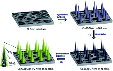
All solvents and chemicals were of reagent quality and used without further purification, which were obtained from Sinopharm Co. Sandwich structural Co3O4@C@PPy core–shell hybrids were synthesized via three steps as follows: firstly, the Co3O4 nanowires were grown on Ni foam via a typical hydrothermal method. Prior to the synthesis, the Ni foam substrate (3 cm × 2 cm × 0.1 cm) was rinsed with ethanol and water for 30 min each. The reaction solution was obtained by mixing 5 mmol Co(NO3)2·6H2O, 2.5 mmol CO(NH2)2 and 10 mmol (NH4)F in 30 mL of distilled water under stirring and then transferred into a 50 mL of Teflon-lined stainless steel autoclave liner. The washed Ni foam substrate was immersed into the reaction solution. The liner was maintained at 120 °C for 7 h and then cooled down to room temperature. After the reaction was over, the sample was taken out from the autoclave and washed by ultra-sonication in deionized water to remove the residual nanoparticle debris, then dried at 60 °C in an oven. Finally, to obtain Co3O4 nanowires, the precursor was annealed at 300 °C for 2 h. Secondly, to fabricate carbon-coated Co3O4 (Co3O4@C) nanowires, a piece of Ni foam substrate covered with Co3O4 nanowires was firstly immersed into a 0.02 M aqueous glucose solution for 24 h, and then transferred to a tubular furnace at 400 °C in Ar gas for 2 h. Thirdly, at a constant current density of 1.0 mA cm2, PPy film was electrochemically deposited on a piece of Ni foam with Co3O4@C in a three-electrode system included 0.15 M pyrrole and 0.02 M p-toluene sulfonate acid (TsOH) aqueous solution (working area: 1 × 1 cm2). The Pt foil and saturated calomel electrode (SCE) were served as the counter electrode and reference electrode, respectively. The deposition time ranging from 10 to 40 min were set to obtain different mass loadings (from 1.25 to 1.82 mg cm−2) of the Co3O4@C@PPy core–shell hybrids. After the deposition, Co3O4@C@PPy was immediately pulled out of the electrolyte and washed several times with deionized water to remove any salt residuals and loosely contacted oxides, and then dried in vacuum at 60 °C for 24 h.2.2 Assembling asymmetric supercapacitor
An asymmetric supercapacitor was assembled by using Co3O4@C@PPy as cathode and active carbon as anode, respectively. In details, an active carbon electrode was first prepared by mixing 80 wt% activated carbon, 10 wt% PTFE and 10 wt% NMF and casting the mixture onto a 1 cm2 nickel foam. The obtained negative electrode was pressed by the tablet machine and then dried in vacuum oven at 60 °C for overnight. Meanwhile, Co3O4@C@PPy cathode was soaked in a 2 M KOH aqueous electrolyte. As the separator, a piece of cellulose paper was sandwiched between both electrodes to assemble the full cell, in which 2 M KOH solution was filled as the electrolyte. The entire device was wrapped and sealed by parafilm.2.3 Materials characterization
The morphology of the samples was studied by using a scanning electron microscope (SEM, Ultra Plus, Carl Zeiss, Germany) and Transmission electron microscope (TEM, Tecnai G2 F20 S-TWIN, USA). The crystal structures were investigated by X-ray diffraction (XRD, X'Pert Pro, PANalytical B.V., Netherlands, Cu Kα irradiation; λ = 1.5418 Å) and X-ray photoelectron spectroscopy (XPS) spectrometer (ESCALAB 250Xi, Thermo Scientific Escalab, USA). The vibrational spectrum of the sample was collected by a Spectrum One Fourier transform infrared spectroscopy (FT-IR, Perkin-Elmer, USA). The mass loading of the hybrids was measured using a Sartorius BT 25 S semi-microbalance with a sensitivity of 0.01 mg.2.4 Electrochemical measurements
Electrochemical properties of electrodes were tested in a three-electrode system using multichannel electrochemical analyzer (VMP3, Bio-Logic-Science Instruments, France). The prepared sample, a Pt plate and Hg/HgO were used as the working electrode, counter electrode and the reference electrode, respectively. Electrochemical impedance spectra (EIS) were measured at open circuit potential with an amplitude of 5 mV in the frequency range of 0.01 Hz to 100 kHz on an electrochemical workstation (CHI660C, Chenhua, Shanghai). Charge storage behaviors of the ASC were investigated in two-electrode configuration. To investigate the electrochemical deposition process of PPy and the effect of loading on capacitance, the electrochemical performances of intermediate products were also studied with the different deposition time of 10 min, 20 min, 30 min and 40 min.The specific and areal capacitance of electrodes according to the galvanostatic discharge–charge profile is calculated based on eqn (1) and (2), respectively:
| Cs = IΔt/mΔV | (1) |
| Ca = IΔt/SΔV | (2) |
| E = CsΔV2/2 | (3) |
| P = E/Δt | (4) |
While the calculation of Cs, energy density and power density, we need to consider the total mass of electrode active materials (including both the negative and positive electrode materials). Herein, the mass of negative electrode was decided based on charge balance theory (Q+ = Q−):
| m− × C− × ΔV− = m+ × C+ × ΔV+ | (5) |
3. Results and discussion
3.1 Fabrication of sandwich structural Co3O4@C@PPy hybrids
Fig. 1 shows the fabrication process of sandwich structural Co3O4@C@PPy. Firstly, the Co3O4 nanowires were grown on Ni foam via a hydrothermal method. Secondly, the carbon-coated Co3O4 (Co3O4@C) nanowires were obtained via glucose carbonization at high temperature. Thirdly, PPy layer was electrochemically deposited on the surface of Co3O4@C NWs with a constant current density, in which the pyrrole monomer and TsOH anions were anchored to surfaces of carbon layer decorated Co3O4@C via π–π interactions between aromatic rings of pyrrole as well as of TsOH with the sp2 carbon.22 These π–π interactions provide sufficient nucleation sites for the growth of PPy films.To study the crystal structure and composition of Co3O4@C@PPy core–shell hybrids, we conducted XRD and FT-IR measurements for the prepared Co3O4@C@PPy, as well as similarly prepared Co3O4 and Co3O4@C (Fig. 2). In order to preclude the strong diffraction impact of the Ni foam substrate on the XRD peak signals, the sample powders were scratched from the Ni foam for XRD analysis. All the diffraction peaks collected in the XRD patterns of the three samples can be indexed to Co3O4 (JCPDS no. 43-1003). According to the XRD patterns in Fig. 2a, The carbon may be amorphous in both of Co3O4@C and Co3O4@C@PPy, because there is no other diffraction can be detected in the XRD patterns of Co3O4@C except the diffractions of the Co3O4. In the patterns of Co3O4@C@PPy, the peak at 26.2° is corresponding to amorphous PPy. Fig. 2b displays FT-IR spectra of Co3O4, Co3O4@C and Co3O4@C@PPy. We can observe that typical vibrations of Co3O4 exist in the spectra of each sample. The characteristic Co–O stretching vibrations of Co3O4 appear at about 557 and 658 cm−1.25 For Co3O4@C@PPy, the anti-symmetrical and symmetrical vibrations of the pyrrole ring can be seen at 1545 and 1400 cm−1. The stretching vibration of the sulfonic group in doped TsO− are at 1285 cm−1, and stretching vibration of the C–N bond in PPy appear at 1207 cm−1.22 The bands at 920 and 797 cm−1 can be ascribed to polymerized pyrrole.31,34 The absorption band at 1078 is attributed to the C–H deformation vibration. Due to structure water, the vibration at 1630 cm−1 can be seen in the spectra of Co3O4@C@PPy.30 By analyzing the FT-IR results, the presence of PPy in the Co3O4@C@PPy can be confirmed.
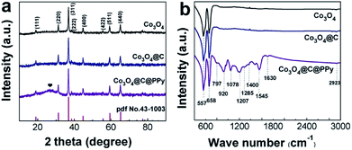 | ||
| Fig. 2 (a) XRD patterns collected for Co3O4, Co3O4@C and Co3O4@C@PPy; (b) FT-IR spectra of Co3O4, Co3O4@C and Co3O4@C@PPy. | ||
In Fig. 3, the overall morphologies of the Co3O4, Co3O4@C and Co3O4@C@PPy after the hydrothermal growth are displayed. As can be seen, the Co3O4, Co3O4@C and Co3O4@C@PPy are separated from each other to form many nanoclusters composed by nanowires. The SEM images with high magnification (inset of Fig. 3a–c) suggest that the Co3O4 nanowires are tightly and uniformly covered with amorphous carbon and PPy film, forming a sandwich core–shell structure with a greatly enlarged working surface area, beneficial for electrolyte penetration and fast electron conduction. From the side view in Fig. 3d, the height of Co3O4@C@PPy hybrid is about 4 μm.
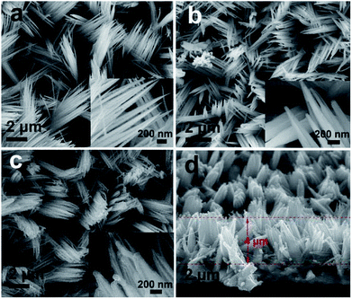 | ||
| Fig. 3 The top view SEM images of (a) Co3O4, (b) Co3O4@C, (c) Co3O4@C@PPy. Insets are magnified SEM images of samples; cross-sectional SEM image of (d) Co3O4@C@PPy from the side view. | ||
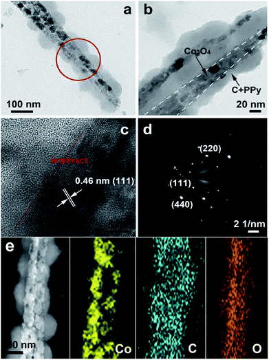
As shown in Fig. 4a–b, the sandwich structure of Co3O4@C@PPy hybrids can be further verified by the typical TEM analysis. The Co3O4 nanowire is uniformly wrapped by thin carbon and PPy layer (5–20 nm). Fig. 4c shows the HRTEM image of Co3O4@C@PPy at the interface, indicating that the clear lattice fringes with an interspacing of 0.46 nm is corresponding to the (111) planes of cubic-phase Co3O4. The well-defined diffraction pattern in Fig. 4d demonstrates that the Co3O4@C@PPy is monocrystalline. In comparison, the TEM images in Fig. S1† show that the prepared Co3O4 nanowires and Co3O4@C. As the Co3O4@C nanowire is derived from the Co3O4 nanowire via glucose carbonization, the central and the surrounding sections in Co3O4@C were different in Fig. S1d.† Moreover, we carried out the Energy Dispersive X-ray spectrum (EDX) test to evaluate the content of Co3O4@C@PPy. The EDX spectrum in Fig. S2† indicates cobalt, oxygen, nitrogen, nickel and carbon elements are detected in the Co3O4@C@PPy hybrid. In the EDX spectra, the N signal came from N–H bond in the PPy backbone, while the Co signal originated from Co3O4. Thus, the amount ratio between Co3O4 and PPy can be calculated according to the Co/N peak intensity ratio. The ratio of cobalt oxide to PPy is 2.3![[thin space (1/6-em)]](https://www.rsc.org/images/entities/char_2009.gif) :
:![[thin space (1/6-em)]](https://www.rsc.org/images/entities/char_2009.gif) 1. The corresponding elemental mapping in Fig. 4e displays that the elements of Co and O from cobalt oxide, as well as carbon from PPy and amorphous carbon are uniformly distributed within the whole nanowire of Co3O4@C@PPy, further suggesting the presence of the sandwich structural Co3O4@C@PPy.
1. The corresponding elemental mapping in Fig. 4e displays that the elements of Co and O from cobalt oxide, as well as carbon from PPy and amorphous carbon are uniformly distributed within the whole nanowire of Co3O4@C@PPy, further suggesting the presence of the sandwich structural Co3O4@C@PPy.
For the Co3O4@C@PPy hybrids, the compositions were further analyzed by XPS. A full survey scan spectrum is shown in Fig. S3,† indicating the presence of Co, O, C, N and Ni element. In Fig. 5a, the Co 2p core level spectra are fitted. Both of the dominant peaks at 795.3 eV and 779.8 eV can be disassembled into four synthetic peaks, indicating that the cobalt existed in mixed oxidation states. The synthetic peaks located at 779.5 and 794.9 eV in the spectra is corresponding to Co3+. While the peaks at 781.2 and 796.6 eV are related to Co2+.24 Whereas The absence of weak shakeup satellite peaks at around 785.4 eV and 803.8 eV in the Co 2p spectra further suggests the formation of the Co3O4 phase.49–51 The N 1s core level spectra are given in Fig. 5b. The fitting peaks at 402.0, 399.9 and 398.5 eV in the spectra can be attributed to –NH+–, –NH– and ![[double bond, length as m-dash]](https://www.rsc.org/images/entities/char_e001.gif) N– in the pyrrole ring, respectively.27 The peaks of O 1s spectrum are presented in Fig. 5c, in which one peak centered at 529.6 eV is related to the O2− forming oxides with Co and the other at 531.4 eV is attributed to the H
N– in the pyrrole ring, respectively.27 The peaks of O 1s spectrum are presented in Fig. 5c, in which one peak centered at 529.6 eV is related to the O2− forming oxides with Co and the other at 531.4 eV is attributed to the H![[double bond, length as m-dash]](https://www.rsc.org/images/entities/char_e001.gif) O bonds of the surface hydroxyl groups.26 Fig. 5d displays the C 1s spectrum of the sample. The prominent peak appeared at 284.8 eV is assigned to sp2-hybridized carbon. Another two peaks appeared at approximately 285.6 eV and 288.4 eV, suggesting the presence of C–O and C
O bonds of the surface hydroxyl groups.26 Fig. 5d displays the C 1s spectrum of the sample. The prominent peak appeared at 284.8 eV is assigned to sp2-hybridized carbon. Another two peaks appeared at approximately 285.6 eV and 288.4 eV, suggesting the presence of C–O and C![[double bond, length as m-dash]](https://www.rsc.org/images/entities/char_e001.gif) O bonds. The strong signal of elemental carbon should not only arise from polypyrrole carbon, but also from the carbon reduced from glucose. These results further confirmed that the shell is composed of amorphous carbon layers.
O bonds. The strong signal of elemental carbon should not only arise from polypyrrole carbon, but also from the carbon reduced from glucose. These results further confirmed that the shell is composed of amorphous carbon layers.
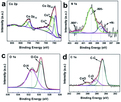 | ||
| Fig. 5 (a) Co 2p XPS core level spectra, (b) N 1s XPS core level spectra, (c) O 1s XPS core level spectra and (d) C 1s XPS core level spectra of Co3O4@C@PPy. | ||
3.2 Influence of electropolymerization time on properties of the Co3O4@C@PPy
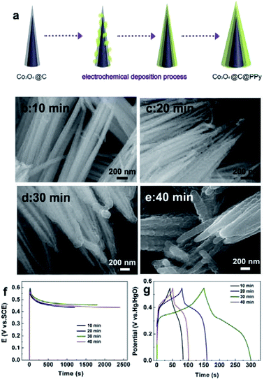
To study the influence of electropolymerization time of PPy on the morphology and properties, we have also designed different polymerization times to obtain hybrids with different thickness of PPy layer. Electropolymerization of pyrrole was conducted at different electropolymerization times from 10 to 40 min.Fig. 6a shows the electrochemical deposition process of pyrrole on Co3O4@C nanowires. As shown in Fig. 6b, in Co3O4@C@PPy afforded from 10 min, the PPy film also intimately covered on surfaces of Co3O4@C NWs, with many small aggregates. As the polymerization time increased, the thickness of the PPy layers increased and eventually formed a dense layer (Fig. 6b–e). The chronopotentiometric curves of pyrrole polymerization at electropolymerization times ranging from 10 to 40 min are displayed in Fig. 6f. The electrochemical deposition process can be divided to three stages. In the first stage, there appeared a rapid potential increase related to double-layer charging and pyrrole oxidation. A moderate potential increase in the following stage corresponds to nucleation of the polymer. Electropolymerization related to PPy film growth ended in stage III.21,22,27 It can be seen that the PPy films with different deposition times displayed similar potential change of their chronopotentiometric curves, demonstrating their similar growth stage and formation mechanism. The Fig. 6g compares the galvanostatic charge–discharge profiles of hybrids obtained at the deposition time of 10, 20, 30, 40 min at the same current density of 10 mA cm−2. As can be seen, Co3O4@C@PPy hybrids (30 min) displayed longer discharge time than other samples, indicating its higher electroactivity and larger capacitance. The lower specific capacitances of hybrids of 10 min and 20 min, compared with 30 min, can be ascribed to the incomplete and inconsecutive PPy film. Especially in the 10 min sample, the PPy have just aggregated into small particles, which have not formed a good electrical conductivity network to promote fast electron transmission between internal active materials and electrode surface. Thus, the effective contact of encapsulated metal oxides with electrolyte ion was blocked by thicker PPy film, leading to the capacitance loss of partial Co3O4. Thus, the hybrids with comparatively larger proportion of the polymer exhibited lower specific capacitance than other hybrids. Hence, the suitable thickness and mass loading of PPy film controlled by electropolymerization time can facilitate obvious improved property of sandwich structural Co3O4@C@PPy hybrids.
3.3 Electrochemical properties of Co3O4@C@PPy
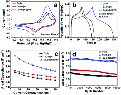
The electrochemical performances of Co3O4 hybrids were studied in 2 M KOH aqueous electrolyte. Among the samples, Co3O4@C@PPy at the deposition time of 30 min delivered the best electrochemical property. As shown in cyclic voltammetry (CV) profiles (Fig. 7a), the pristine Co3O4 electrode exhibits a pair of current peaks at 0.32/0.46 V ascribed to the redox reaction of Co3+/Co4+.25,26 After carbon film attachment on the surface of Co3O4, CV curve of Co3O4@C electrode is expanded slightly. The redox peaks of Co3O4@C shifted slightly due to the presence of electric double-layer amorphous carbon. In the case of Co3O4@C@PPy hybrid, besides redox peaks characteristic of Co3O4, the current response becomes significantly higher, leading to a higher specific capacitance. CV curves presented in Fig. S4† of Co3O4, Co3O4@C and Co3O4@C@PPy electrode were also collected at various scan rates. Based on the CV curves, at scan rates of 5 to 100 mV s−1, the peak shapes do not significantly change, evidencing a reversible electrochemistry and the ideal pseudocapacitive performance. A comparison of the galvanostatic charge–discharge curves of the pure Co3O4, Co3O4@C, and Co3O4@C@PPy hybrids is shown in Fig. 7b. The pristine Co3O4 electrode exhibits an areal capacitance of 1.31 F cm−2 at the current density of 10 mA cm−2. The charge–discharge curve of the Co3O4@C hybrids is similar to that of Co3O4. Although the electrochemical performance is improved (1.48 F cm−2 at 10 mA cm−2), the result is not ideal because the loading mass of the carbon layer is so small (0.23 mg) and the intrinsic capacitance of carbon is far below that of Co3O4. In comparison to the other two electrodes, the sandwich structural Co3O4@C@PPy hybrids possess longer discharging time, corresponding to the CV results. At the same current, the areal capacitance of Co3O4@C@PPy hybrid electrode reaches to 2.71 F cm−2 (1663 F g−1 at 6.1 A g−1), which reveals the advantage of the pseudocapacitive materials with the sandwich core–shell structure for high capacitance. In Fig. 7c, the Co3O4@C@PPy showed a good rate capability. Even at a larger current density of 50 mA cm−2 (31 A g−1), a high capacitance of 1.57 F cm−2 (963 F g−1) could be maintained. When current density increased 10 times from 5 to 50 mA cm−2, the capacitance of Co3O4@C@PPy could retain 51.7%, and pristine Co3O4 can retain 46.8%. The sandwich core–shell structure can promote ion transportation and ensure the effect contact of various electroactive materials with electrolyte ion for charge storage. Rapid electron transfer between core and shell can further enhance rate capability of the hybrid. In particular, Co3O4@C exhibited better rate capacity (60.1%) than the Co3O4@C@PPy, which could be ascribed to the ion-exchange between anions doped in polypyrrole film and OH− ion in the alkaline electrolyte during charge–discharge process at high current, leading to the decay of electrical conductivity of Co3O4@C@PPy.14,44 We also conducted EIS measurements to evaluate the electrical conductivity of electrodes. The Nyquist plots of Co3O4, Co3O4@C and Co3O4@C@PPy are shown in Fig. S5.† Co3O4@C@PPy showed steeper line than Co3O4 and Co3O4@C in the low frequency domain, demonstrating its better ion diffusion kinetics.34 All of samples displayed similar combined series resistances (Rs), demonstrating the enlarged loading and multilayer modification didn't affect the intrinsic resistance dramatically. Based on semicircles in the high frequency, Co3O4@C@PPy and Co3O4@C displayed lower charge transfer resistance (Rct) than pristine Co3O4, indicating the coating shell can offer a fast charge transfer channel from the inter core to the electrode surface and effectively improve the conductivity of the Co3O4 electrode.The stability was studied by prolonged galvanostatic charge–discharge cycles at current density of 25 mA cm−2 (Fig. 7d). After 10![[thin space (1/6-em)]](https://www.rsc.org/images/entities/char_2009.gif) 000 charge–discharge cycles, Co3O4 and Co3O4@C can retain 69.2% and 71.7% of their initial capacitances, respectively. However, the Co3O4@C@PPy maintain 86.4% of the initial capacitance, showing its improved cyclic stability. Notably, the stability of Co3O4@C@PPy is better than our previous in situ chemical polymerized Co3O4@PPy composite (77.8% retention for 5000 cycles),25 showing the effectiveness of the carbon layer. The intermediary carbon layer provides more protection against volume expansion and structural damage of metal oxides during charge–discharge process, and a larger effective reaction area with high conductivity for PPy. Because of the low conductivity of the Co3O4 nanowires and a smaller effective reaction area, the electrochemical performance of PPy on the Co3O4@PPy composite is not fully reflected. In summary, the performance advantages of the sandwich structural Co3O4@C@PPy include the following several factors: (1) Co3O4, as a good pseudocapacitive material, directly grown on Ni foam as scaffold could provide active sites for the faradic redox reaction. (2) As the “shell”, the coated carbon and PPy layer can not only enlarge the accessible surface area and facilitate electrolyte ion penetration, but also improve electronic conductivity to ensure more effective charge transfer. Besides, the “shell” is so thin that it would not hinder full participation of the Co3O4 NWs “core” in the Faraday redox reaction. (3) The sandwiched carbon layer could serve as a transition could not only confine PPy growth reaction on the nanowire surface, but also provides electron “superhighways” inside the electrode.27 (4) During the fabrication of the integrated electrode, there is no any binder or conducting additive, avoiding “dead” volume in the electroactive materials.
000 charge–discharge cycles, Co3O4 and Co3O4@C can retain 69.2% and 71.7% of their initial capacitances, respectively. However, the Co3O4@C@PPy maintain 86.4% of the initial capacitance, showing its improved cyclic stability. Notably, the stability of Co3O4@C@PPy is better than our previous in situ chemical polymerized Co3O4@PPy composite (77.8% retention for 5000 cycles),25 showing the effectiveness of the carbon layer. The intermediary carbon layer provides more protection against volume expansion and structural damage of metal oxides during charge–discharge process, and a larger effective reaction area with high conductivity for PPy. Because of the low conductivity of the Co3O4 nanowires and a smaller effective reaction area, the electrochemical performance of PPy on the Co3O4@PPy composite is not fully reflected. In summary, the performance advantages of the sandwich structural Co3O4@C@PPy include the following several factors: (1) Co3O4, as a good pseudocapacitive material, directly grown on Ni foam as scaffold could provide active sites for the faradic redox reaction. (2) As the “shell”, the coated carbon and PPy layer can not only enlarge the accessible surface area and facilitate electrolyte ion penetration, but also improve electronic conductivity to ensure more effective charge transfer. Besides, the “shell” is so thin that it would not hinder full participation of the Co3O4 NWs “core” in the Faraday redox reaction. (3) The sandwiched carbon layer could serve as a transition could not only confine PPy growth reaction on the nanowire surface, but also provides electron “superhighways” inside the electrode.27 (4) During the fabrication of the integrated electrode, there is no any binder or conducting additive, avoiding “dead” volume in the electroactive materials.
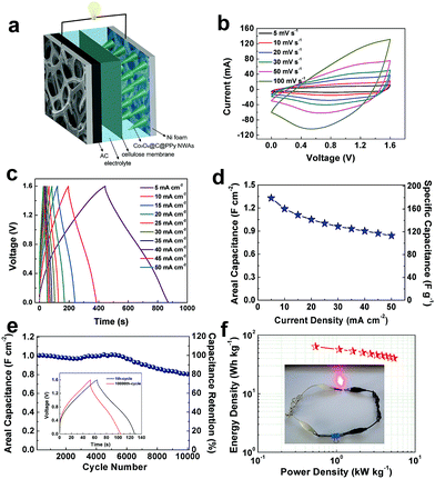
As schematic illustration shown in Fig. 8a, an asymmetric supercapacitor of Co3O4@C@PPy//active carbon was assembled by Co3O4@C@PPy and active carbon coated and 2 M KOH solution as electrolyte to study the application of the Co3O4@C@PPy hybrids. To explore the mass loading and areal capacitance contributed from active carbon in the device, paralleled charge–discharge experiments were conducted. The CV curves in Fig. S6† in the potential ranges of 0–0.6 and −1.0 to 0 V show the charge balance stored in the anode and cathode. A series of CV measurements of the asymmetric supercapacitor with different cell voltages varying from 0.6 V to 1.6 V were taken as shown in Fig. S7.† With the voltage increased to 1.6 V, larger peak current can be seen, which indicating that more faradic reactions occurred and the pseudocapacitive characteristics of the device originate from the positive electrode. For the proportional energy density, an operating voltage of 1.6 V is chosen for further investigation of electrochemical property of the device. In Fig. 8b, the CV profiles obtained at different scan rates indicate good electrochemical capacitive behavior. The charge–discharge profiles of the ASC at different current densities are shown in Fig. 8c. This device delivered a remarkable capacitance of 1.33 F cm−2 (179 F g−1) at a current density of 5 mA cm−2 (0.67 A g−1). As the current density increases 10 times, the device can achieve a good rate capability of 63.2% (Fig. 8d). The stability of Co3O4@C@PPy//AC was investigated by constant current at 25 mA cm−2 (Fig. 8e). After 10![[thin space (1/6-em)]](https://www.rsc.org/images/entities/char_2009.gif) 000 galvanostatic charge–discharge cycles, the ASC exhibited a good cycling stability with 80.1% retention of its initial capacitance. The energy density and power density of Co3O4@C@PPy can be calculated by eqn (3) and eqn (4), as shown in the Ragone plot of Fig. 8f. Owing to the high specific capacitance and wide potential window, the device exhibits a high energy density of 63.64 W h kg−1 at a power density of 0.54 kW kg−1, illustrating its excellent energy storage capacity. The result is essentially better than or comparable to recent reported works about Co3O4 combined with metal oxides or other organic compounds. For example, the ternary composite of AC//Co3O4@PPy@MnO2 device can deliver an energy density of 34.3 W h kg−1 at 80 W kg−1.27 At a power density of 266.5 W kg−1, Co3O4@Au-PPy NWAs//AC asymmetric cell delivers a maximum energy density of 46.2 W h kg−1.26 The hybrid nanocomposite of Co3O4@polypyrrole/MWCNT displays capacitive behavior with an energy density 84.58 W h kg−1 at 1500 W kg−1.35 The energy density of the asymmetric supercapacitor based on Co3O4 nanowires combined with carbon aerogel can reach to 10.44 W h kg−1 at a power density of 7.5 kW kg−1.11 A device based on CoO/Co3O4 can deliver an energy density of 10.52 W h kg−1 at 140 W kg−1.48 At a power density of 375 W kg−1, the asymmetric supercapacitor assembled with N-doped carbon aerogel/Co3O4 electrodes possess a maximum energy density of 33.43 W h kg−1.5
000 galvanostatic charge–discharge cycles, the ASC exhibited a good cycling stability with 80.1% retention of its initial capacitance. The energy density and power density of Co3O4@C@PPy can be calculated by eqn (3) and eqn (4), as shown in the Ragone plot of Fig. 8f. Owing to the high specific capacitance and wide potential window, the device exhibits a high energy density of 63.64 W h kg−1 at a power density of 0.54 kW kg−1, illustrating its excellent energy storage capacity. The result is essentially better than or comparable to recent reported works about Co3O4 combined with metal oxides or other organic compounds. For example, the ternary composite of AC//Co3O4@PPy@MnO2 device can deliver an energy density of 34.3 W h kg−1 at 80 W kg−1.27 At a power density of 266.5 W kg−1, Co3O4@Au-PPy NWAs//AC asymmetric cell delivers a maximum energy density of 46.2 W h kg−1.26 The hybrid nanocomposite of Co3O4@polypyrrole/MWCNT displays capacitive behavior with an energy density 84.58 W h kg−1 at 1500 W kg−1.35 The energy density of the asymmetric supercapacitor based on Co3O4 nanowires combined with carbon aerogel can reach to 10.44 W h kg−1 at a power density of 7.5 kW kg−1.11 A device based on CoO/Co3O4 can deliver an energy density of 10.52 W h kg−1 at 140 W kg−1.48 At a power density of 375 W kg−1, the asymmetric supercapacitor assembled with N-doped carbon aerogel/Co3O4 electrodes possess a maximum energy density of 33.43 W h kg−1.5
4. Conclusions
In summary, the high-performance pseudocapacitive electrode of sandwich structural Co3O4@C@PPy was constructed by hydrothermal synthesis of Co3O4 coated with amorphous carbon and electropolymerization of pyrrole on Ni foam. Benefiting from the facilitated ion diffusion and fast electron transportation through the sandwich structural core–shell structures consisted of Co3O4 nanowire core, high-conductive PPy shell and embedded amorphous carbon, the fabricated Co3O4@C@PPy showed improved rate capability and higher areal capacitance. Compared to similarly prepared Co3O4 nanowires (69.2% retention after 10![[thin space (1/6-em)]](https://www.rsc.org/images/entities/char_2009.gif) 000 cycles), the Co3O4@C@PPy hybrid also displayed a good cyclic stability with 86.4% capacitance retention after 10
000 cycles), the Co3O4@C@PPy hybrid also displayed a good cyclic stability with 86.4% capacitance retention after 10![[thin space (1/6-em)]](https://www.rsc.org/images/entities/char_2009.gif) 000 charge–discharge cycles. The asymmetric device based on Co3O4@C@PPy can deliver a high energy density, meanwhile it can retain 80.1% of its capacitance after 10
000 charge–discharge cycles. The asymmetric device based on Co3O4@C@PPy can deliver a high energy density, meanwhile it can retain 80.1% of its capacitance after 10![[thin space (1/6-em)]](https://www.rsc.org/images/entities/char_2009.gif) 000 cycles. This core–shell hybrid formation demonstrates a successful layer-by-layer coating process and fabricates an ideal Co3O4 based capacitive material for energy storage.
000 cycles. This core–shell hybrid formation demonstrates a successful layer-by-layer coating process and fabricates an ideal Co3O4 based capacitive material for energy storage.
Conflicts of interest
There are no conflicts to declare.Acknowledgements
The work was supported by the National Natural Science Foundation of China (Grant No. 51604067 and Grant No. 21273029) and the China Postdoctoral Science Foundation (Grant no. 2015M580228).References
- H. Q. Fan, L. X. Quan, M. Q. Yuan, S. S. Zhu, K. Wang, Y. Zhong, L. Chang, H. B. Shao, J. M. Wang, J. Q. Zhang and C. Cao, Electrochim. Acta, 2016, 188, 222–229 CrossRef CAS.
- G. Godillot, P. L. Taberna, B. Daffos, P. Simon, C. Delmas and L. Guerlou-Demourgues, J. Power Sources, 2016, 331, 277–284 CrossRef CAS.
- Q. Q. Ke, C. H. Tang, Z. C. Yang, M. R. Zheng, L. Mao, H. J. Liu and J. Wang, Electrochim. Acta, 2015, 163, 9–15 CrossRef CAS.
- J. C. Liu, Y. J. Xu, X. J. Ma, J. K. Feng, Y. T. Qian and S. L. Xiong, Nano Energy, 2014, 7, 52–62 CrossRef CAS.
- G. L. Sun, L. Y. Ma, J. B. Ran, X. Y. Shen and H. Tong, J. Mater. Chem. A, 2016, 4, 9542–9554 RSC.
- N. Wang, Q. L. Liu, D. M. Kang, J. J. Gu, W. Zhang and D. Zhang, ACS Appl. Mater. Interfaces, 2016, 8, 16035–16044 CrossRef CAS PubMed.
- J. Jiang, W. Shi, S. Song, Q. L. Hao, W. Q. Fan, X. F. Xia, X. Zhang, Q. Wang, C. B. Liu and D. Yan, J. Power Sources, 2014, 248, 1281–1289 CrossRef CAS.
- J. Xu, W. Zhang, Y. Chen, H. Fan, D. Su and G. Wang, J. Mater. Chem. A, 2018, 6, 2797–2807 RSC.
- W. Xia, R. Q. Zou, L. An, D. G. Xia and S. J. Guo, Energy Environ. Sci., 2015, 8, 568–576 RSC.
- D. Z. Kong, C. W. Cheng, Y. Wang, J. I. Wong, Y. P. Yang and H. Y. Yang, J. Mater. Chem. A, 2015, 3, 16150–16161 RSC.
- W. W. Liu, X. Li, M. H. Zhu and X. He, J. Power Sources, 2015, 282, 179–186 CrossRef CAS.
- C. Zhang, J. Xiao, X. L. Lv, L. H. Qian, S. L. Yuan, S. Wang and P. X. Lei, J. Mater. Chem. A, 2016, 4, 16516–16523 RSC.
- Y. Q. Zou, I. A. Kinloch and R. A. W. Dryfe, ACS Appl. Mater. Interfaces, 2015, 7, 22831–22838 CrossRef CAS PubMed.
- H. J. Yan, J. W. Bai, M. R. Liao, Y. He, Q. Liu, J. Y. Liu, H. S. Zhang, Z. S. Li and J. Wang, Eur. J. Inorg. Chem., 2017, 1143–1152 CrossRef CAS.
- K. B. Wang, M. B. Zheng, X. B. Shi, Z. X. Lin, H. J. Wang and Y. N. Lu, Chem. Eng. J., 2015, 266, 141–147 CrossRef CAS.
- M. B. Durukan, R. Yuksel and H. E. Unalan, Electrochim. Acta, 2016, 222, 1475–1482 CrossRef CAS.
- Z. W. Mao, M. Zhou, K. L. Wang, W. Wang, H. W. Tao and K. Jiang, RSC Adv., 2017, 7, 23122–23126 RSC.
- J. S. Lee, D. H. Shin and J. Jang, Energy Environ. Sci., 2015, 8, 3030–3039 RSC.
- C. Yang, L. L. Zhang, N. T. Hu, Z. Yang, H. Wei and Y. F. Zhang, J. Power Sources, 2016, 302, 39–45 CrossRef CAS.
- Y. Yesi, I. Shown, A. Ganguly, T. T. Ngo, L. C. Chen and K. H. Chen, ChemSusChem, 2016, 9, 370–378 CrossRef CAS PubMed.
- L. Zhan, H. B. Chen, J. Q. Fang, S. Q. Wang, L. X. Ding, Z. Li, P. J. Ashman and H. H. Wang, Electrochim. Acta, 2016, 209, 192–200 CrossRef CAS.
- Z. H. Huang, Y. Song, X. X. Xu and X. X. Liu, ACS Appl. Mater. Interfaces, 2015, 7, 25506–25513 CrossRef CAS PubMed.
- Z. Y. Hai, L. B. Gao, Q. Zhang, H. Y. Xu, D. F. Cui, Z. X. Zhang, D. Tsoukalas, J. Tang, S. B. Yan and C. Y. Xue, Appl. Surf. Sci., 2016, 361, 57–62 CrossRef CAS.
- C. Zhou, Y. W. Zhang, Y. Y. Li and J. P. Liu, Nano Lett., 2013, 13, 2078–2085 CrossRef CAS PubMed.
- D. Guo, M. Y. Zhang, Z. Chen and X. X. Liu, Mater. Res. Bull., 2017, 96, 463–470 CrossRef CAS.
- W. Hong, J. Q. Wang, Z. P. Li and S. R. Yang, J. Mater. Chem. A, 2015, 3, 2535–2540 RSC.
- L. J. Han, P. Y. Tang and L. Zhang, Nano Energy, 2014, 7, 42–51 CrossRef CAS.
- F. M. Wang, X. Y. Zhan, Z. Z. Cheng, Z. X. Wang, Q. S. Wang, K. Xu, M. Safdar and J. He, Small, 2015, 11, 749–755 CrossRef CAS PubMed.
- Y. Song, T. Y. Liu, X. X. Xu, D. Y. Feng, Y. Li and X. X. Liu, Adv. Funct. Mater., 2015, 25, 4626–4632 CrossRef CAS.
- Y. Song, J. L. Xu and X. X. Liu, J. Power Sources, 2014, 249, 48–58 CrossRef CAS.
- K. B. Xu, X. J. Huang, Q. Liu, R. J. Zou, W. Y. Li, X. J. Liu, S. J. Li, J. M. Yang and J. Q. Hu, J. Mater. Chem. A, 2014, 2, 16731–16739 RSC.
- H. Fan, N. Zhao, H. Wang, J. Xu and F. Pan, J. Mater. Chem. A, 2014, 2, 12340–12347 RSC.
- X. Peng, K. Huo, J. Fu, X. Zhang, B. Gao and P. K. Chu, Chem. Commun., 2013, 49, 10172–10174 RSC.
- B. Wang, X. Y. He, H. P. Li, Q. Liu, J. Wang, L. Yu, H. J. Yan, Z. S. Lia and P. Wang, J. Mater. Chem. A, 2014, 2, 12968–12973 RSC.
- S. Ramesh, Y. Haldorai, H. S. Kim and J. H. Kim, RSC Adv., 2017, 7, 36833–36843 RSC.
- T. Deng, W. Zhang, O. Arcelus, J. G. Kim, J. Carrasco, S. J. Yoo, W. T. Zheng, J. F. Wang, H. W. Tian, H. B. Zhang, X. Q. Cui and T. Rojo, Nat. Commun., 2016, 8, 15194–15202 CrossRef PubMed.
- Y. Q. Li, X. M. Shi, X. Y. Lang, Z. Wen, J. C. Li and Q. Jiang, Adv. Funct. Mater., 2016, 26, 1830–1839 CrossRef CAS.
- X. Y. Liu, Y. Q. Gao and G. W. Yang, Nanoscale, 2016, 8, 4227–4235 RSC.
- W. Xu, J. H. Chen, M. H. Yu, Y. X. Zeng, Y. B. Long, X. H. Lu and Y. X. Tong, J. Mater. Chem. A, 2016, 4, 10779–10785 RSC.
- G. H. Cheng, C. H. Si, J. Zhang, Y. Wang, W. F. Yang, C. Q. Dong and Z. H. Zhang, J. Power Sources, 2016, 312, 184–191 CrossRef CAS.
- L. Jiang, X. Lu, C. Xie, G. Wan, H. Zhang and Y. Tang, J. Phys. Chem. C, 2015, 119, 3903–3910 CrossRef CAS.
- Q. Liao, N. Li, S. Jin, G. Yang and C. Wang, ACS Nano, 2015, 9, 5310–5317 CrossRef CAS PubMed.
- Q. Yang, Z. Lu, T. Li, X. Sun and J. Liu, Nano Energy, 2014, 7, 170–178 CrossRef CAS.
- B. Liu, D. Z. Kong, J. Zhang, Y. Wang, T. P. Chen, C. W. Cheng and H. Y. Yang, J. Mater. Chem. A, 2016, 4, 3287–3296 RSC.
- A. K. Singh, D. Sarkar, K. Karmakar, K. Mandal and G. G. Khan, ACS Appl. Mater. Interfaces, 2016, 8, 20786–20792 CrossRef CAS PubMed.
- X. Lu, T. Zhai, X. Zhang, Y. Shen, L. Yuan, B. Hu and Z. L. Wang, Adv. Mater., 2012, 24, 938–944 CrossRef CAS PubMed.
- H. Xia, D. Zhu, Z. Luo, Y. Yu, X. Shi, G. Yuan and J. Xie, Sci. Rep., 2013, 3, 2978 CrossRef PubMed.
- M. J. Pang, G. H. Long, S. Jiang, Y. Ji, W. Han, B. Wang, X. L. Liu, Y. L. Xi, D. X. Wang and F. Z. Xu, Chem. Eng. J., 2015, 280, 377–384 CrossRef CAS.
- J. Yang, K. Walczak, E. Anzenberg, F. M. Toma, G. Yuan, J. Beeman, A. Schwartzberg, Y. Lin, M. Hettick, A. Javey, J. W. Ager, J. Yano, H. Frei and I. D. Sharp, J. Am. Chem. Soc., 2014, 136, 6191–6194 CrossRef CAS PubMed.
- L. Liao, Q. Zhang, Z. Su, Z. Zhao, Y. Wang, Y. Li, X. Lu, D. Wei, G. Feng, Q. Yu, X. Cai, J. Zhao, Z. Ren, H. Fang, F. Robles-Hernandez, S. Baldelli and J. Bao, Nat. Nanotechnol., 2014, 9, 69–73 CrossRef CAS PubMed.
- M. Qorbani, N. Naseri and A. Z. Moshfegh, ACS Appl. Mater. Interfaces, 2015, 7, 11172–11179 CrossRef CAS PubMed.
Footnote |
| † Electronic supplementary information (ESI) available. See DOI: 10.1039/c8ra07032f |
| This journal is © The Royal Society of Chemistry 2018 |

