DOI:
10.1039/C8RA06852F
(Paper)
RSC Adv., 2018,
8, 34182-34191
Electronic and thermal spin effect of molecular nanowires between graphene electrodes
Received
16th August 2018
, Accepted 9th September 2018
First published on 4th October 2018
Abstract
Based on the first-principles method, the electronic spin transport properties of terphenyl molecule bridging in zigzag graphene nanoribbon (ZGNR) electrodes with three connecting linkages were investigated, including dangling, heptagon, and pentagon-linkages. For the pentagon-linkage system, we observed a perfect spin filtering effect in the parallel (P) configuration (at almost 100% spin polarization), with the heptagon-linkages system following next (85–95% spin polarization), however, the spin filtering effect is almost negligible for the dangling-linkages system. In the antiparallel (AP) configuration, the pentagon- and heptagon-linkage systems also showed a high spin filtering effect. The terphenyl molecule was then replaced by carbon chains based on the pentagon-linkages, and these devices also show a perfect spin filtering effect (100% spin polarization). Finally, the thermally induced spin transport for the carbon chains model with pentagon-linkages was explored, and this system exhibits almost 100% thermal spin polarization.
1. Introduction
Research on graphene and the corresponding low-dimensional graphene nanoribbons (GNRs) has become more and more important in nanoscience and nanotechnology,1–4 because of their predominant properties, including a high carrier mobility, edge magnetic state, and sensitivity for gate adjustment. Graphene also shows long spin-scattering times and is expected to be a good candidate for spintronic components.5,6 The nanoribbons can be obtained by cutting a graphene sheet along a certain direction, and the electronic or magnetic properties can be turned by various approaches,7,8 such as doping chemical elements,9,10 introducing defects,11,12 and applying an external electric or magnetic field.13,14 In graphene nanoribbons with zigzag-shaped edges, magnetic exchange interactions between the spin states at the edges favor antiparallel (antiferromagnetic) configurations. However, the strength of this interaction decreases rapidly as the width, W, of the nanoribbon increases. For zigzag graphene nanoribbons (ZGNRs), the stability of two parallel ferromagnetic configurations may depend on the condition of an external magnetic field.15 Some intrinsic topological defects are commonly found due to the growth process of graphene, therefore, multiple domains will appear inside graphene,16,17 such as pentagon–heptagon (5–7), octagonal and paired pentagonal (558) defects. These defects are one-dimensional topological line defects which can be observed using a scanning tunneling microscope (STM). Previous research show that ZGNRs with an extended 558-defect can exhibit a spin polarization,18 but the spin-filtering efficiency is less than 80%. When ZGNRs and armchair graphene nanoribbons (AGNR) are connected by pentagon–heptagon (5–7) defect-lines, different spin polarizations can be obtained. More interesting, defect-line types obviously affect the polarization efficiency.19 However, the departmental influence of pentagon–heptagon (5–7) defects on the spin transport properties are not clear. For single molecules attached between two electrodes, interference effects originating from different anchoring groups or positions clearly affect the transport of electrons.20 For example, a polyacetylene chain bridging the graphene sublattice of ZGNRs may lead to two bonding arrangements, and metallic or semiconducting systems can be obtained owing to the local coupling.21 Moreover, spin caloritronics are attracting growing interest, as they combine the advantages of thermoelectronics and spintronics with thermally induced spin currents in the absence of an external bias voltage.22,23 In this paper, we study the spin transport properties of the terphenyl molecule connected by two ZGNR electrodes with different connecting configurations, which include dangling,24 heptagon,19 and pentagon-linkages.18 For the pentagon-linkages system, we can observe a high spin filtering effect in the parallel (P) configuration, this is followed closely by the heptagon-linkages system, while the spin filtering effect is almost negligible for the dangling-linkages system. In the antiparallel (AP) configuration, the pentagon- and heptagon-linkages systems also show a spin filtering effect. The terphenyl molecules were then replaced by carbon chains based on pentagon-linkages, and these devices were also found to show a perfect spin filtering effect in the P and AP configurations. Finally, thermally induced spin transport for the carbon chains model with pentagon-linkages was explored, and this system exhibits almost a 100% thermal spin polarization.
2. Models and methods
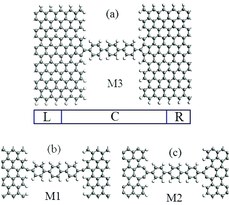
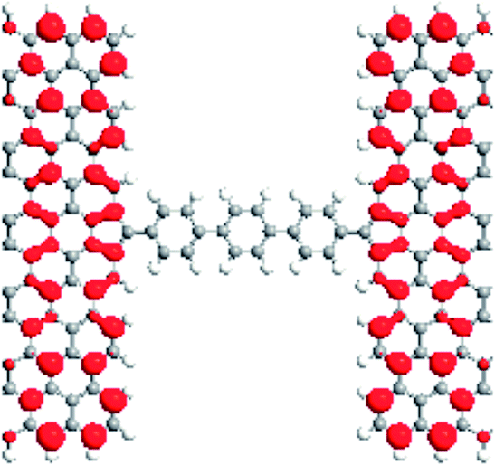
The ribbon widths of ZGNRs can be characterized by the number of zigzag C chains, N, along the nanoribbon axis, and is denoted as NZGNRs. An even and odd N correspond to symmetric and asymmetric ZGNRs. Here, we chose 11 and 12ZGNRs as the two types of electrodes. The structure of the molecular device is illustrated schematically in Fig. 1, which is divided into three regions, left (right) electrode and the scattering region. For M1 (M2, M3), the connecting configurations between the terphenyl molecule and the ZGNRs electrodes are dangling (pentagon, heptagon).
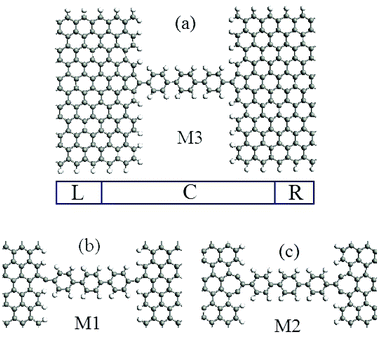 |
| | Fig. 1 (a) The geometric structures of model M3, (b) and (c) correspond to the different connection interfaces between the electrodes and the central molecule for models M1 and M2. L (R) and C indicate the left (right) electrodes, and the central scattering region, respectively. | |
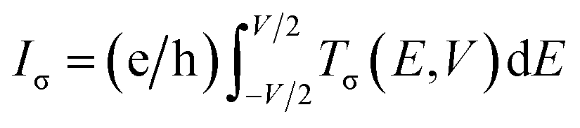
The geometry optimizations and the calculation of the electronic properties were performed using a first-principles method based on density functional theory (DFT) combined with the non-equilibrium Green's function (NEGF) technique, as implemented in the Atomistix ToolKit software. The spin generalized gradient approximation (SGGA) was used as the exchange–correlation functional. The real space grid techniques were used with an energy cutoff of 200 Ry as the required cutoff energy in numerical integrations and as the solution to the Poisson equation using a fast Fourier transform (FFT). The geometrical structures used were optimized until all residual forces on each atom were smaller than 0.01 eV Å−1 under the periodic boundary condition. The wave function was expanded by a double-zeta plus polarization (DZP) for all atoms. The current, I, in the systems, as a function of the applied external bias, V, can be calculated from the Landauer-like formula:25  , in which σ = α and β spin. The region of the bias window is [−eV/2, +eV/2], and Tσ(E,V) is the bias-dependent transmission coefficient.
3. Results and discussion
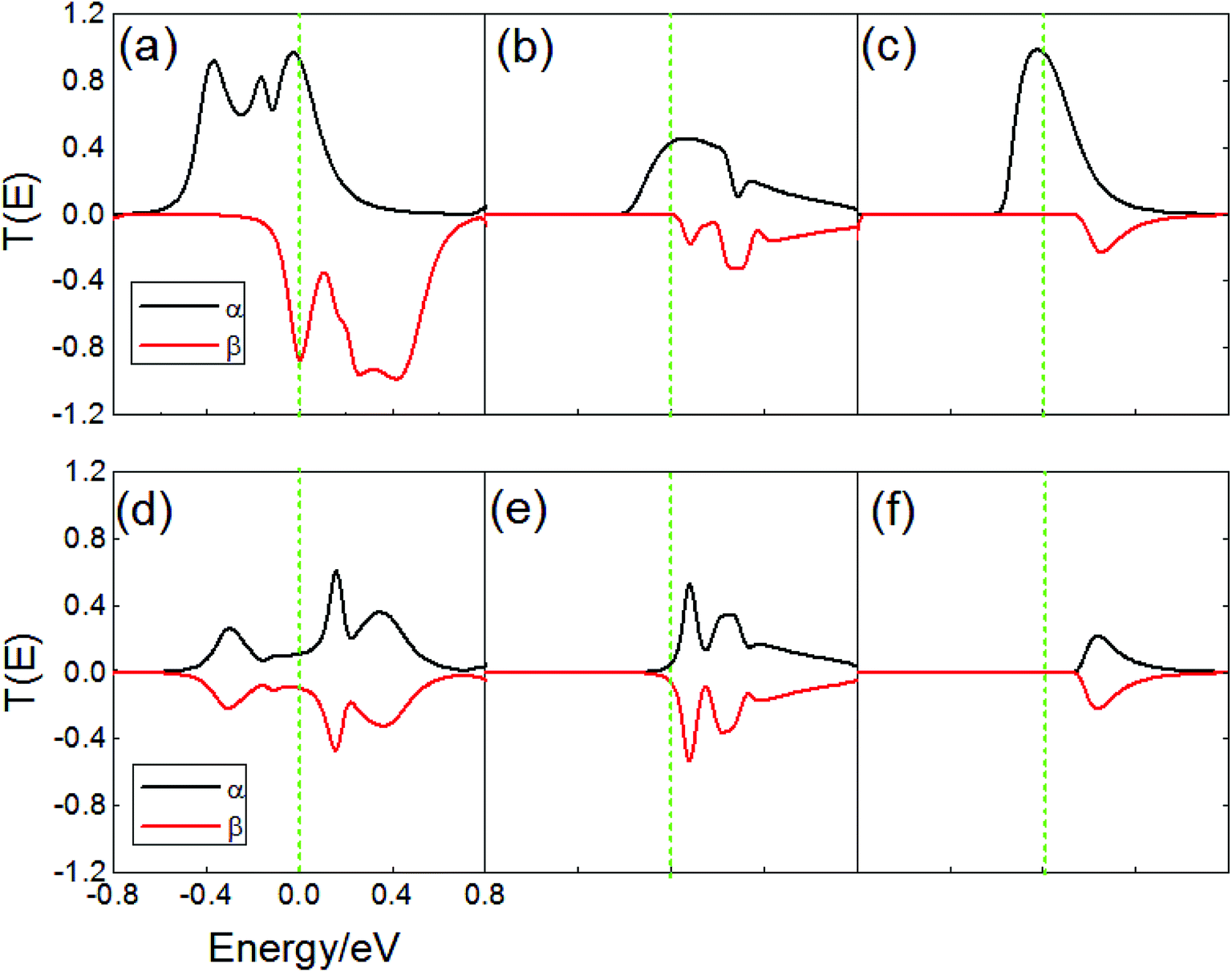
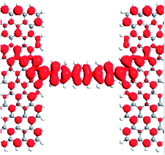
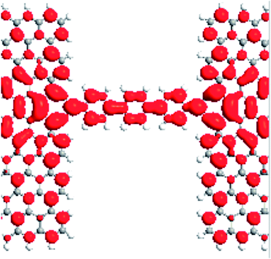
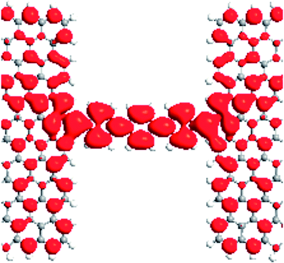
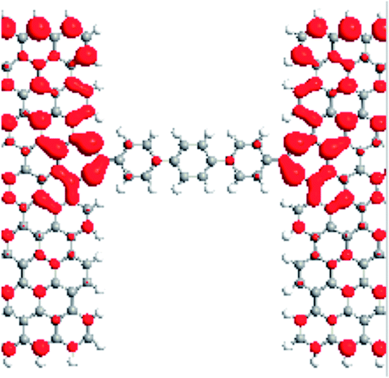
When the external magnetic fields applied to two electrodes are the same or in the opposite direction, magnetic ordering is denoted as parallel (P) [1, 1] or antiparallel (AP) [1, −1].14 Fig. 2a–f demonstrates the spin density for M1–M3 with the isosurface of the spin density (∇ρ = ρα − ρβ) in the P and AP magnetic configurations, in which ρα and ρβ denote the electron density of the α-spin (magenta) and β-spin (cyan), respectively. As can be seen, the localized magnetic distribution at the interface is obviously different, which is a reduction at the interface from M1 to M2 (M3). Meanwhile, the magnetic distribution for the two spin component in the molecules are completely different in each of the three models, and change with the external magnetic configurations. Using M3 as an example, there exists a net α-spin magnetic moment at the molecule and the interface with M3 in the P configuration, while both the α- and β-spin magnetic moment are distributed asymmetrically on the molecule in the AP configuration, as shown in Fig. 2c and f, respectively, which give rise to a spin splitting and degeneration in the central region. Fig. 3 shows the transmission spectra for M1–M3 at zero bias in the P and AP configurations, which show completely different behaviors at equilibrium. It is notable that the transmissions are different: for M1, the transmission coefficients are finite at the Fermi level for two spins, and the value in the P configuration is larger than the AP configurations (Fig. 3a and d). While the β-spin transmission coefficients are almost equal to zero at the Fermi level for M2 (M3) in the P configuration, and pronounced α-spin transmission peaks can be observed in the Fermi level region, which contributes to the α-spin current. Therefore, the spin-filter efficiency (SFE) is η = |(Tα − Tβ)/(Tα + Tβ),26 and 100% spin polarization can be obtained. For M3, the energy position of the β-spin transmission peak is far away from the Fermi level when compared with M2, we can predict that M3 will show a larger bias region with a spin filtering effect. For the AP state, the three models show spin-degenerate behaviors, which originate from the mismatch of the scattering states between the two electrodes with opposite spin directions.
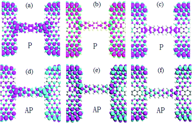 |
| | Fig. 2 The spin density isosurfaces for M1–M3 in the P and AP configurations: (a) M1 in P configuration; (b) M2 in P configuration; (c) M3 in P configuration; (d) M1 in AP configuration; (e) M2 in AP configuration; and (f) M3 in AP configuration. | |
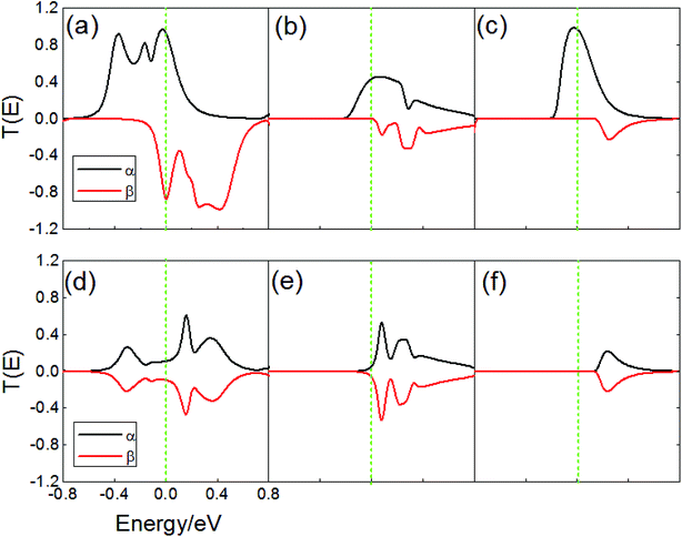 |
| | Fig. 3 (a)–(c) Transmission spectra for M1–M3 in the P and (d)–(f) AP configurations. The Fermi level is set to zero, as indicated by the green vertical dotted lines. | |
To provide an insight into the transmission behavior discussed above, we investigated the local density of states (LDOS) at the Fermi level in the P configuration, which can describe the space-resolved density of states (DOS).27,28 The LDOS can tell us the contributions of every atom to the device DOS, and can be used to gain insights into a solid-state device. From Table 1, it is evident that the LDOS of the α- and β-spin for M1 are delocalized on the terphenyl molecules, interfaces and two electrodes. There are large overlaps between the extended π-orbitals of the dangling carbon atoms and the delocalized big π-orbital which origin from the terphenyl ring and electrodes. This is to say, α- and β-spin scattering states are well extended on the whole on the devices. Thus, the two kinds of spin electrons can easily transport from one electrode to the other one. For M2 (M3), the LDOS of α-spin are completely delocalized on the whole device, and extended orbitals are formed between the pentagon (heptagon) and terphenyl molecule, and the electrons can easily go through the devices. The LDOS of β-spin for M2 and M3, however, are localized mainly on the electrodes, and rarely on the terphenyl molecules. As a result, the β-spin transmission coefficients near the Fermi level are about zero.
Table 1 The α and β LDOS spin density for M1–M3 in the P configuration
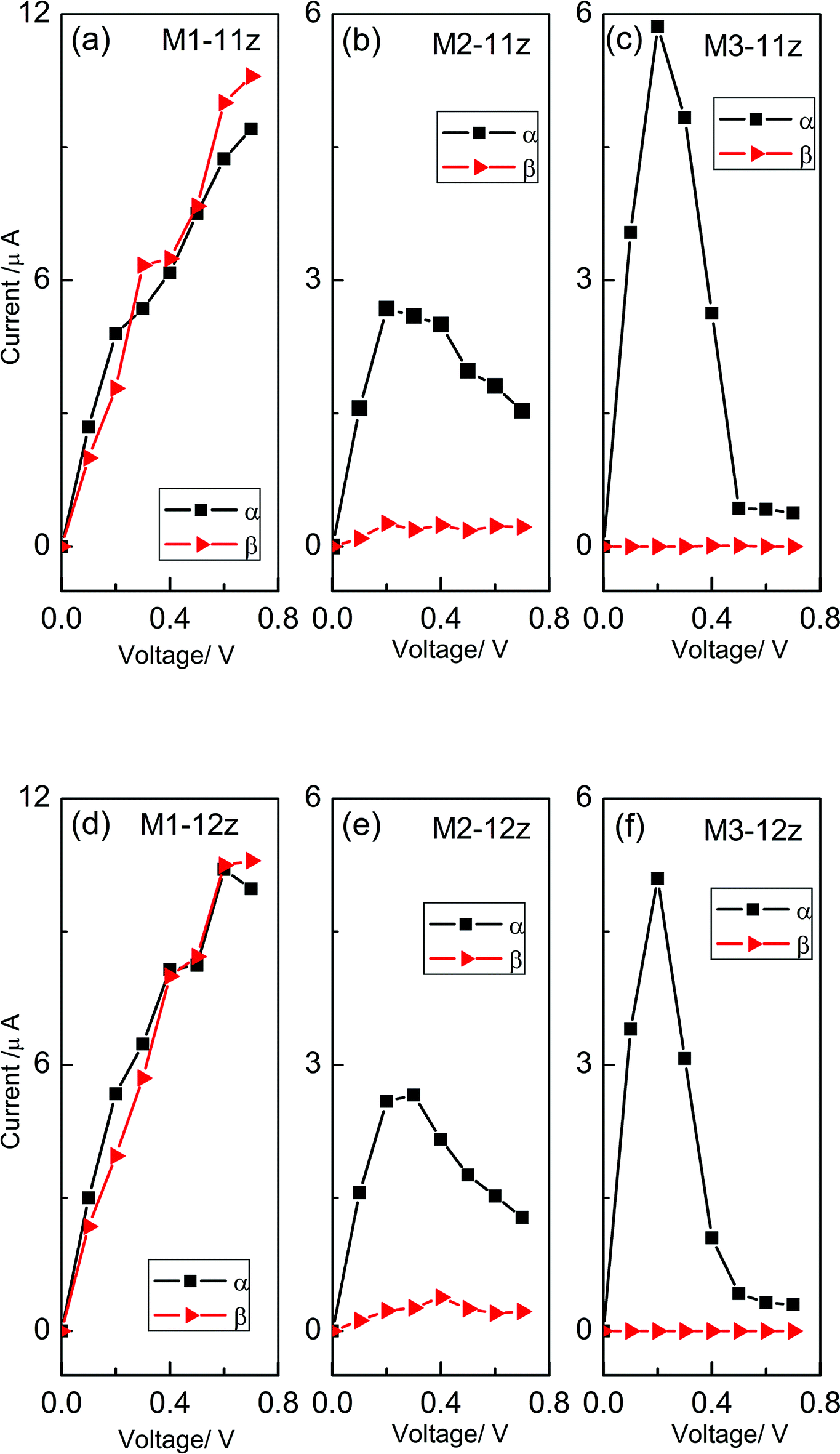
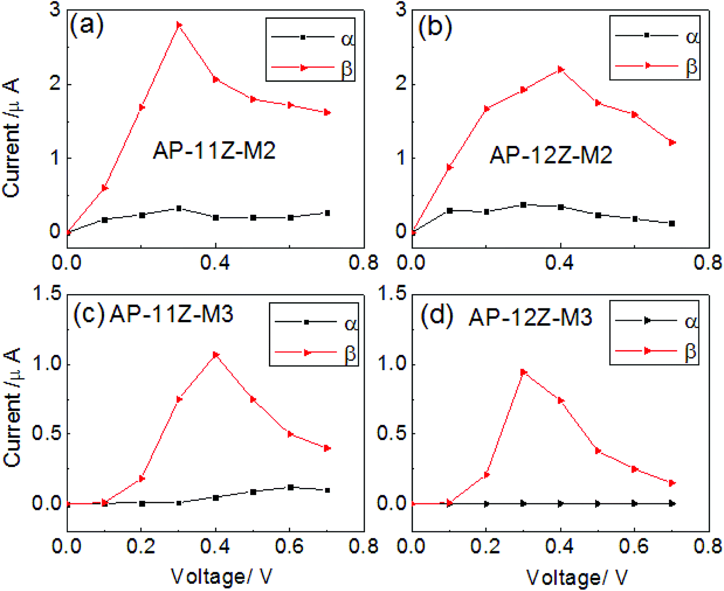
Fig. 4 displays the spin-resolved I–V characteristics for M1–M3 with ZGNR widths of 11 and 12 in the P configuration. For convenience, we marked them as M1(2,3)-NZ, then in the AP configurations, we marked them as AP-M1(2,3)-NZ, N = 11 and 12. As can be seen, they are obviously different. This indicates that the magnetic transport feature strongly depends on the combined manner and is independent of the ZGNR widths. For M1, both the α- and β-spin currents rise almost monotonously when the bias is increased, as shown in Fig. 4a and d. While for M2, Iα increases linearly when the bias voltage increases from zero to about 0.3 V and then decrease gradually, which is a negative differential resistance (NDR), and Iβ shows the familiar law, but its value is much less than Iα for the entire bias voltages, as shown in Fig. 4b and e. For M3, Iα also shows NDR behavior and reaches a maximum value at 0.2 V, but Iβ is always negligibly small in the calculated bias region, almost entirely suppressed, as shown in Fig. 4c and f. Therefore, the pentagon system permits α-spin electrons transmission but scatters β-spin electrons completely. However, a perfect ZGNR device does not show any spin polarization under the P configuration.14,29 Therefore, a remarkable rise in the spin polarization for M2 and M3, and an interface-induced special spin polarization can be obtained.30,31 Here, we define the SFE as η = |(Iα − Iβ)/(Iα + Iβ). The calculated results for the magnetic device effects are plotted in Fig. 5. Obviously, in the P configuration, M3 exhibits a spin filtering effect with a high SFE approaching almost 100% in a very large bias region from 0 to 0.7 V. The SFE of M2 is from 85% to 95% in the whole bias region. On the other hand, the SFE of M1 can be neglected. This suggests that the pentagon structure is favorable for spin filtering of the electron. In the AP configuration, the case is different, as shown in Fig. 6. As an example, M3 has a large Iβ except at 0.1 V, and a negligible small Iα at the bias, which shows the higher spin filtering effect. Due to the existence of the threshold voltage at 0.1 V, the currents in the AP configuration are lower than in the P configuration. M2 also shows this spin polarization feature, but the SFE is still lower than M3. In other words, the perfect spin filtering effect can be obtained in the P and AP configurations.
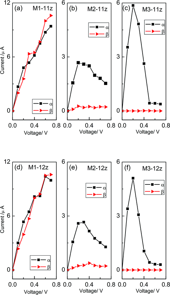 |
| | Fig. 4 (a)–(c) The I–V curves for M1–M3 with a ZGNR width of 11 in the P configuration, and (d)–(f) the I–V curves for M1–M3 with a ZGNR width of 12 in the P configuration. | |
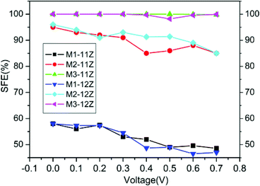 |
| | Fig. 5 The SFE curves for M1–M3 with different ZGNR widths of 11 and 12 in the P configuration. | |
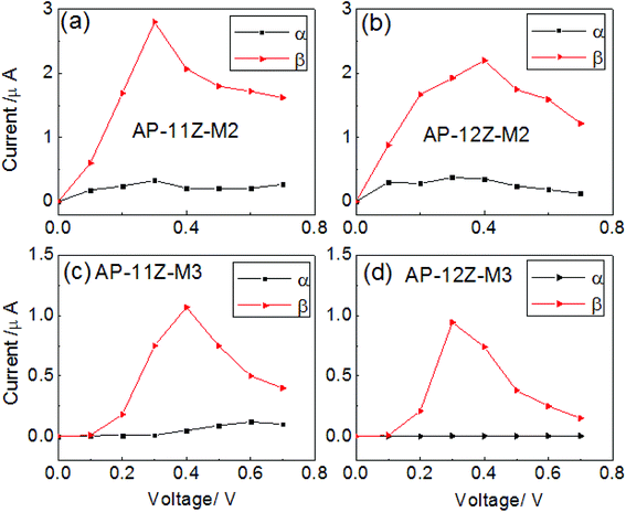 |
| | Fig. 6 The I–V curves for M2 and M3 with different ZGNR widths 11 and 12 in the AP configuration: (a) M2 11; (b) M3 11; (c) M2 12; and (d) M3 12. | |
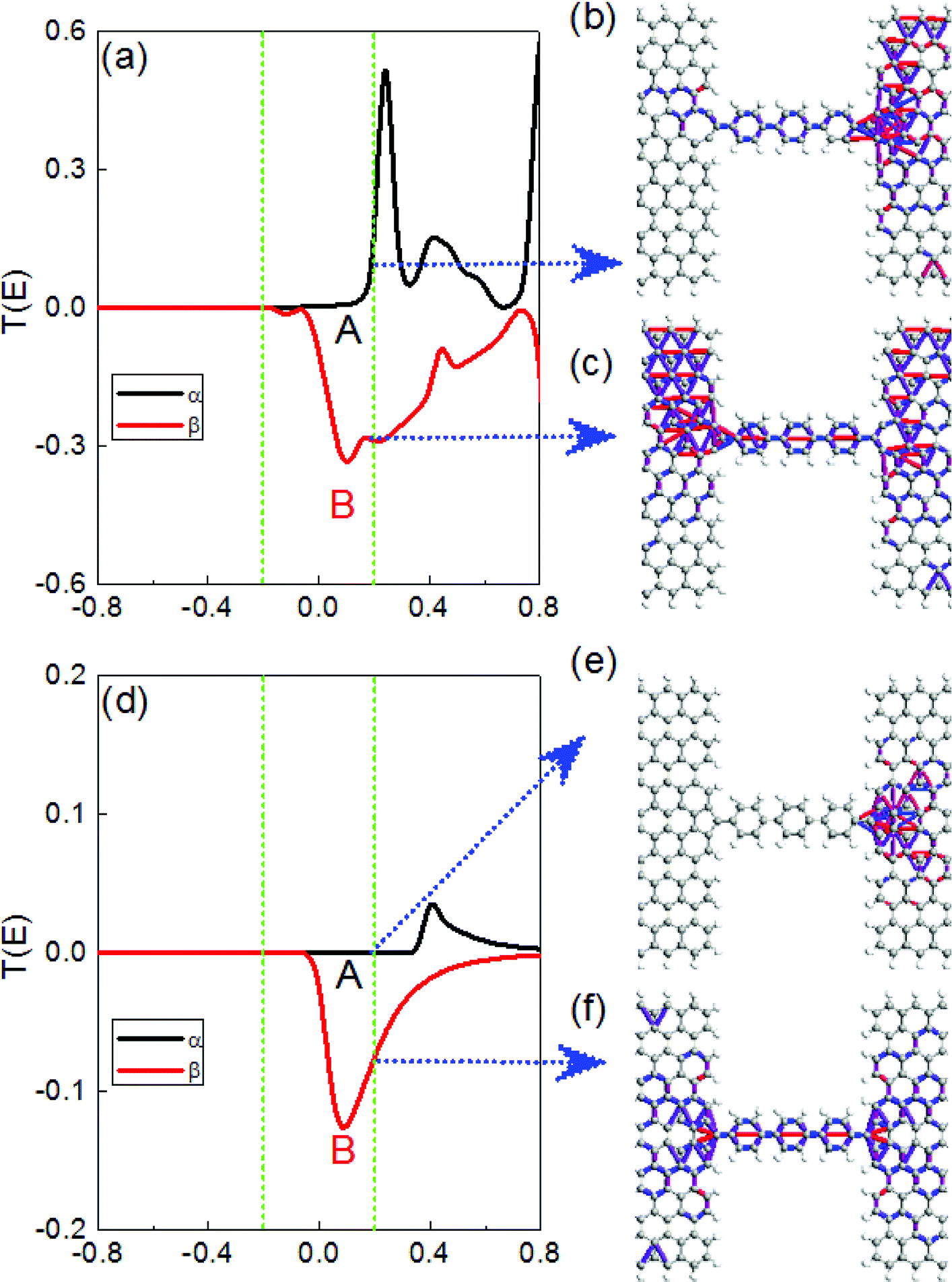
To give a better explanation of the spin filtering effect, the spin-dependent transmission spectra for M2 and M3 at 0.4 V bias were plotted and are shown in Fig. 7a and d. The transmission spectrum of the two spin channels are obviously different. High β-spin transmission peaks for the two models are observed within the bias windows, which are [−0.2, 0.2] eV. In contrast, the α-spin transmission coefficients remain at zero in the bias windows for M3, while there is a tail existence of the high α-spin peak near the 0.2 eV energy for M2. Therefore, the β-spin current is much larger than the α-spin, leading to a spin filtering effect, and M3 shows a higher perfect SFE than M2. Next, we investigated the electron transmission pathway, which can show where (and how) the current propagates.32–34
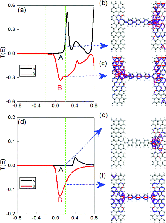 |
| | Fig. 7 (a) and (d) transmission spectra for M2 and M3 with a ZGNR width of 12 in the AP configuration at a 0.4 V bias, (b) and (e) correspond to α-spin transmission pathways, (c) and (f) correspond to β-spin transmission pathways, the energy point is 0.2 eV, the region between the two green dashed lines indicates the bias window, and the Fermi level is set to zero. | |
The α- and β-spin transmission pathway at 0.2 eV for M2 (M3) are shown in Fig. 7b, c, e, and f. Two different current channels exist, one via a chemical bond and one obtained through hopping between atoms. It is notable that the α- and β-spin electron for M2 can flow through the central molecule mainly via a chemical bond and can reach the other electrode through two current channels, as well as the β electron of M3. However, the α electron cannot transmit on the device, and the corresponding transmission is weak for M3, as shown in Fig. 7e.
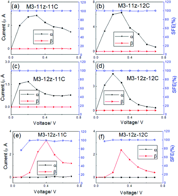
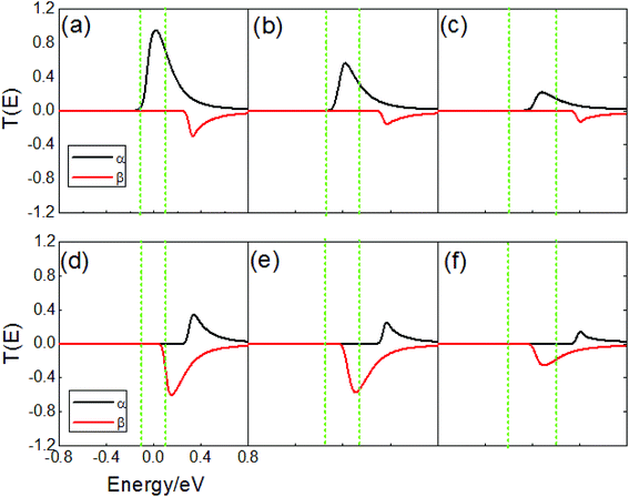
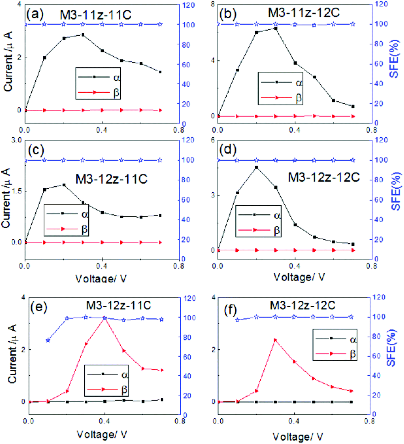
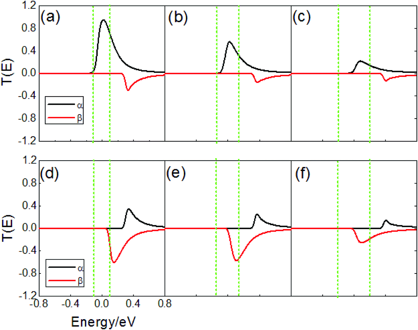
Next, the terphenyl molecules were replaced by the carbon chains based on M3. Here, the width of ZGNR is N = 11 and 12. The carbon chain with odd (even) carbon atoms shows a different bond type, we chose two kinds of carbon chain consisting of 11(12) carbon atoms. Considering the electrode and the length of the carbon chains, we designed four models, denoted as M3-11z-11(12)C and M3-12z-11(12)C. The spin current–voltage (V) characteristics of the four models are presented in Fig. 8a–d. One can see that the α-spin current increases obviously from the 0 to 0.2 V (0.3 V) bias, then decreases gradually, the currents for the models of the 12 carbon chain drop more quickly than those for the 11 carbon chain, and the NDR can be obtained for these models. However, the β-spin current is always negligibly small within the whole bias range. This suggests that the α-spin electrons can flow through the carbon chain freely, but that the β-spin electrons are scattered completely, which shows a perfect spin filtering behavior. In the AP configuration, using M3-12Z-11(12)C as an example, the α-spin currents are almost zero in the whole bias region, but the β-spin currents show a high value after 0.2 V, as shown in Fig. 8e and f. It is thus clear that a perfect spin filtering effect (around 100% SFE) can be realized in the AP configuration. In order to explain the spin I–V characteristics of devices for M3-12Z-12C, we created a comparison chart for the transmission spectra at various bias in Fig. 9. In the P configuration, a typical resonant tunneling of α-spin electrons in the vicinity of Fermi level are found, which weaken with increasing bias, leading to a decrease in the α-spin currents, and the β-spin transmission channel cannot enter into the bias windows, therefore, a perfect spin-filtering effect can be obtained. In the AP configuration, the α-spin transmission peak shifts to a high energy and always stays outside of the bias windows, and the current is determined by the β-spin tunneling integral within the bias window, which arrives at the maximum value at a bias of 0.4 V.
 |
| | Fig. 8 (a)–(d) The I–V and SFE curves for the carbon chain models with ZGNR widths of 11 and 12 in the P configuration, (e) and (f) are in the AP configuration with 12ZGNR, the connection interface is a pentagon. | |
 |
| | Fig. 9 (a)–(c) Transmission spectra of M3-12Z-12C at 0.2–0.4 V in the P magnetism configuration, and (d)–(f) in the AP magnetism configuration. | |
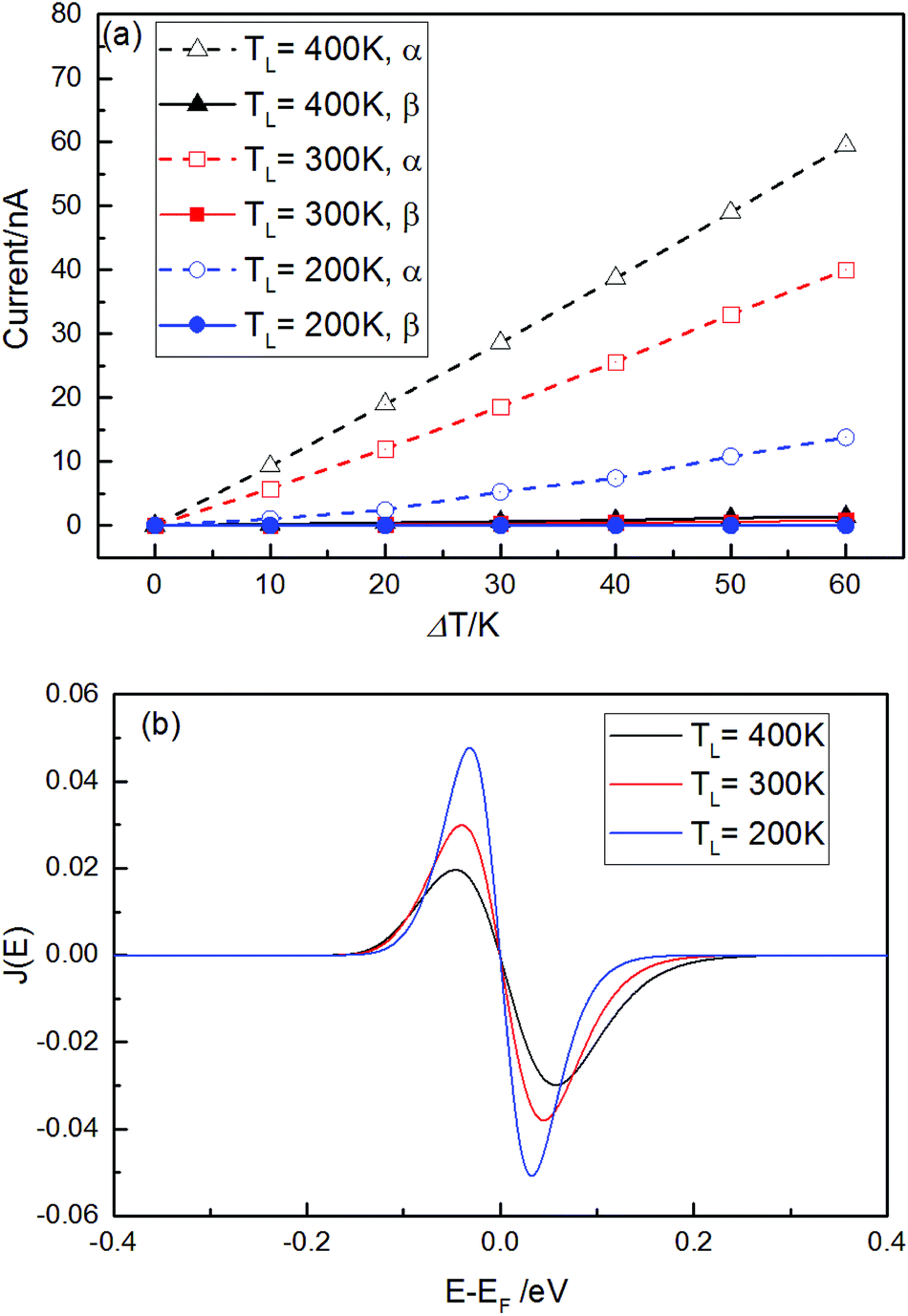
Finally, the spin-dependent thermoelectronic transport calculations were also investigated for M3-12Z-12C in the P magnetism configuration as an example of the pentagon-linkage system. The thermally-driven spin-dependent current through the device is calculated using the Landauer formula: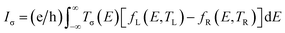 , in which σ is the index of the α- and β-spin, TL and TR represent the temperature of the left and right electrode. The difference in the carrier concentrations between the left and the right electrode is determined by the Fermi distribution (fL(E,TL) − fR(E,TR)), which is intimately related to the electron temperature at the two electrodes.35 Fig. 10a shows the spin-dependent currents versus the temperature difference (ΔT = TL − TR), in which TL = 200 (300, 400) K. As can be seen from the figure, the α-spin current can pass through the device, which increases linearly with the increase of ΔT, and the β-spin current is strongly suppressed. As Iα is always much larger than Iβ at the same ΔT and TL, a perfect thermal spin-filtering effect can be obtained, and the polarization of the spin current is close to 100%. The thermally-driven spin currents through the device are the joint outcomes of the transmission spectra and the difference in the Fermi–Dirac distributions. Owing to the exponential decaying nature of the Fermi distribution, the thermally-driven currents only depend on the transmission near the Fermi energy. The α-spin current spectra J(E) = T(E)[fL(E,TL) − fR(E,TR)]35 is plotted in Fig. 10b, in which the cover area under the curves determines the thermally-driven current and ΔT = 60 K with different TL = 200, 300, and 400 K. The cover area of the α-spin J(E) above the Fermi level is larger than that below the Fermi level at fixed TL, resulting in the hole current Ih being larger than the electron current Ie. Therefore, a positive α-spin current can be obtained. For β-spin, J(E) almost disappears for different TL owing to there being no β-spin transmission close to the Fermi energy.
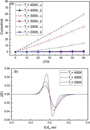 |
| | Fig. 10 (a) The spin dependent currents versus ΔT for different TL. (b) The α-spin current spectra for different TL (TL–R = 60 K). | |
4. Conclusions
Based on the NEGF method combined with DFT, we investigated the spin transport properties for terphenyl molecule bridging in ZGNR electrodes with different connecting configurations, which included dangling, heptagon, and pentagon-linkages. The results show that the transport properties are affected by the connecting configurations and spin configuration of the electrodes. For the pentagon-linkages system in the P configuration, a very high spin filtering effect (close to 100% spin polarization) can be obtained, followed by the heptagon-linkages system, and the spin filtering effect of the dangling-linkages system is almost negligible. In the AP configuration, however, it is interesting that the pentagon- and heptagon-linkages systems show an adverse spin filtering effect compared with the P configuration. We also investigated the spin transport properties of the carbon chains connected with ZGNR electrodes with pentagon-linkages in the P and AP configuration, and found that the spin filtering effects are intrinsic. Finally, we further investigated the spin-dependent thermoelectronic transport properties of the carbon chains model with pentagon-linkages system, and the results show that this system exhibits almost 100% thermal spin polarization. The obtained results will provide structural models, theoretical references, performance parameters, and new ideas for the delicate manufacture of functional magnetic devices.
Conflicts of interest
There are no conflicts to declare.
Acknowledgements
This work was supported by the National Natural Science Foundation of China (Grant No. 61771076, 61371065 and 51604042), the Aid Program for Science and Technology Innovative Research Team in Higher Educational Institutions of Hunan Province, and the Scientific Research Innovation Fund for Postgraduate of Changsha University of Science and Technology.
References
- X. K. Chen, J. Liu, Z. H. Peng, D. Du and K. Q. Chen, Appl. Phys. Lett., 2017, 110, 1121 Search PubMed.
- T. Low and F. Guinea, Nano Lett., 2010, 10, 3551 CrossRef CAS PubMed.
- J. M. Zheng, P. Guo, Z. Ren, Z. Jiang, J. Bai and Z. Zhang, Appl. Phys. Lett., 2012, 101, 666 Search PubMed.
- Q. X. Dong, R. Hu, Z. Q. Fan and Z. H. Zhang, Carbon, 2018, 130, 206–214 CrossRef CAS.
- X. Q. Deng, Z. H. Zhang, G. P. Tang, Z. Q. Fan, C. H. Yang and L. Sun, Carbon, 2014, 66, 646–653 CrossRef CAS.
- W. Han and R. K. Kawakami, Phys. Rev. Lett., 2011, 107, 047207 CrossRef PubMed.
- X. Q. Deng, Z. H. Zhang, G. P. Tang, Z. Q. Fan, C. H. Yang and L. Sun, Carbon, 2015, 94, 317–325 CrossRef CAS.
- R. R. Pandey, M. Fukumori, A. Termeh, M. Eguchi, D. Tanaka, T. Ogawa and H. Tanaka, Nanotechnology, 2017, 28, 175704 CrossRef PubMed.
- K. Janani and D. J. Thiruvadigal, Appl. Surf. Sci., 2018, 449, 829–837 CrossRef CAS.
- L. Miao, R. Jia, Y. Wang, C. P. Kong, J. wang, R. Eglitis and H. X. Zhang, J. Saudi Chem. Soc., 2017, 21, 111–117 CrossRef CAS.
- Y. An and Z. Yang, Appl. Phys. Lett., 2011, 99, 192102 CrossRef.
- H. S. Moon, J. M. Yun, K. H. Kim, S. S. Jang and S. G. Lee, RSC Adv., 2016, 6, 39587–39594 RSC.
- X. H. Zheng, L. L. Song, R. N. Wang, H. Hao, L. J. Guo and Z. Zeng, Appl. Phys. Lett., 2010, 97, 666 Search PubMed.
- W. Y. Kim and K. S. Kim, Nat. Nanotechnol., 2008, 3, 408 CrossRef CAS PubMed.
- S. S. Alexandre, A. D. Lúcio, A. H. Neto and R. W. Nunes, Nano Lett., 2012, 12, 5097 CrossRef CAS PubMed.
- E. Loginova, S. Nie, K. Thürmer, N. C. Bartelt and K. F. Mccarty, Phys. Rev. B: Condens. Matter Mater. Phys., 2009, 80, 1956 CrossRef.
- J. Lahiri, Y. Lin, P. Bozkurt, H. Oleynik and M. Batzill, Nat. Nanotechnol., 2010, 5, 326 CrossRef CAS PubMed.
- G. P. Tang, J. C. Zhou, Z. H. Zhang, X. Q. Deng and Z. Q. Fan, Carbon, 2013, 60, 94–101 CrossRef CAS.
- D. Wang, Z. H. Zhang, X. Q. Deng, Z. Q. Fan and G. P. Tang, Carbon, 2016, 98, 204–212 CrossRef CAS.
- M. Kiguchi, H. Nakamura, Y. Takahashi, T. Takahashi and T. Ohto, J. Phys. Chem. C, 2010, 114, 22254 CrossRef CAS.
- A. Saraivasouza, M. Smeu, H. Terrones, A. G. S. Filho and M. A. Ratner, J. Phys. Chem. C, 2015, 117, 21178–21185 CrossRef.
- C. M. Jaworski, R. C. Myers, E. Johnston-Halperin and J. P. Heremans, Nature, 2012, 487, 210 CrossRef CAS PubMed.
- K. R. Jeon, B. C. Min, A. Spiesser, H. Saito, S. C. Shin, S. Yuasa and R. Jansen, Nat. Mater., 2014, 13, 360 CrossRef CAS PubMed.
- S. G. Kwon, S. Back, J. E. Park and B. Kang, J. Mater. Chem. C, 2018, 6, 7759–7766 RSC.
- R. Landauer, Philos. Mag., 1970, 21(172), 863 CrossRef CAS.
- J. Zeng and K. Q. Chen, J. Mater. Chem. C, 2013, 1, 4014–4019 RSC.
- Y. Yamagishi, S. Nakashima, K. Oiso and K. Yamada, Nanotechnology, 2013, 24, 395704 CrossRef CAS PubMed.
- X. Q. Deng, Z. H. Zhang, L. Sun and L. J. Wu, Org. Electron., 2017, 41, 276–383 CrossRef.
- M. Zeng, L. Shen, M. Zhou, C. Zhang and Y. Feng, Phys. Rev. B: Condens. Matter Mater. Phys., 2011, 83, 115427 CrossRef.
- H. Q. Wan, B. H. Zhou, W. H. Liao and G. H. Zhou, J. Chem. Phys., 2013, 138, 034705 CrossRef PubMed.
- X. Zhou, Y. Liu, M. Zhou, H. Shao and G. Zhou, Appl. Phys. Express, 2014, 7, 021201 CrossRef.
- G. C. Solomon, C. Herrmann, T. Hansen, V. Mujica and M. A. Ratner, Nat. Chem., 2010, 2, 223 CrossRef CAS PubMed.
- D. Zhang, M. Long, X. Zhang and H. Xu, RSC Adv., 2015, 5, 96455 RSC.
- Z. Q. Fan, W. Y. Sun, Z. H. Zhang, X. Q. Deng, G. P. Tang and H. Q. Xie, Carbon, 2017, 122, 687–693 CrossRef CAS.
- M. Zeng, Y. Feng and G. Liang, Nano Lett., 2011, 11, 1369 CrossRef CAS PubMed.
|
| This journal is © The Royal Society of Chemistry 2018 |
Click here to see how this site uses Cookies. View our privacy policy here. 
 Open Access Article
 This Open Access Article is licensed under a Creative Commons Attribution-Non Commercial 3.0 Unported Licence
 * and
R. Q. Sheng
* and
R. Q. Sheng
 , in which σ = α and β spin. The region of the bias window is [−eV/2, +eV/2], and Tσ(E,V) is the bias-dependent transmission coefficient.


 , in which σ is the index of the α- and β-spin, TL and TR represent the temperature of the left and right electrode. The difference in the carrier concentrations between the left and the right electrode is determined by the Fermi distribution (fL(E,TL) − fR(E,TR)), which is intimately related to the electron temperature at the two electrodes.35 Fig. 10a shows the spin-dependent currents versus the temperature difference (ΔT = TL − TR), in which TL = 200 (300, 400) K. As can be seen from the figure, the α-spin current can pass through the device, which increases linearly with the increase of ΔT, and the β-spin current is strongly suppressed. As Iα is always much larger than Iβ at the same ΔT and TL, a perfect thermal spin-filtering effect can be obtained, and the polarization of the spin current is close to 100%. The thermally-driven spin currents through the device are the joint outcomes of the transmission spectra and the difference in the Fermi–Dirac distributions. Owing to the exponential decaying nature of the Fermi distribution, the thermally-driven currents only depend on the transmission near the Fermi energy. The α-spin current spectra J(E) = T(E)[fL(E,TL) − fR(E,TR)]35 is plotted in Fig. 10b, in which the cover area under the curves determines the thermally-driven current and ΔT = 60 K with different TL = 200, 300, and 400 K. The cover area of the α-spin J(E) above the Fermi level is larger than that below the Fermi level at fixed TL, resulting in the hole current Ih being larger than the electron current Ie. Therefore, a positive α-spin current can be obtained. For β-spin, J(E) almost disappears for different TL owing to there being no β-spin transmission close to the Fermi energy.