
 Open Access Article
 This Open Access Article is licensed under a Creative Commons Attribution-Non Commercial 3.0 Unported Licence
Ethylenediamine mediated luminescence enhancement of pollutant derivatized carbon quantum dots for intracellular trinitrotoluene detection: soot to shine†
S. Devia,
Raju K. Gupta b,
A. K. Paulc,
Vinay Kumard,
Abhay Sachdeva,
P. Gopinathd and
S. Tyagi*a
b,
A. K. Paulc,
Vinay Kumard,
Abhay Sachdeva,
P. Gopinathd and
S. Tyagi*a
aAnalytical Techniques Division, CSIR-CSIO, Chandigarh 160030, India. E-mail: matsachin@gmail.com; sachintyagi@csio.res.in; Fax: + 91-172-2657267; Tel: +91-172-2642545 (O)
bIndian Institute of Technology, Kanpur, Uttar Pradesh, India
cDeshBhagat University, Fatehgarh Sahib, Punjab, India
dIndian Institute of Technology Roorkee, Roorkee, Uttarakhand, India
First published on 21st September 2018
Abstract
Vehicle-generated toxic pollutants are composed of gaseous smoke and particulate byproducts accumulated as a black substance at its exhaust. This particulate matter (soot) is utilized for the green synthesis of highly stable, non-toxic, environment friendly, carbon quantum dots (CQD). The CQDs are synthesized via the simple hydrothermal route in the absence (C1) and presence (C2) of oxidants. The as-synthesized CQDs are amine functionalized using ethylenediamine. The amine functionalized CQDs (C1N and C2N) are explored for trinitrotoluene detection. From transmission electron microscopy, the average size of C1 and C2 was found to be about 4.2 nm and 5.6 nm respectively. The incorporation of amine groups lead to an increase in quantum yields from 5.63% to 12.7% for C1 and from 3.25% to 8.48% for C2 QDs. A limit of detection (LOD) of 13 ppb was displayed by C1N while the LODs of 11 ppb and 4.97 ppb were delivered by C2N at λex 370 nm and λex 420 nm respectively. The Stern–Volmer constant for C1N is 2.02 × 10⁶ M−1 while for C2N at λex 370 nm and λex 420 nm is 0.38 × 10⁶ M−1 and 0.48 × 10⁶ M−1 respectively. Furthermore, C1N presents high selectivity for TNT compared to C2N. Owing to their higher luminescence, C1N particles are successfully demonstrated for their applicability in intracellular TNT detection.
1. Introduction
Transportation is a major source of pollution in the world due to a large number of available vehicles. Vehicle-generated pollutants, such as carbon monoxide, hydrogen, nitrogen oxide, vehicle soot or particulate matter, ammonia and sulfur dioxide, impose many adverse effects on living such as health and the environment.1 The release of burnt fuel byproducts and soot into the atmosphere is the main cause for transportation mediated environment pollution. A black substance can be noticed looking at the exhaust of a car. With time, a lot of this accumulates and the soot is spread in the air and on the ground as the car moves, which is very harmful to people's health as well as the environment.1 The situation is much worse when the matter is fine because it can easily be spread by moving air. This results in global warming, poor air quality, lack of international reputation, various health issues, decreased tourism, smog, and acidic rain. The gaseous products are difficult to handle directly while the vehicle soot can be hindered for their direct entrance in the environment by reusing the soot. Carbon quantum dots (CQDs) have come into view as a recently developed and very potential fluorescent nanomaterial due to its outstanding optical properties, fantastic biocompatibility and accessible surface functional groups.2 CQDs deliver large application potential in a variety of areas. CQDs, can further be explored for various applications in different fields especially in chemosensing3 and biosensing applications,4 including photocatalysis,5 photovoltaic devices,6 optoelectronics,7 bioimaging,8,9 biolabeling,10 drug delivery,11 metal ion and explosive sensing12 etc.Presently, the researchers prefer the application of various natural bio-precursors over chemical modification and template-based synthesis for fabrication of carbon nanostructures via greener route. Several natural biomass precursors such as soy milk,13 sugarcane juice,14 coffee,15 egg yolk,16 and dextrin,17 and so on, have been reported for the CQDs synthesis. The resultant CQDs exhibited a high PL quantum yield (QY) and good water-solubility. Here, we report the synthesis of environment friendly, non-toxic and luminescent carbon quantum dots (CQDs) using the bike soot pollutant. This can be a possible approach in utilization of pollutant to the productive material, CQDs.
Nitroaromatic compounds cover a large fraction of hazardous explosive materials and prove to be very life-threatening upon long exposure. Trinitrotoluene (TNT) is one of the heavily used nitroaromatic explosives in various fields like mining, terrorist activities, military and defense area etc. which compels for its highly sensitive and selective detection. Different types of nanomaterials like dye-loaded porous nanomaterials,18 gold nanoparticles,19 and heavy metal QDs20 have been explored for the optical detection of TNT. But their shortcomings like less stability, cell toxicity, scarce functionality, high size polydispersity and decreased hydrophilicity limits their application.
While, CQDs deliver plenty of alluring properties like intense fluorescence, high quantum yield (QY), large functionality, non-toxic nature, hydrophilicity, excellent biocompatibility, high photostability and tunable photoluminescence (PL) which can present their potential candidature for TNT detection and other advanced potential applications.
Previous reports on p-nitrophenol (NP), a nitroaromatic compound, explored different CQDs based probes like β-cyclodextrin functionalized CQDs21 and phenylboronic acid functionalized CQDs (PBA-CQD)22 to detect NP forming non-fluorescent conjugates. Similar phenomenon of fluorescence quenching can be utilized for TNT detection by changing the functionalization ligand to amines on CQDs surface. Because for the phenolic nitroaromatic compounds like trinitrophenol (TNP) and NP, a different complex other than meisenheimer complex is formed with amine group which is yellow in colour. As shown by Wanko et al. for nitrophenolates, this complex is the result of the acid–base reaction between the amine group and the phenolic group to form phenolates.23,24 Therefore, amine ligand can deliver higher selectivity over different nitroaromatic TNT analogue compounds. So, amine capped CQDs can also be approached to selectively detect trinitrotoluene.
Therefore, in present research work carbon quantum dots were synthesized by using vehicle pollutant soot as precursor. The mechanism for the formation of carbon dots involves the carbonization of its constituents such as carbon black, organic aerosol and organic carbon etc. Further, synthesis route was optimized for the effect of absence (C1) and presence of oxidant nitric acid (C2). C1 and C2 were successfully amine functionalized with ethylenediamine (EDA) and explored for sensing of TNT. As lung cells are highly prone to explosive blast damage due to hemorrhage which is the primary blast effect on lungs that occurs due to overpressure and overpressure duration.25 So, clinging to this fact, TNT is also detected in liver cells (normal epithelial lung cell line, L-132) to advance the usability of this nanoprobe for intracellular TNT detection.
The “Turn Off” principle behind the TNT detection using these amine capped CQDs, C1N (derived from C1) and C2N (derived from C2) is shown in Fig. 1.
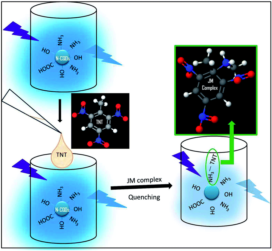 | ||
| Fig. 1 Schematic illustration of the principle for TNT detection using N-CQDs. | ||
2. Experimental
2.1 Materials and methods
The pollutant soot was collected form Hero Splendor plus 2009 bike's exhaust pipe and used as precursor for CQDs synthesis. Quinine sulfate (QS, 99.5%, AR) was supplied by CDH, India. 2,4,6-trinitrotoluene (TNT), dinitrotoluene (DNT) and 2,4-dinitrotoluic acid (TA) were purchased from Sigma Chemical Co. (USA). HNO3 and sulphuric acid (H2SO4) were supplied by Merck. Dialysis membrane-70 was bought from himedia. Disodium ethylenediaminetetraacetate dehydrate (Na2EDTA), Sodium bicarbonate (NaHCO3), nitrobenzene (NB) was purchased from Sigma-Aldrich. Deionized water (18 mΩ) was used throughout the study. All the chemicals were of analytical grade and used without further purification.2.2 Synthesis of CQDs (C1 and C2)
The hydrothermal synthesis of CQDs involves: (i) collection, grinding and sieving of bike soot (ii) carbonization of soot powder in respective solvents and (iii) purification of the product. The bike soot was collected in a glass Petri dish and grinded with pestle mortar to break the clumps. After sieving, the 0.02 g fine soot powder was mixed in 10 mL of DI water for the synthesis of C1. This solution was subjected to heat treatment in a 25 mL Teflon-lined autoclave at 140° for 10 h. 40 mL DI water was added into the dark brown colored product and centrifuged at 10![[thin space (1/6-em)]](https://www.rsc.org/images/entities/char_2009.gif) 000 rpm for 15 min. 10 mL C1 solution was dialyzed in 8 cm long activated dialysis membrane for 24 h against DI water. The deionized water was added in dialysate up to the final volume of 40 mL for further use.
000 rpm for 15 min. 10 mL C1 solution was dialyzed in 8 cm long activated dialysis membrane for 24 h against DI water. The deionized water was added in dialysate up to the final volume of 40 mL for further use.
C2 was synthesized using same procedure except the soot powder was mixed in 20 mL HNO3 (6.4 M) solution and heat treated at 180° for 8 h in Teflon-lined autoclave. The oxidative acid presence might affect the procedure in three expected manners: firstly, the breaking down the aggregates into nano-sized carbon particles, secondly, for solubilization of carbon nanoparticles, and thirdly, influence the emission characteristics. The driving force for the synthesis of spherical CQDs from soot material can be discussed as the strong oxidizing acids used in synthesis of CQD, amplify the carbonization of small organic molecules of soot to carbonaceous materials. The oxidative acid presence might affect the procedure in three expected manners: firstly, the breaking down the aggregates into nano-sized spherical carbon particles, secondly, for solubilisation of carbon nanoparticles, and thirdly, influence the emission characteristics.26 Moreover, aggregation of CQD was avoided by controlled pyrolysis in Teflon lined autoclave during hydrothermal synthesis.27
2.3 Amine capping of CQDs (C1N and C2N)
C1 and C2 were capped with EDA to subject the amine group on their surfaces. The EDA concentration required for complete surface capping was optimized. 2 mL each of the C1 and C2 solutions were taken as reference. The EDA was added in C1 solution having the C1:EDA (v/v) ratio of 1:0.005, 1:0.01, 1:0.025, 1:0.05, 1:0.1, 1:0.2, 1:0.3, 1:0.4, 1:0.5 and 1:1 (0.075 μM to 15 μM). Similarly, the EDA was added in C2 solution having the C2:EDA (v/v) ratio of 1:0.005, 1:0.01, 1:0.025, 1:0.25, 1:0.5 and 1:1 (0.075 μM to 15 μM). These solutions were checked for their PL emission intensity. The as-synthesized CQDs (C1, C2) and amine-capped CQDs (C1N, C2N) were characterized and compared using various analytical techniques. The schematic illustration of the synthesis and capping of C1 and C2 is shown in Fig. 2. The effects of dialysis and amine functionalization on the emission intensities of C1 and C2 are shown in Fig. S1† exhibiting the enhancement in their blue-colored emissions under the UV-illumination (365 nm).
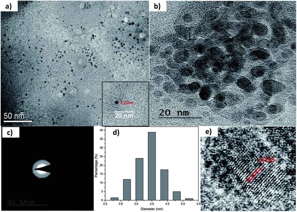 | ||
| Fig. 2 (a) and (b) TEM micrographs of as-synthesized C1 at different scales; (c) SAED pattern; (d) size distribution; and (e) lattice fringe analysis of as-synthesized C1. | ||
Here, the amine-terminated compound (EDA) acts as surface passivating agent for CQDs. The surface passivation is required for the enhanced photoluminescence (PL) of the CQDs.27
2.4 Quantum yield (QY) calculations
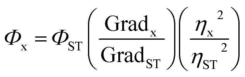
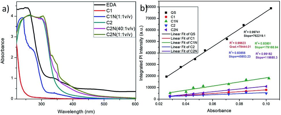
The standard dye used to measure the QY of the synthesized CQDs was quinine sulfate (QS) dissolved in 0.1 M H2SO4. The known QY of QS is 0.54 at λex 330 nm. The UV-vis absorption and PL emission spectra of QDs (C1, C2, C1N and C2N) and reference QS were measured separately. The QY values were calculated according to the equation as follow:In here ‘x’, ‘ST’, ‘Φ’ and ‘Grad’ stand for sample, standard, fluorescence quantum yield and the gradient from the plot of integrated emission intensity vs. absorbance respectively. The η represents the refractive index of solvents which is 1.33 for both the solvents 0.1 M H2SO4 and water.
2.5 TNT sensing study
Standard stock solutions (104 ppm) of TNT and various other nitroaromatic analogues compounds were prepared in acetonitrile. The TNT sensing study was performed using PL spectroscopy at different TNT concentrations as prepared from stock solution (220 μM to 44 nM in C1N solution and 0.308 μM to 44 nM in C2N solution). 3 mL of C1N and C2N solutions were used respectively for TNT detection (n = 3). For selectivity study, various other analogue nitroaromatic compounds (NB, DNT and 2-TA) were also studied using the PL spectroscopy.2.6 Analysis of real samples
The tap water was vacuum filtered using a 0.22 μm membrane for the removal of suspended particles. Then the samples were prepared by adding the known concentrations of TNT stock solution in filtered tap water. These TNT-spiked water samples were added in C1N and C2N solutions in 1:29 v/v ratio to make a final TNT concentration of 0.1, 1 and 10 ppm. Finally, these samples were characterized for their PL emission properties. The fluorescence intensity of the samples was found having good recoveries.
2.7 Cell culture
The normal epithelial lung cell line, L-132, was obtained from National Centre for Cell Sciences (NCCS) Pune, India. These cells were cultured in Dulbecco's modified Eagle's medium (DMEM, Himedia) complemented with 10% v/v fetal bovine serum (FBS, Gibco Life Technologies) and 1% penicillin–streptomycin solution (Sigma-Aldrich, USA). Cells were maintained in a humidified incubator (5% CO2/95% air atmosphere) at 37 °C.2.8 MTT assay
The cell viability of L-132 cells C1N at different concentrations (2, 4, 6, 8, 10 and 20 μg mL−1) was performed by MTT (3-(4,5-dimethylthiazol-2-yl)-2,5-diphenyltetrazolium bromide) assay on normal lung epithelial cell lines L-132. About 5000 cells were seeded on 96 well-plates and were then incubated at 37 °C and 5% CO2 for 12 hours. After 12 hours incubation, the different concentrations of C1N were added in each well and the cells were incubated at 37 °C and 5% CO2 for 48 hours. All the samples were evaluated in triplicates to avoid any inconsistency in result interpretation. After the completion of incubation period, the spent media was removed and 100 μL fresh media supplemented with 10 μL MTT reagent (5 mg mL−1) was added to each well. The treated cells were again transferred to the incubator for another 4 hours at 37 °C and 5% CO2. At the end of the incubation period, the spent media was aspirated from each well and the formazan crystals formed by the cells was dissolved by adding 100 μL DMSO to each well. Further the concentration of formazan crystals formed in each well was estimated by recording absorbance at 570 nm and background absorbance at 690 nm for the respective well in multimode plate reader (Biotek Cytation 3). The acquired absorbance values are converted to percentage of viable cells using the formula:
2.9 Intracellular bioimaging in presence of TNT
For imaging experiments, L-132 cells were pre-treated with TNT (4 ppm) for 12 h. These TNT treated cells were further incubated with 20 μg mL−1 of C1N for another 4 h, as the cells were observed having good viability at this concentration. Subsequently, the cells were washed with sterile phosphate buffer saline (PBS) in order to remove excess salt. Images were then captured using DAPI and GFP filters of fluorescence microscope (EVOS FL Colour, AMEFC 4300) for capturing the blue and green emission of CQDs.3. Results & discussion
3.1 Characterization of as-synthesized C1 and C2
The morphological characterization of C1 and C2 was performed using TEM. In Fig. 2a and b, it can be observed that as-synthesized C1 are having spherical shape, monodisperse nature and an average diameter of 4.2 nm. The size distribution of these QDs can be seen in Fig. 2d. The as-synthesized C1 are amorphous in nature as revealed from selected area electron diffraction analysis (SAED) (Fig. 2c). The lattice fringes with inter-fringes distance of 0.215 nm can be assigned to the (100) diffraction planes of graphitic carbon (Fig. 2e).28 It attributes the presence of nanocrystalline cores of sp2 graphitic carbons which are in agreement with previous reports.28The size and morphology of as-synthesized C2 can be viewed in Fig. 3. The TEM images of C2 at different scales are shown in Fig. 3a and b. It was observed that as-synthesized C2 are having spherical shape but are less monodisperse in nature in comparison to C1 (inset of Fig. 3a). The average diameter of C2 was 5.6 nm. From SAED pattern (inset of Fig. 3b), it was noted that C2 are also amorphous in nature and have lattice fringes with inter-fringes distance of 0.23 nm (Fig. 3b) which again can be assigned to the (100) diffraction planes of graphitic carbon.28 It proves the presence of nanocrystalline cores of sp2 graphitic carbons in C2 also. The present synthesis method have been repeated three times and CQDs obtained were found reproducible and exhibiting amorphous behaviour, spherical morphology with particle size lying in the range of approx. 4–6 nm in diameter.
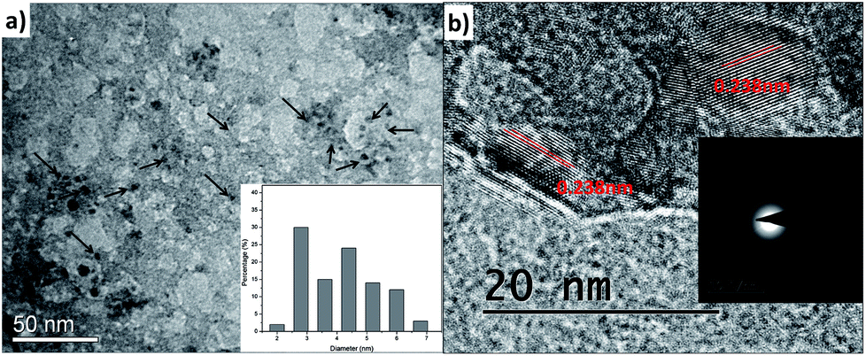 | ||
| Fig. 3 (a) and (b) TEM micrographs of as-synthesized C2 at different scales with lattice fringe analysis; inset of (a) and (b) are size distribution and SAED pattern respectively. | ||
3.2 Characterization of amine functionalized C1N and C2N
The morphology and size of C1N and C2N were done by TEM and DLS. The TEM micrographs of C1N and C2N are shown in Fig. S3a and S3b† respectively. It is perceived that there is no remarkable change in size and morphology of C1 and C2 after amine functionalization. The C1N and C2N are still having spherical shape, well dispersity and uniform size.The absorption study of C1, C2, C1N and C2N in aqueous medium was conducted using UV visible spectroscopy as presented in Fig. 4. C1 and C2 display the absorption band in the ultraviolet region due to the absorption of the aromatic π system or the n–π* transition of carbonyl groups which indicate the CQDs synthesis from soot (Fig. 4a). In the absorption spectra of EDA, the peaks at higher wavelengths 339 nm and 378 nm are mainly due to the presence of C–N of amines.29–31
 | ||
| Fig. 4 (a) Absorption spectra of C1, C2, C1N and C2N; and (b) quantum yield of C1, C2, C1N and C2N. | ||
C1 absorbs at 220 nm while after amine functionalization of C1 with EDA (C2:EDA: 1:1 v/v), the absorption peaks observed at 240 nm, 272 nm and 342 nm indicates the π–π* transition of the π-orbitals of aromatic carbon (C![[double bond, length as m-dash]](https://www.rsc.org/images/entities/char_e001.gif) C bond), n–π* transition of the CO and CN bond present in C1N QDs, respectively.32,33 The absorption in lower UV region is mainly due to polycyclic aromatic hydrocarbon (PAHs) with large energy band gaps (two or three ringed PAH).34
C bond), n–π* transition of the CO and CN bond present in C1N QDs, respectively.32,33 The absorption in lower UV region is mainly due to polycyclic aromatic hydrocarbon (PAHs) with large energy band gaps (two or three ringed PAH).34
In the absorption spectra of C2, the broad peak from 262 nm to higher wavelength 300 nm, indicates the π–π* transition of the π-orbitals of aromatic CC bond merged with the n–π* transition of CO bond due to the possibly high carbonization by the oxidant, nitric acid during the synthesis of C2.29–33 While after the treatment of C2 with (15 μM) EDA (C2:EDA: 40:1 v/v) a new peak at 337 mn is credited to the n–π* transition of CN bond which confirms the presence of nitrogen on the C2N surface. Moreover, after C2:EDA: 1:1 v/v treatment, the increase in intensity and shifting of peak at 337 mn to 342 nm indicates the increase in nitrogen groups on the C2N surface.29–33
This phenomenon lies on the fact that some auxochromes like amine groups that present on CQDs can result in the absorption peak at longer wavelengths. Therefore, the nitrogen containing unshared/lone pair of electrons could have reacted with the CC bonds which alone absorb at 280 nm, while bonded together with nitrogen or oxygen (CN and/or CO) absorbs at around 350 nm. This phenomenon is involved in the structure of CQDs.35
The QY of these QDs was calculated using QS dye as reference (Fig. 4b). C1 exhibited the remarkable QY of ∼5.63% in comparison to C2 which delivers QY of 3.25%. After their treatment with EDA, there was an increase in their QY i.e. from 5.63% of C1 to 12.7% for C1N and from 3.25% of C2 to 8.48% for C2N QDs. That can be attributed to the presence of auxochrome nitrogen having lone pair of electrons, on their surfaces after EDA treatment. The QY is approximate to here mention other works on CQDs synthesis from various other waste precursors in Table 1. In addition, our approach is expeditious, simplistic, and economic and utilizes one of the hazardous pollutant materials, vehicle soot as a precursor.
| Precursor | Synthesis | QY% | Application | Reference |
|---|---|---|---|---|
| Soy milk | Hydrothermal | 0.026 | Electrocatalysis | 13 |
| Sugarcane juice | Hydrothermal | 0.057 | Cell-imaging | 14 |
| Coffee | DI water, centrifugation | 5.5 | Cell-imaging | 15 |
| Egg yolk | Plasma-induced pyrolysis | 5.96 | Fluorescent ink | 16 |
| Dextrin | H2O + H2SO4, microwave-assisted | 4.8–8.4 | Cell imaging | 17 |
| Vehicle soot | Water | 5.63 | TNT sensing | This work |
| Nitric acid | 3.25 |
Upon excitation of 2 mL C1 at different λex (from 220 nm to 370 nm), it is observed that C1 shows highest emission intensity at λex = 240 nm (λem = 396 nm) which is due to the participation of CC of aromatic carbons along with little possible CO groups present in C1 QDs (Fig. 5a). The decrease in PL-intensity with increase in excitation wavelength can be targeted to a decrease in the absorption for higher wavelengths as shown in its absorption spectra.
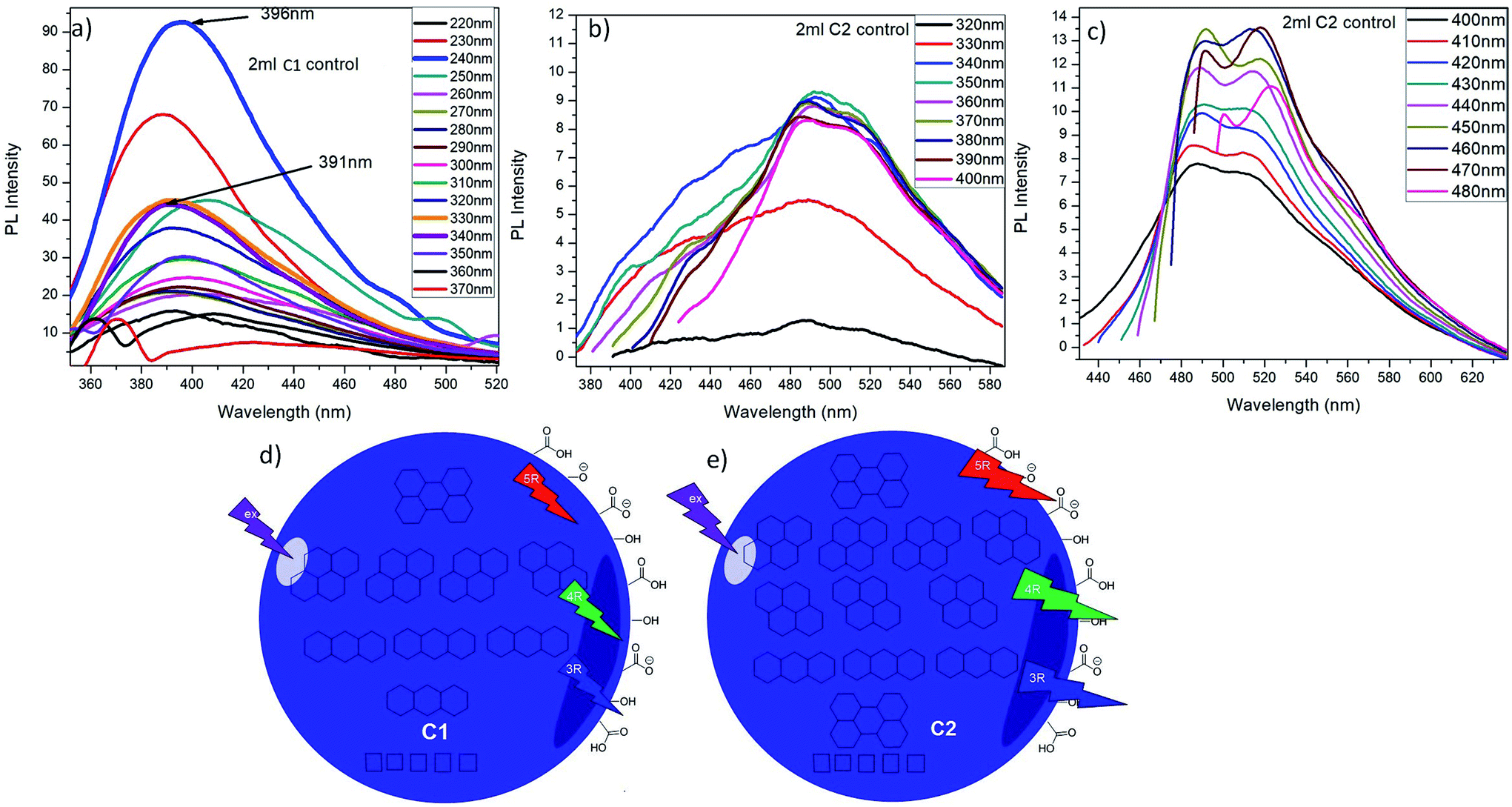 | ||
| Fig. 5 Showing the PL emission spectra of (a) C1; (b) and (c) C2 at different excitation wavelengths; (d) and (e) are the proposed compositions of C1 and C2 respectively on the basis of the number of rings in PAHs. | ||
2 mL C2 solution was also excited at λex from 320 nm to 480 nm. It was observed that C2 exhibit wavelength dependent emission behaviour i.e. from excitation wavelength 320 nm to 480 nm, the emission wavelength red shift from 491 nm to 516 nm (Fig. 5b and c). For λem = 491 nm and 516 nm, the excitation wavelength are 350 nm and 420 nm respectively that might be due to maximum numbers of particles are excited at λex = 350 nm and 420 nm, resulting in maximum emission intensity. This red shift in emission behaviour could be attributed with the degree of oxidation and presence of multiple emission centres in these CQDs.36
Increasing the excitation wavelength has two striking effects on CQDs emission: a noteworthy decrease of the PL-intensity and a robust red shift.34 Here also, it can be noticed that, with increase in excitation wavelength, the overall emission intensity at λem = 491 nm goes on decreasing while the intensity at λem = 516 nm keeps on increasing. The emission at lower excitation wavelength can be ascribed to C2 individual molecule singlet emission (singlet emission bands). When the excitation wavelength is increased from 400 nm to 480 nm, two emission bands at 491 nm and 516 nm started narrowing. When the excitation wavelength is increased up to 480 nm, these two becomes well-resolved peaks out of those bands at lower excitation wavelength. These bands are named as lower energy (LE) bands.34 It also indicates the presence of multiple absorption states in the sample which leads in the emission at higher wavelength. Exciting the CQDs at these secondary maxima led to intense asymmetric emission spectra with emission maxima at 516 nm. These results elucidate that there are several different PAH molecules exist in the CQDs that are optically active in the spectral region of interest, and possible energy transfer happens between them.34 The main emission, might resulted from self-trapped excitons in PAHs while, the emission at longer wavelengths is likely emitted by PAHs with smaller energy band gaps.
It is reported that at shorter wavelengths (<400 nm) principally the three and four-ringed PAH (PAH-3R and PAH-4R respectively) are excited and either emits directly or, to a lesser scale, transfer energy to five-ringed PAH (PAH-5R).34 That might be due to the fact that at shorter wavelengths PAH-5R do not absorb strongly so, the PAH-3R/4R might transfer their energy to the PAH-5R that account for the long emission tail seen at higher wavelengths. Upon the increase in λex to 400 nm, all the PAHs (PAH-3R, PAH-4R and PAH-5R) can be excited directly, leads in red shift of emission wavelength. Beyond this (λex > 400 nm), the PAH-3R and PAH-4R show less absorption and while the PAH-5Rexhibit increased absorption, resulting in a constant shift of the PL emission.34 This emission behaviour is in agreement with other foregoing published multicolour imaging applications of CQDs.34,37
So, it can be summarized that, C1 might be composed of PAHs as in order of PAH-3R > PAH-4R > PAH-5R; while, C2 might comprise of the PAHs as sequence of PAH-4R > PAH-3R > PAH-5R which are responsible for their specific emission behaviour. Both of the QDs are having lesser PAHs having lower band gap energies (PAH-5R), while the amount of PAH-4R is considerably higher in C2 than that of C1 as depicted from their emission profiles. This can be credited to the nitric acid treatment during the synthesis of C2. On the basis of this finding, the expected structure and their optical phenomenon of C1 and C2 are elucidated in Fig. 5d and e respectively. C1 and C2 dissolved in water solvent were observed to be stable at room temperature for at least eight months.
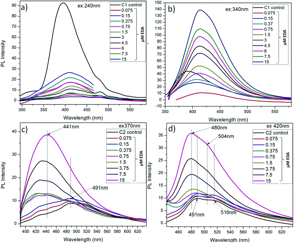
The amine capped CQDs were further characterized for their emission behaviour (Fig. 6). As discussed here, C1 were observed to possess higher emission intensity at λex = 240 nm but after EDA treatment, the maximum change in their emission intensity was observed at λex = 340 nm. So, these two excitation wavelengths were considered for assessment of change in emission intensity of C1 after amine functionalization (Fig. 6a and b). It was observed that at λex = 240 nm, there is decrease in emission intensity with the increase in EDA concentration and simultaneously, red shift in emission wavelength from λem = 396 nm in absence of EDA to λem = 414 nm in presence of 7.5 μM EDA. Concurrently, at λex = 340 nm, a continuous increase in emission intensity (λem = 414 nm) was observed with the increase in EDA concentration. Finally, there is approximate complete loss of C1 emission intensity in the presence of higher EDA (15 μM) concentration. It clearly depicts the involvement of oxygen-containing functional groups i.e. (CO)/C–OH at the surface of C1 in bonding with the amine groups of EDA leading in the net decrease in free CO/C–OH groups. Finally, it is assumed that in the presence of 15 μM EDA, approximate the entire free CO/C–OH groups are used in amine functionalization. The redshift and increase in emission intensity at λex = 240 nm and 340 nm (λem = 414 nm) respectively confirm the generation of C–N/CN groups on C1 surface.38
 | ||
| Fig. 6 Showing the PL emission spectra of C1 (a) and (b); C2 (c) and (d) in the presence of EDA at different excitation wavelengths respectively. | ||
As explained before, due to the different PAHs distribution in C2, they exhibit emission at higher wavelengths i.e. λem shifts from 491 nm to 516 nm with increase in λex from 320 nm to 480 nm. After EDA treatment, it is observed that at λex 370 nm and 420 nm, there is an increase in emission intensity and the remarkable shift in emission wavelength of C2 towards the short wavelength with the increase in EDA concentration (Fig. 6c and d). There is an extreme decrease in the carbon–carbon bonds (CC/C–C) with the increase in nitrogen-based dopant concentration.38 On the other side, the carbon-oxygen bonds ((CO)/C–OH) and carbon-nitrogen bonds (C–N/CN) increase with increase of the nitrogen-based dopant concentration. So, this observed increase in emission intensity of C2 after EDA treatment, can be attributed to the generation of C–N/CN bonds on C2 surface after EDA treatment.9,38 Along with, the shifting of maximum emission peak toward the short wavelength might be due to the decrease in CC/C–C bonds with the increase in EDA concentration which could have change in PAHs distribution in C2 as: PAH-3R > PAH-4R.
The work reported in literature (ref. 39–43) explain different mechanism for the strong photoluminescence of luminescent carbon dots but convincing photoluminescence mechanism is still unclear. In present work QD were functionalized with EDA to subject amine group on their surface using different concentration of EDA maintained at pH in the range of 6.5–7. In protonated EDA-QDs, a cyclic structure might have formed through the H-bonding between NH3+ and the oxygen atom of the amide bond. Moreover, explanation for possible presence and distribution of PAHs in CQDs were already have been discussed in manuscript. These conjugated polyaromatic structure are involved in this EDA mediated CQDs emission enhancement. The cyclic structure formed by protonated EDA might have aided the indirect proton transfer from NH3+ to the conjugated PAHs through the carboxyl groups. This proton transfer would have prevented the charge transfer in the excited state resulting in the recovery of fluorescence.9
So, it can be summarized that EDA terminal nitrogen contributes its extra electrons into the π-electron system of CQDs through the carboxyl groups and instigate a change in the densities of π states.44 It may result to an increment of the energy states density near the Fermi levels which enhances the emission intensities in the C1N and C2N. The proposed explanation is also evidenced by the work reported by Z. Qian et al.9
These N-capped CQDs (C1N and C2N) are then inspected for TNT detection. Since, the electron deficient ring of TNT can form JM complex with the amine groups of EDA, so this complex is explored for the overlapping behaviour between the absorption spectrum of JM complex and the emission spectrum of C1N in the presence of TNT. Fig. 7a shows the possible overlapping of absorbance spectrum of EDA/TNT (JM complex) with the emission spectra of C1, C1N and C1NT (220 μM TNT). The broad absorption peak of EDA/TNT at longer wavelength confirms the formation of JM complex between amine groups of EDA and electron deficient ring of TNT. It unveils that due to good spectral overlapping between the absorbance of EDA/TNT (JM complex) with the emission of C1N, justifying that C1NT possess high tendency to quench the C1N emission. Fig. 7a shows the abrupt decrease in PL intensity of C1N on addition of 220 μM (50 ppm) TNT, which involves the surface amine groups capable to interact with TNT. The possible rationale behind this PL emission quenching relies on the formation of Meisenheimer complex (JM-complex) by electron-rich amine groups of C1N with electron deficient TNT aromatic ring. This JM complex (C1NT) absorbs at the emission wavelength of C1N. This behaviour is in successful approach for TNT detection using C1N.
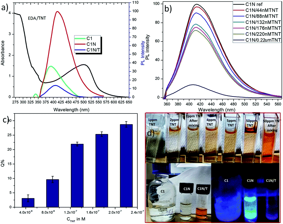 | ||
| Fig. 7 (a) Overlapping of absorbance spectra of EDA/TNT with emission spectra of C1, C1N and C1NT; (b) analytical performance of C1N towards TNT in 220 μM to 44 nM concentration range; (c) percentage quenching of C1N fluorescence in presence of TNT; and (d) photographs of C1N solutions in ambient light (upper panel) showing the colorimetric change with increase in TNT concentration and under UV illumination (lower right panel) in the absence and presence of TNT. | ||
Accordingly, a successive decrease in C1N emission intensity is spotted with the increase in TNT concentration from 44 nM to 220 μM in C1N solution at λex = 340 nm (Fig. 7b). The percentage quenching (Q%) can be demonstrated as:
The theoretical interpretation of the TNT detection capability of C1N in terms of detection limit (LOD), Stern–Volmer constant (KSV) and the association constant of C1N and TNT by Benesi–Hildebrand method is presented in Fig. 8a, b and c respectively. The LOD of C1N based probe towards TNT was determined using the relation of change in fluorescent intensity (I0 − I) at λem = 414 nm against TNT concentration (in M) (signal to noise ratio = 3) (Fig. 8a). The limit of detection is calculated using:
| ΔI = I0 − I = 1.557 × 10⁸C |
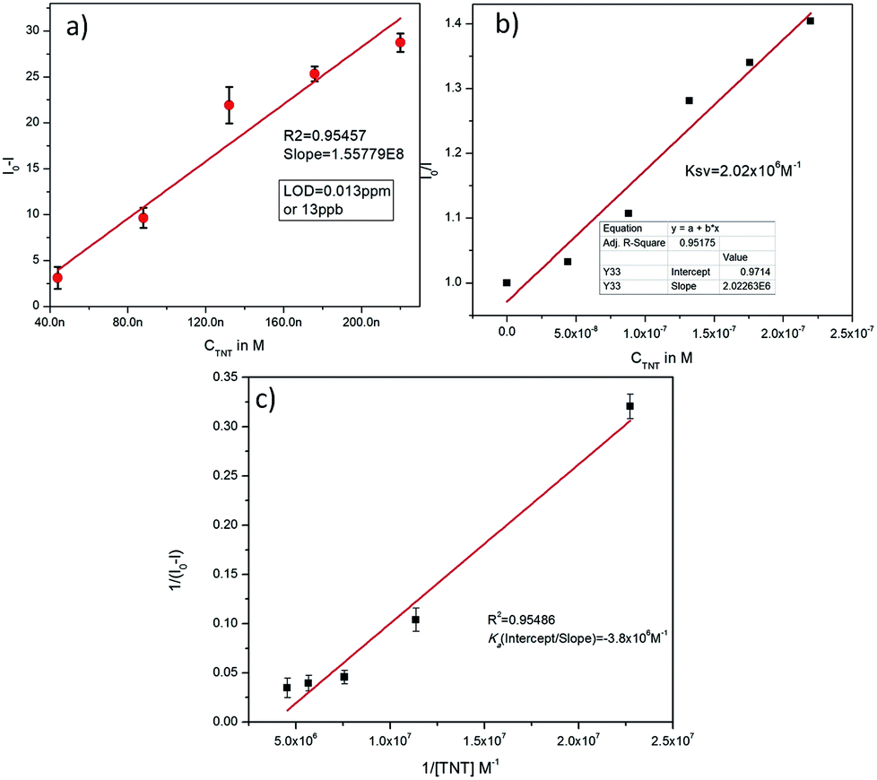 | ||
| Fig. 8 (a) Analysis of variation in fluorescence emission intensity of C1N towards TNT in 4.4 × 10⁻⁸ M to 2.2 × 10⁻⁷ M concentration range; (b) Stern–Volmer plot of C1N fluorescence against of TNT concentration; and (c) relation between 1/I0 − I and 1/TNT attributing the association constant of C1N and TNT by Benesi–Hildebrand method. | ||
Under the controlled conditions, the TNT induced PL quenching caused is excellently expressed by the Stern–Volmer equation:
The association constant of the TNT–C1N complex is determined by Benesi–Hildebrand method (Fig. 8c) from its PL emission quenching data following the equation:

Sustaining the same principle for TNT detection on the basis of JM complex formation with the amine groups present on CQDs surface, C2N was also explored for TNT detection (Fig. 9). In agreement with the C1N results, C2N emission intensity is also witnessed to decrease successively with the increase in TNT concentration from 4.4 × 10⁻⁸ M to 3.08 × 10⁻⁷ M (44 nM to 308 nM) concentration range at both the excitation wavelengths 370 nm and 420 nm (Fig. 9a and c). The Q% for C2N in the presence of TNT at λex = 340 nm and 420 nm are shown in the insets of Fig. 9b and d respectively. At the λex = 340 nm, the net Q% of the C2N emission intensity by TNT is found to be about 15.55% and 9.29% at 2.64 × 10⁻⁷ M (0.06 ppm) and 4.4 × 10⁻⁸ M (0.01 ppm) TNT concentrations respectively (Fig. 9b inset). While at the λex = 420 nm, the aggregate Q% of the C2N emission intensity by TNT is about 21.64% and 16.25% at 2.64 × 10⁻⁷ M (0.06 ppm) and 8.8 × 10⁻⁸ M (0.02 ppm) TNT concentrations respectively (Fig. 9d inset). In inferior to the C1N, there is no visible colorimetric change in C2N solution upon the addition of TNT. As explained here, there is only the change in C2N PL emission intensity in the presence of TNT due to quenching phenomenon.
 | ||
| Fig. 9 (a) and (c) Analytical performance of C2N towards TNT in 3.08 × 10⁻⁷ M to 4.4 × 10⁻⁸ M concentration range at λex 370 nm and 420 nm respectively; (b) and (d) analysis of variation in fluorescence emission intensity of C2N towards TNT for LOD determination; inset of (b) and (d): Q% of C2N fluorescence in presence of TNT at λex 370 nm and 420 nm respectively. | ||
The LOD of C2N nanoprobe respecting TNT is also evaluated using the relation between I0 − I at emission wavelengths 447 nm (for λex = 370 nm) and 498 nm (λex = 420 nm) against TNT concentration (in M) (n = 3) as shown in Fig. 9b and d respectively. At both the λex, a clear linear decrease in C2N emission intensity due to TNT is observed.
At λex = 370 nm, the linear TNT concentration range is 4.4 × 10⁻⁸ M to 2.64 × 10⁻⁷ M while, at λex = 420 nm, it is 8.8 × 10⁻⁸ M to 2.64 × 10⁻⁷ M. Their linear regression equation can be represented as:
At λex = 370 nm: (R2 = 0.9752; SD is ±0.13),
| ΔI = I0 − I = 8.027 × 10⁶C. |
At λex = 420 nm: (R2 = 0.996; SD is ±0.0512),
| ΔI = I0 − I = 7.013 × 10⁶C |
The KSV and Ka of C2N in the presence of TNT at both the excitation wavelengths (λex 370 nm and 420 nm) are also calculated as presented in Fig. 10. When I0/I is plotted against the TNT concentration (in M), the KSV for C1N, at λex 370 nm is calculated as 0.38 × 10⁶ M−1 (R2 = 0.96994) in the concentration range of is 4.4 × 10⁻⁸ M to 2.64 × 10⁻⁷ M (Fig. 10a) while at λex 420 nm, it is found to be 0.48 × 10⁶ M−1 (R2 = 0.99428) in the concentration range of is 8.8 × 10⁻⁸ M to 2.64 × 10⁻⁷ M (Fig. 10c). The Ka value for C2N with TNT at λex 370 nm and 420 nm are found as 11.08 × 10⁶ M−1 (Fig. 10b) and 21.5 × 10⁶ M−1 (Fig. 10d) respectively. These high values of Ka for C1N and C2N implicate their high sensitivity towards TNT. This experimental data certainly enlightens the effective energy transfer between nitrogen capped CQDs and JM complex in the solution leading to increased fluorescence quenching.
 | ||
| Fig. 10 (a) and (c) Stern–Volmer plot of C2N fluorescence against of TNT concentration at λex 370 nm and 420 nm respectively; (b) and (d) relation between 1/I0 − I and 1/TNT attributing the association constant of C2N and TNT at λex 370 nm and 420 nm respectively by Benesi–Hildebrand method. | ||
The comparison of C1N and C2N (at λex 370 nm and 420 nm) in the terms of different theoretical properties among each other is shown in Table S1.† The LOD and KSV for both the C1N and C2N are in the vicinity of or lower than the most sensitive reported fluorescent quenching methods as listed in Table 2.
| S. No. | System | LOD | KSV | Ref. |
|---|---|---|---|---|
| 1 | Vehicle soot derived CQDs | ∼4.9 ppb | 0.48 × 10⁶ M−1 | This work |
| 2 | Oligohistidine–CdSe–ZnS QDs | 19.98 ppb | 0.17 × 10⁶ M−1 | 45 |
| 3 | Poly(p-phenylenevinylene)/mesoporous silica nanoparticles | 136 ppb | 0.011 × 10⁶ M−1 | 46 |
| 4 | Graphene QDs | 490 ppb | 8 × 10³ M−1 | 47 |
| 5 | (FITC-β-cyclodextrin) | 4.5 ppb | 0.379 × 10⁶ M−1 | 48 |
| 6 | Porphyrin-doped mesoporous silica | 10 ppb | Not studied | 49 |
The amine-terminated compound (EDA) acts as surface passivating agent for CQDs. The surface passivation is required for the enhanced photoluminescence (PL) of the CQDs.27 The reason for enhanced sensitivity might be that we modified the CQDs surface with short length EDA molecules. It is known that the resultant spacer length in several nanometers around nanoparticles surface has an adverse effect on the energy transfer efficiency between donor and acceptor.50 The choice of EDA for the modification of CQDs surface is crucial, because it not only allows a compact surface structure but also provides higher binding sites for TNT molecules to form JM complex.45 The strong donor–acceptor (D–A) interactions between the JM complex formed by TNT with the EDA at the CQDs surface induced significant quenching in CQDs emission and enabled easily detection of ultra-trace TNT.
The XRD spectra and Raman spectra are shown and discussed in Fig. S2 of ESI.† The TEM micrographs of C1N and C2N are shown in Fig. S3.† The hydrodynamic size and surface potentials of C1 and C2 before and after amine functionalization were measured by DLS and shown in Fig. S4 and S5† respectively. The FTIR study was conducted to confirm the EDA functionalization of C1, C2 QDs and their interactions with TNT as discussed in ESI (Fig. S6†). The EDX data is shown in Fig. S7.† The systematic execution of C1N and C2N concerning their selectivity towards TNT was also conducted against some of the very common interfering TNT analogues such as DNT, 2-TA, and NB which is also discussed in ESI (Fig. S8†). Owing to the high sensitivity and selectivity delivered by these CQDs probes (C1N and C2N), their feasibility was also vindicated against real tap water samples (CSIO) impaled with TNT [data shown in Table S2†]. The cell compatibility study (MTT assay) and their potential for TNT detection in cells is also discussed in ESI (Fig. S9†).
4. Conclusions
Vehicle soot, one of the hazardous pollutants has been explored as starting material for CQDs synthesis with a facile hydrothermal method. The CQDs has been synthesized in the absence and presence of oxidant, HNO3 to check the influence of presence of oxidant on the emission profile of these CQDs. The as-synthesized CQDs were amine functionalized using EDA as capping agent. A remarkable increase in their QY was observed after EDA treatment. The presence of nitrogen moieties on CQDs surface was confirmed by UV, PL and FTIR spectroscopy. It was expected that, C1 might be composed of PAHs as in order of PAH-3R > PAH-4R > PAH-5R; while, C2 might comprise of the PAHs as sequence of PAH-4R > PAH-3R > PAH-5R which are responsible for their specific emission behaviour. The amine groups present on C1N and C2N surfaces were involved in the formation of Meisenheimer complex with TNT for its monitoring in spiked water up to sub-ppb level (minimum ∼4.97 ppb TNT). Both the C1N and C2N (at λex = 370 nm and λex = 420 nm) exhibited high sensitivity and selectivity towards TNT with higher values of both the KSV and Ka. The results are in line with the waste to wealth approach (soot to shine), wherein the hazardous pollutant vehicle product is approached as a detection probe for explosive sensing. The study also documented the applicability of these CQDs for intracellular TNT detection.Conflicts of interest
Authors declare that there is not any conflict of interest.Acknowledgements
The authors acknowledge Director, CSIR-CSIO, Chandigarh for his kind permission to perform this work.References
- J. T. Hardy, Climate change: causes, effects, and solutions, John Wiley & Sons, 2003 Search PubMed.
- H. Feng and Z. Qian, The Chemical Record, 2018, 18, 491–505 CrossRef PubMed.
- G. Chen, H. Feng, X. Jiang, J. Xu, S. Pan and Z. Qian, Anal. Chem., 2018, 90, 1643–1651 CrossRef PubMed.
- C. Tang, J. Zhou, Z. Qian, Y. Ma, Y. Huang and H. Feng, J. Mater. Chem. B, 2017, 5, 1971–1979 RSC.
- J. Hou, H. Cheng, C. Yang, O. Takeda and H. Zhu, Nano Energy, 2015, 18, 143–153 CrossRef.
- Y.-Q. Zhang, D.-K. Ma, Y.-G. Zhang, W. Chen and S.-M. Huang, Nano Energy, 2013, 2, 545–552 CrossRef.
- C.-B. Ma, Z.-T. Zhu, H.-X. Wang, X. Huang, X. Zhang, X. Qi, H.-L. Zhang, Y. Zhu, X. Deng and Y. Peng, Nanoscale, 2015, 7, 10162–10169 RSC.
- D. G. Babar, S. K. Sonkar, K. M. Tripathi and S. Sarkar, J. Nanosci. Nanotechnol., 2014, 14, 2334–2342 CrossRef PubMed.
- Z. Qian, J. Ma, X. Shan, L. Shao, J. Zhou, J. Chen and H. Feng, RSC Adv., 2013, 3, 14571–14579 RSC.
- J.-e. Park, E. D. Grayfer, Y. Jung, K. Kim, K.-K. Wang, Y.-R. Kim, D. Yoon, H. Cheong, H.-E. Chung and S.-J. Choi, J. Mater. Chem. B, 2013, 1, 1229–1234 RSC.
- X. T. Zheng, H. L. He and C. M. Li, RSC Adv., 2013, 3, 24853–24857 RSC.
- S. Devi, A. Kaur, S. Sarkar, S. Vohra and S. Tyagi, Integr. Ferroelectr., 2018, 186, 32–39 CrossRef.
- C. Zhu, J. Zhai and S. Dong, Chem. Commun., 2012, 48, 9367–9369 RSC.
- V. N. Mehta, S. Jha and S. K. Kailasa, Mater. Sci. Eng., C, 2014, 38, 20–27 CrossRef PubMed.
- C. Jiang, H. Wu, X. Song, X. Ma, J. Wang and M. Tan, Talanta, 2014, 127, 68–74 CrossRef PubMed.
- J. Wang, C. F. Wang and S. Chen, Angew. Chem., Int. Ed., 2012, 51, 9297–9301 CrossRef PubMed.
- N. Puvvada, B. N. P. Kumar, S. Konar, H. Kalita, M. Mandal and A. Pathak, Sci. Technol. Adv. Mater., 2012, 13, 045008 CrossRef PubMed.
- S. Devi, R. Kaur, B. Singh, A. K. Paul and S. Tyagi, J. Nanosci. Nanotechnol., 2018, 18, 6838–6849 CrossRef PubMed.
- S. Devi, B. Singh, A. Paul and S. Tyagi, Anal. Methods, 2016, 8, 4398–4405 RSC.
- S. Devi, R. Kaur, A. K. Paul and S. Tyagi, Colloid Polym. Sci., 2018, 1–4 Search PubMed.
- Q. Sun, S. Fang, Y. Fang, Z. Qian and H. Feng, Talanta, 2017, 167, 513–519 CrossRef PubMed.
- H. Ao, H. Feng, X. Huang, M. Zhao and Z. Qian, J. Mater. Chem. C, 2017, 5, 2826–2832 RSC.
- S. Hughes, S. S. Dasary, S. Begum, N. Williams and H. Yu, Sens. Bio-Sens. Res., 2015, 5, 37–41 CrossRef PubMed.
- M. Wanko, J. Houmøller, K. Støchkel, M.-B. S. Kirketerp, M. Å. Petersen, M. B. Nielsen, S. B. Nielsen and A. Rubio, Phys. Chem. Chem. Phys., 2012, 14, 12905–12911 RSC.
- A. Bailey and S. G. Murray, Propellants, Explos., Pyrotech., 1989, 21–47 Search PubMed.
- H. Peng and J. Travas-Sejdic, Chem. Mater., 2009, 21, 5563 CrossRef.
- Y. Wang and A. Hu, J. Mater. Chem. C, 2014, 2, 6921–6939 RSC.
- Y. Dong, R. Wang, H. Li, J. Shao, Y. Chi, X. Lin and G. Chen, Carbon, 2012, 50, 2810–2815 CrossRef.
- L. Wang and H. S. Zhou, Anal. Chem., 2014, 86, 8902–8905 CrossRef PubMed.
- R. Zhang and W. Chen, Biosens. Bioelectron., 2014, 55, 83 CrossRef PubMed.
- Y. Jiang, Q. Han, C. Jin, J. Zhang and B. Wang, Mater. Lett., 2015, 141, 366–368 CrossRef.
- R. Liu, H. Li, W. Kong, J. Liu, Y. Liu, C. Tong, X. Zhang and Z. Kang, Mater. Res. Bull., 2013, 48, 2529–2534 CrossRef.
- Y. Zhuo, H. Miao, D. Zhong, S. Zhu and X. Yang, Mater. Lett., 2015, 139, 197–200 CrossRef.
- M. Fu, F. Ehrat, Y. Wang, K. Z. Milowska, C. Reckmeier, A. L. Rogach, J. K. Stolarczyk, A. S. Urban and J. Feldmann, Nano Lett., 2015, 15, 6030–6035 CrossRef PubMed.
- Y. Zhang, Y. Wang, X. Feng, F. Zhang, Y. Yang and X. Liu, Appl. Surf. Sci., 2016, 387, 1236–1246 CrossRef.
- S. Zhu, Y. Song, X. Zhao, J. Shao, J. Zhang and B. Yang, Nano Res., 2015, 8, 355–381 CrossRef.
- L. Chunduri, A. Kurdekar, S. Patnaik, B. V. Dev, T. M. Rattan and V. Kamisetti, Mater. Focus, 2016, 5, 55–61 CrossRef.
- S. R. M. Santiago, Y. A. Wong, T.-N. Lin, C.-H. Chang, C.-T. Yuan and J.-L. Shen, Opt. Lett., 2017, 42, 3642–3645 CrossRef PubMed.
- Y.-P. Sun, B. Zhou, Y. Lin, W. Wang, K. A. S. Fernando, P. Pathak, M. J. Meziani, B. A. Harruff, X. Wang, H. F. Wang, P. G. Luo, H. Yang, M. E. Kose, B. L. Chen, L. M. Veca and S.-Y. Xie, J. Am. Chem. Soc., 2006, 128, 7756–7757 CrossRef PubMed.
- J. G. Zhou, C. Booker, R. Y. Li, X. T. Zhou, T.-K. Sham, X. L. Sun and Z. F. Ding, J. Am. Chem. Soc., 2007, 129, 744–745 CrossRef PubMed.
- D. Y. Pan, J. C. Zhang, Z. Li and M. H. Wu, Adv. Mater., 2010, 22, 734–738 CrossRef PubMed.
- A. B. Bourlinos, A. Stassinpoulos, D. Anglos, R. Zboril, M. Karakassides and E. P. Giannelis, Small, 2008, 4, 455–458 CrossRef PubMed.
- Z. S. Qian, J. Zhou, J. J. Ma, X. Y. Shan, C. C. Chen, J. R. Chen and H. Feng, J. Mater. Chem. C, 2013, 1, 307–314 RSC.
- Z. Luo, S. Lim, Z. Tian, J. Shang, L. Lai, B. MacDonald, C. Fu, Z. Shen, T. Yu and J. Lin, J. Mater. Chem., 2011, 21, 8038 RSC.
- E. R. Goldman, I. L. Medintz, J. L. Whitley, A. Hayhurst, A. R. Clapp, H. T. Uyeda, J. R. Deschamps, M. E. Lassman and H. Mattoussi, J. Am. Chem. Soc., 2005, 127, 6744–6751 CrossRef PubMed.
- S. Xu, H. Lu, J. Li, X. Song, A. Wang, L. Chen and S. Han, ACS Appl. Mater. Interfaces, 2013, 5, 8146–8154 CrossRef PubMed.
- L. Fan, Y. Hu, X. Wang, L. Zhang, F. Li, D. Han, Z. Li, Q. Zhang, Z. Wang and L. Niu, Talanta, 2012, 101, 192–197 CrossRef PubMed.
- L. Feng, C. Tong, Y. He, B. Liu, C. Wang, J. Sha and C. Lü, J. Lumin., 2014, 146, 502–507 CrossRef.
- S. Tao and G. Li, Colloid Polym. Sci., 2007, 285, 721–728 CrossRef.
- Y. Xia, L. Song and C. Zhu, Anal. Chem., 2011, 83, 1401–1407 CrossRef PubMed.
Footnote |
| † Electronic supplementary information (ESI) available. See DOI: 10.1039/c8ra06460a |
| This journal is © The Royal Society of Chemistry 2018 |