DOI:
10.1039/C8RA06437G
(Paper)
RSC Adv., 2018,
8, 35343-35347
Nanoscale tungsten nitride/nitrogen-doped carbon as an efficient non-noble metal catalyst for hydrogen and oxygen recombination at room temperature in nickel–iron batteries†
Received
31st July 2018
, Accepted 1st October 2018
First published on 15th October 2018
Abstract
A nanoscale tungsten nitride/nitrogen-doped carbon (WN/NC) catalyst was synthesized through a facile route, and it exhibited efficient catalytic performance for hydrogen and oxygen recombination at room temperature with an average catalytic velocity of 140 μmol h−1 gcat−1 and long catalytic life of 954![[thin space (1/6-em)]](https://www.rsc.org/images/entities/char_2009.gif) 660 s without decay in the catalytic performance. With the WN/NC catalyst, a nickel–iron battery could be sealed and maintenance-free, and it also exhibited low cost; thus, the nickel–iron battery can be used for large-scale energy storage systems in rural/remote areas.
660 s without decay in the catalytic performance. With the WN/NC catalyst, a nickel–iron battery could be sealed and maintenance-free, and it also exhibited low cost; thus, the nickel–iron battery can be used for large-scale energy storage systems in rural/remote areas.
1. Introduction
To reduce greenhouse gas emission and consumption of non-renewable fossil fuels, developing clean energy has already become a global mission. Batteries have been considered the most suitable devices for energy storage systems for solar and wind energies. Large-scale batteries have been widely discussed for use in these fields, and these include lead-acid and lithium-ion batteries. Safety, low cost, long cycle life and being maintenance-free are the basic requirements of batteries for energy storage systems in rural/remote areas. Although lithium-ion batteries are highly efficient, they are expensive and can be unsafe due to flammability of organic electrolytes and high reactivity of Li-containing electrode materials.1,2 In contrast, aqueous rechargeable batteries satisfy safety concerns owing to their use of an aqueous electrolyte. Lead-acid batteries have limitations owing to the toxicity of lead to humans and environment and short cycle life.3,4 A nickel–iron battery is a safe, robust and durable power source with a long cycle life of 3000 cycles, and its calendar life is about 20 years even under abusive usage.3,4 Importantly, both Ni and Fe are abundant on earth and relatively nontoxic. A nickel–iron battery is highly desirable for energy storage.
The electrochemistry of an iron electrode in alkaline batteries involves the redox process of iron(II) hydroxide and metallic iron:3
| | |
Fe(OH)2 + 2e− ⇌ Fe + 2OH− E0 = −0.877 V vs. SHE
| (1) |
Meanwhile, the electrode potential for the hydrogen evolution reaction (eqn (2)) is positive to that of the iron electrode reaction; this can lead to the evolution of hydrogen gas during charging, due to which the nickel–iron battery cannot be sealed. Simultaneously, electrolyzation of water results in the loss of the aqueous electrolyte, due to which the battery needs refilling of water at regular intervals.4,5
| | |
2H2O + 2e− → H2 + 2OH− E0 = −0.828 V vs. SHE
| (2) |
Extensive research has been conducted to hinder hydrogen evolution, but a complete suppression of hydrogen evolution through modified iron materials and electrolytes appears to be a formidable challenge.5–7 Hariprakash et al.8 assembled a sealed nickel–iron battery with ceria-supported platinum as a hydrogen–oxygen recombinant catalyst. The battery showed negligible decay in its capacity during life-cycle tests. However, the usage of the noble metal catalyst can increase the price of the nickel–iron battery. Thus, if some non-noble metal catalysts can be used to recombine hydrogen and oxygen gases back to water, the battery can be sealed and maintenance-free, and it can also exhibit excellent cost performance.
Transition metal carbides and nitrides as non-noble metal catalysts have been investigated in the fields of catalysis since Levy and Boudart found in 1973 that tungsten carbides displayed platinum-like behaviour in surface catalysis.9 Extensive studies have shown that transition metal carbides and nitrides are catalytically active for reactions such as methanation of CO,10 conversion of methane to synthesis gas,11 hydrogenolysis, dehydrogenation and isomerization,12 hydrodenitrogenation,13 ammonia synthesis,14 hydroprocessing,15 NO dissociation and reduction with hydrogen,16 hydrogen evolution reaction,17 oxygen reduction reaction,18 deoxygenation,19,20 and ammonia decomposition.21 However, this was never used in a nickel–iron battery to combine hydrogen and oxygen gases generated in the charging process. Herein, a nanoscale tungsten nitride/nitrogen-doped carbon (WN/NC) catalyst was synthesized through a facile route, and it exhibited efficient catalytic performance for hydrogen and oxygen recombination at room temperature in a nickel–iron battery.
2. Experiment
2.1 Material preparation
Tungsten chloride (3.97 g, WCl6) was added to 20 mL ethanol with vigorous stirring for about thirty minutes, producing W-orthoester. Next, 4.2 g of urea was added to the obtained W-orthoester solution and stirred until urea was completely dissolved. Subsequently, the viscous solution was dried at 90 °C to remove residual solvent followed by loading into a tube furnace and heating under an argon atmosphere at 800 °C for 4 h with a ramp rate of 10 °C min−1. The objective products were obtained.
2.2 Sample characterizations
The phase structure of the obtained samples was identified by an X-ray diffractometer (XRD, DANDONGFANGYUAN, DX-2600X) utilizing Cu-Kα1 source with a step of 0.04°. The composition and chemical state of each element on the surface of WN particles were examined by X-ray photo electron spectroscopy (XPS) on a spectrometer (Kratos Axis Ultra DLD) using an Al Kα X-ray source (1486 eV). Raman spectra of the as-synthesized samples were collected by micro-Raman spectroscopy (Renishaw inVia reflex) at an excitation wavelength of 532 nm under ambient conditions. Particle size distribution and morphology of the catalysts were investigated using transmission electron microscopy (TEM) and high-resolution transmission electron microscopy (HRTEM) (FEI Tecnai G2 F20) operated at 200 kV.
2.3 Cell assembly and catalytic performance test
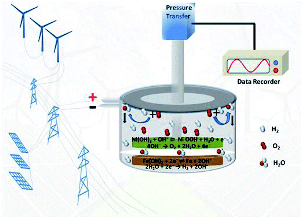
The iron electrode consisted of 93 wt% active materials (powders from Sichuan Changhong Battery Co., Ltd; XRD pattern of the powders is presented in ESI Fig. S1†), 5 wt% acetylene carbon black, and 2 wt% polytetrafluoroethylene (PTFE, 60 wt%, in diluted emulsion). The above materials were mixed and dispersed in ethanol to form a homogeneous slurry followed by loading into an Ni foam sheet. After drying in an oven at 65 °C for 6 h, the pasted plate was cut to several circular electrodes. The prepared iron electrode and excessive commercial Ni(OH)2 electrode were placed in a stainless-steel box as the anode and cathode, respectively. An aqueous solution of 6 M KOH + 15g L−1 LiOH was used as the electrolyte in the battery system. The box can be sealed with a pressure sensor on the top to monitor the pressure of the battery. The WN/NC catalyst (39 mg) was anchored in the air chamber of the battery to combine hydrogen and oxygen to water, which can drop back to the electrolyte, making the battery sealed (Scheme 1). The galvanostatic charge–discharge tests were performed on a Land battery testing system −5 V/100 mA (LandCT2001A) at room temperature. Activation and normal cycles were carried out at a charge rate of 0.5C for 2.5 h and discharge rate of 0.2C to 1.2 V. The mechanism of the hydrogen and oxygen recombination on the surface of the WN/NC catalyst in the nickel–iron battery can be simulated by temperature-programmed desorption mass spectrometer test (TPD-MS) (AutoChem II 2920). The temperature was raised up to 300 °C from room temperature and then cooled down to room temperature again under an argon atmosphere to desorb the adsorbed substances on the surface of the as-prepared sample; after adsorbing under hydrogen/argon atmosphere (H2:Ar = 1:9 (v/v)) for 90 min, the sample was kept under argon atmosphere for 1 h until the baseline was steady. Finally, the temperature-programmed desorption mass spectrometer test was carried out from room temperature to 800 °C. The catalytic velocity of the catalyst was calculated by the declined pressure of the battery in unit time at the discharge process.
 |
| | Scheme 1 The device of sealed, maintenance-free nickel–iron battery with WN/NC catalyst for energy storage. | |
3. Results and discussion
The XRD pattern of the as-prepared catalyst is presented in Fig. 1a. The peaks at 2θ values of 37.6°, 43.8°, 63.6°, 76.4°, and 80.4° could be well-indexed to the standard WN phase (PDF no.75-1012), corresponding to the (111), (200), (220), (311) and (222) reflections of WN. There were no lines that could be assigned to tungsten oxides and carbides or metallic W, indicating that the WN material is phase-pure. High-resolution XPS spectra of each element of WN are shown in Fig. 1b–d. Two strong signals corresponding to W 4f7/2 and W 4f5/2 of WN were found at 32.9 and 34.9 eV (Fig. 1b), and another two peaks at 36.1 and 38.5 eV could be assigned to W 4f orbitals of the surface WOx passivation layer.19 The existence of WOx was not reflected in the XRD patterns, and this suggested that WOx found on the surface of the samples might be amorphous or possibly due to chemisorbed oxygen on the W surface. The presence of carbon atoms with different chemical states in WN could be found by deconvoluting C 1s signals into three Gaussian peaks. The sharp peak at a binding energy of 284.6 eV was assigned to C atoms in the graphitic structure.18 The value was very close to the standard one for graphite carbon (284.8 eV). The two small peaks at 285.3 and 286.5 eV could be indexed to the carbon from C–N bonds and C–O bonds.22 Interestingly, no C–W bond was formed. The N 1s spectra were deconvoluted into four peaks. The sharp peak at 397.7 eV was ascribed to N from N–W bond23 and the small peaks at 398.3, 400.2, 401.3 eV were ascribed to pyridinic, pyrrolic and graphitic nitrogen, respectively.24 This indicated that it is much easier for N to combine with W to form an N–W bond as compared to that observed for C in the synthesis process. Meanwhile, nitrogen-doped carbon was obtained from the calcination of urea, which could restrain the aggregation of WN nanoparticles effectively. From the Raman spectrum (ESI Fig. S2†), a D band at 1350 cm−1 and a G band at 1590 cm−1 for carbon materials were observed, and the intensity ratio of D band to G bond (ID/IG) was 1.01, demonstrating that many defects caused by nitrogen doping existed in the carbon; this was consistent with the results of XPS analysis. According to the quantification report from XPS analysis (Table 1), we can see that the atomic ratio of N and W on the surface of WN is 0.64, which indicated high concentration of nitrogen-deficient W atoms on the surface and these deficient sites can easily be filled by oxygen when exposed to oxygen gas to form W–O bonds. Thus, sharp peaks assigned to W–O bonds were observed in high-resolution XPS spectra of W 4f orbitals (Fig. 1b).
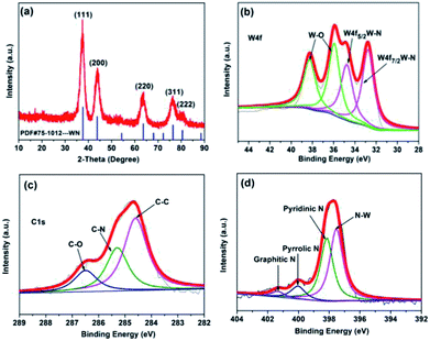 |
| | Fig. 1 (a) XRD patterns of the sample; high-resolution XPS spectra of each element of WN: (b) W 4f; (c) C 1s; (d) N 1s. | |
Table 1 Quantification report of the XPS analysis of WN
| Element |
W 4f |
N 1s |
O 1s |
C 1s |
Ratio of N/W |
| Atomic content (%) |
24.25 |
15.61 |
33.64 |
26.51 |
0.64 |
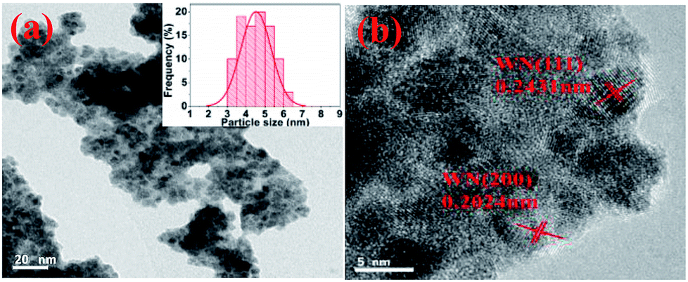
The TEM and HRTEM images of WN samples are shown in Fig. 2. The measured particle size distribution exhibits an average diameter of ca. 5 nm (Fig. 2a). From the high-resolution TEM (HRTEM) image (Fig. 2b), we infer that the interplanar distances of the small particles are 2.4 Å and 2.0 Å, corresponding to the (111) and (200) planes of WN. The existence of nitrogen-doped carbon (NC) in the sample can be seen from the TEM images; WN particles are supported on nitrogen-doped carbon (WN/NC).
 |
| | Fig. 2 (a) TEM image (inset: particle-size distribution of the corresponding samples); (b) HRTEM image. | |
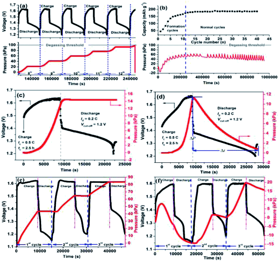
A sealed nickel–iron battery without catalyst was assembled to depict the regularity of gas evolution in the charge–discharge process. As can be seen from Fig. 3a and c, the pressure curve comprised two stages: one is the arc stage and another one is the plateau, which represented the varied trends of the pressure of the battery during the charge and discharge processes. When the battery was charged, hydrogen began to evolve slowly. As the charging process continued, the velocity of the hydrogen produced became increasingly faster (especially in the overcharge stage) until the charging process stopped. For the discharge stage, no hydrogen was generated, and the pressure was stable. After continuous cycling (Fig. 3a), the arc-plateau stage emerged repeatedly with the charge–discharge process, which increased the pressure of the battery. After five cycles, the pressure of the battery was at the degassing threshold of 100 kPa, which indicated that the nickel–iron battery cannot be sealed.
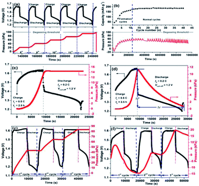 |
| | Fig. 3 The pressure versus state-of-charge results of a nickel–iron battery without catalyst: (a) 8–13th cycle; (c) 14th cycle; (e) 1st to 3rd cycle. The performance of the sealed, starved-electrolyte nickel–iron battery with WN catalyst: (b) the cycle performance and pressure of the battery; (d) pressure versus state-of-charge results of 14th cycles; (f) pressure versus state-of-charge results of 1st to 3rd cycles. All the tests were conducted at a charge rate of C/2 for 2.5 h and discharge rate of C/5 to cut-off voltage of 1.2 V. | |
After the WN/NC catalyst was anchored in the air chamber, the pressure of the battery could be controlled at pressures lower than the degassing threshold of 100 kPa even at the formation process (Fig. 3b). During the formation process, the capacity of the cell gradually increased as the cycles continued, and the pressure of the battery also increased. After that, the pressure of the battery declined gradually as the cycles continued. During the initial formation cycles (Fig. 3b and f), due to substantial inactive materials, the cathodic characteristic of the iron electrode was weak and hydrogen evolution was the predominant reaction, due to which considerable amount of hydrogen gas was generated during the charging process (20 kPa). Simultaneously, the time of discharge was short owing to the low charge capacity; the recombination of hydrogen and oxygen could not be carried out entirely in the discharging process, due to which the pressure of the battery declined slightly (4 kPa). All these phenomena resulted in increase in the pressure of the battery. However, for normal cycles (Fig. 3b and d), the iron electrode was already activated and the cathodic characteristic of the iron electrode became the predominant reaction; thus, the hydrogen gas generated in the charging process decreased (11 kPa). Correspondingly, there was sufficient time for recombination of hydrogen and oxygen in the discharge process because of higher charge capacity, due to which a pressure decrease of 11 kPa was observed. Thus, the pressure of the battery was stable with continuation of cycles. We can see that the battery with the WN/NC catalyst presented excellent cycle performance (Fig. 3b) compared to the battery without a catalyst (ESI, Fig. S3†). For the battery without catalyst, the highest discharge capacity after activation was 127 mA h g−1, which was much lower than 190 mA h g−1 of the battery with WN/NC catalyst. Additionally, the discharge capacity of the battery without catalyst decayed quickly after the formation process, but the battery with WN/NC catalyst exhibited stable discharge capacity of about 190 mA h g−1 as cycles were continued. In the starved-electrolyte nickel–iron battery, electrolyzation of water to hydrogen and oxygen gases decreased the amount of electrolyte, which led to poor cycle performance; with the nanoscale tungsten nitrides/nitrogen-doped carbon (WN/NC) catalyst, hydrogen and oxygen recombined to form water, which returned to the electrolyte. This indicated that the nickel–iron battery can be sealed and maintenance-free and can exhibit excellent cycle performance.
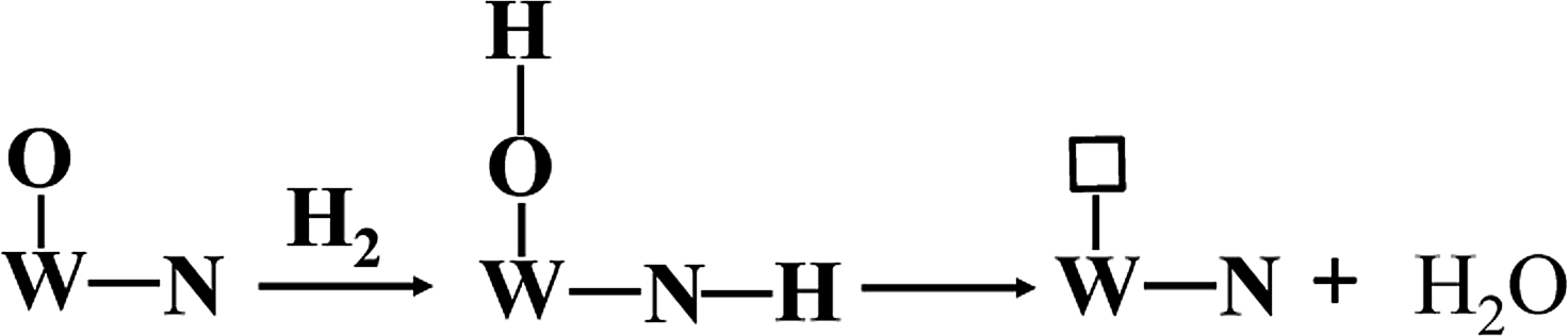
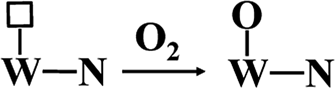
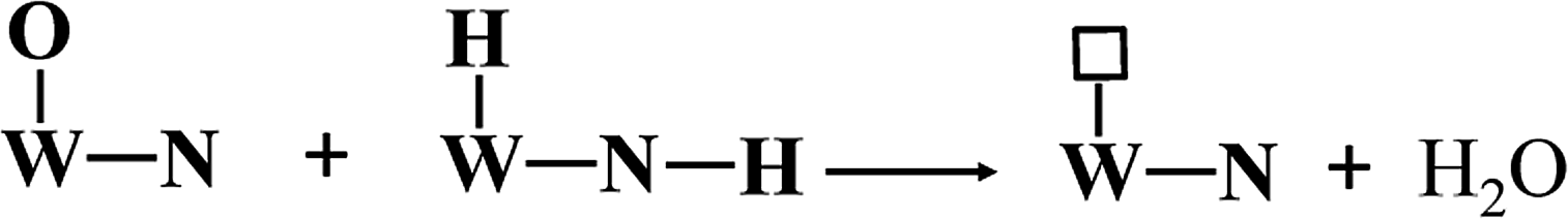
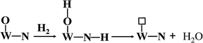
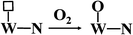
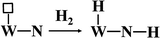
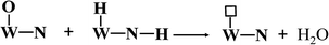
Apparently, WN prepared at high temperatures has high concentration of nitrogen-deficient W atoms on the surface, which can be easily filled by oxygen to form W–O bonds. In our actual case, the oxygen gas begins to evolve at the state-of-charge of 80% at the positive electrode together with 21% oxygen gas of the air in the battery, due to which the environment in the battery is always full of oxygen gas. Hydroxy radicals (OH) and water molecules (H2O) were detected in TPD-MS analysis (ESI, Fig. S4†). Referring to the mechanism of hydrogen adsorption and activation by metal carbides and nitrides as proposed by E. Furimsky,15 the hydrogen and oxygen recombination in the nickel–iron battery can be depicted as follows. Hydrogen is activated by O–W–N to form an intermediate and then, it is transferred to H2O; simultaneously, the nitrogen-deficient patch of W (represented by □) is present on the surface (eqn (3)). Then, tungsten oxynitrides are formed immediately due to the oxygen-enriched atmosphere (eqn (4)). Meanwhile, the hydrogen gas generated can be activated and this involves heterolytic dissociation on W–N pairs (eqn (5)). The hydrogen and oxygen radical-like species on the surface of WN particles may be transferred from the surface to H2O molecules (eqn (6)). Hydrogen activation and reaction may be carried out through eqn (3) simultaneously.
| |
 | (3) |
| |
 | (4) |
| |
 | (5) |
| |
 | (6) |
The migration of hydridic hydrogen from the surface to the sub-surface layer and/or interstices may also occur. Sub-surface is the predominant location of the nitrogen atoms in the crystal. The much higher strength of the N–H bond than that of the W–H bond provides the driving force for this process.15 This correctly explains the interesting phenomenon in Fig. 3f; from this figure, we can see that the regularity of the pressure for the first formation cycle is different from that for the second and third cycles. In the second and third cycles, the pressure increase and decrease is related to the charge and discharge processes strictly, but this regularity does not occur for the first cycle. The pressure begins to decline at less than half of the charge process and decreases to −15 kPa by the end of the first cycle; this interesting phenomenon is not observed for the battery without the catalyst (Fig. 3e). When hydrogen gas is generated rapidly, majority of the hydridic hydrogen species migrate from the surface to the sub-surface layer and interstices until the equilibrium saturation of the sub-surface is attained (migration is an irreversible process). The hydroxy radical (OH) and water molecule (H2O) detected at high temperatures (noted as II) in the TPD-MS analysis are the products of the desorbed hydrogen from sub-surface reacting with oxygen (ESI, Fig. S4†). Simultaneously, because the oxygen in the battery participates in recombination with hydrogen on the surface of WN/NC, the pressure of the battery decreases to a negative value. After that, only recombination is carried out on the surface of the particles and the related regularity is observed in other cycles.
The average catalytic velocity (![[small nu, Greek, macron]](https://www.rsc.org/images/entities/i_char_e0ce.gif) ) of WN/NC for hydrogen and oxygen recombination at room temperature in the nickel–iron battery can be calculated by the declined pressure of the battery (ΔP) in unit time (Δt) of the kinetics curve of the hydrogen and oxygen recombination in the discharge process (Fig. 3d) and is shown as formula (7).
) of WN/NC for hydrogen and oxygen recombination at room temperature in the nickel–iron battery can be calculated by the declined pressure of the battery (ΔP) in unit time (Δt) of the kinetics curve of the hydrogen and oxygen recombination in the discharge process (Fig. 3d) and is shown as formula (7).
| | |
= ΔP/Δt
| (7) |
| | |
′ = V/RTm
| (9) |
Combined with the ideal-gas equation (formula (8)), the average catalytic velocity ′ (mol h−1 gcat−1) can be written as formula (9). V represents the gas volume of the battery (7 ml), R is the ideal gas constant (8.314 J mol−1 K−1), T represents the absolute temperature (303 K) and m is the mass of the WN catalyst used in the battery (39 mg); thus, the calculated average catalytic velocity (′) is 140 μmol h−1 gcat−1. As for the stability and catalytic life of the WN/NC catalyst, we can see from Fig. 3b that the test is carried out incessantly for 954660 s, and the pressure of the battery is kept stable, illustrating that the catalytic performance of WN/NC catalyst does not decay. This proves the stability and long life of WN/NC particles.
4. Conclusion
In summary, nanoscale WN/NC particles were synthesized through a facile route and presented efficient catalytic performance for hydrogen and oxygen recombination at room temperature with an average catalytic velocity of 140 μmol h−1 gcat−1 and long catalytic life of 954660 s without decay in the catalytic performance. This allowed the nickel–iron battery to be sealed and maintenance-free, and it also exhibited low cost; thus, the nickel–iron battery can be used for large-scale energy storage systems.
Conflicts of interest
There are no conflicts to declare.
Acknowledgements
The research was supported by provincial support project of Sichuan, China (Grants No. 0060305301007)
Notes and references
- J. B. Goodenough and Y. Kim, Chem. Mater., 2010, 22, 587 CrossRef CAS.
- B. Scrosati, J. Hassoun and Y. K. Sun, Energy Environ. Sci., 2011, 4, 3287 RSC.
- J. O. G. Posada, A. J. R. Rennie, S. P. Villar, V. L. Martins, J. Marinaccio and A. Barnes, Renewable Sustainable Energy Rev., 2017, 68, 1174 CrossRef CAS.
- A. K. Shukla, S. Venugopalan and B. Hariprakash, J. Power Sources, 2001, 100, 12 CrossRef.
- A. K. Manohar, S. Malkhandi, B. Yang, C. Yang, G. K. Surya Prakash and S. R. Narayanan, J. Electrochem. Soc., 2012, 159, A1209 CrossRef CAS.
- A. S. Rajan, S. Sampath and A. K. Shukla, Energy Environ. Sci., 2014, 7, 1110 RSC.
- B. Yang, S. Malkhandi, A. K. Manohar, G. K. Surya Prakash and S. R. Narayanan, Energy Environ. Sci., 2014, 7, 2753 RSC.
- B. Hariprakash, S. K. Martha, M. S. Hegde and A. K. Shukla, J. Appl. Electrochem., 2005, 35, 27 CrossRef CAS.
- R. B. Levy and M. Boudart, Science, 1973, 181, 547 CrossRef CAS PubMed.
- M. Saito and R. B. Anderson, J. Catal., 1980, 63, 438 CrossRef CAS.
- J. B. Claridge, A. P. E. York, A. J. Brungs, C. Marquez-Alvarez, J. Sloan and S. C. Tsang, J. Catal., 1998, 180, 85 CrossRef CAS.
- M. K. Neylon, S. Choi, H. Kwon, K. E. Curry and L. T. Thompson, Appl. Catal., A, 1999, 183, 253 CrossRef CAS.
- Y. Wang, W. Li, M. Zhang, N. Guan and K. Tao, Appl. Catal., A, 2001, 215, 39 CrossRef CAS.
- R. Kojima and K. I. Aika, Appl. Catal., A, 2001, 218, 121 CrossRef CAS.
- E. Furimsky, Appl. Catal., A, 2003, 240, 1 CrossRef CAS.
- C. Shi, X. F Yang, A. M. Zhu and C. T. Au, Catal. Today, 2004, 93, 819 CrossRef.
- H. B. Wu, B. Y. Xia, L. Yu, X. Y. Yu and X. W. Lou, Nat. Commun., 2015, 6, 1 Search PubMed.
- C. Liang, L. Ding, C. Li, M. Pang, D. Su and W. Li, Energy Environ. Sci., 2010, 3, 1121 RSC.
- D. R. Stellwagen and J. H. Bitter, Green Chem., 2015, 17, 582 RSC.
- R. W. Gosselink, D. R. Stellwagen and J. H. Bitter, Angew. Chem., Int. Ed., 2013, 52, 5089 CrossRef CAS PubMed.
- W. Zheng, T. P. Cotter, P. Kaghazchi, T. Jacob, B. Frank and K. Schlichte, J. Am. Chem. Soc., 2013, 135, 3458 CrossRef CAS PubMed.
- S. Ababou-Girard, H. Sabbah, B. Fahre, K. Zellama, F. Solal and C. Godet, J. Phys. Chem. C, 2007, 111, 3099 CrossRef CAS.
- Y. W. Yang, J. B. Wu, J. Wang, Y. F. Lin and H. T. Chiu, Surf. Sci., 2006, 600, 743 CrossRef CAS.
- M. Shi, P. Yang, L. Huang, H. Chen and X. Mao, Electrochim. Acta, 2017, 238, 210 CrossRef CAS.
Footnote |
| † Electronic supplementary information (ESI) available. See DOI: 10.1039/c8ra06437g |
|
| This journal is © The Royal Society of Chemistry 2018 |
Click here to see how this site uses Cookies. View our privacy policy here. 
 Open Access Article
 This Open Access Article is licensed under a Creative Commons Attribution-Non Commercial 3.0 Unported Licence
 *ab
*ab