 Open Access Article
Recovery and purification of ionic liquids from solutions: a review
Jingjing Zhou
ab,
Hong Sui
abc,
Zhidan Jia
ab,
Ziqi Yang
ab,
Lin He
 *abc and
Xingang Li
abc
aSchool of Chemical Engineering and Technology, Tianjin University, 300072 Tianjin, China. E-mail: linhe@tju.edu.cn; Tel: +86-022-27404701
bNational Engineering Research Center of Distillation Technology, 300072 Tianjin, China
cCollaborative Innovation Center of Chemical Science and Engineering, 300072 Tianjin, China
First published on 21st September 2018
Abstract
With low melting point, extremely low vapor pressure and non-flammability, ionic liquids have been attracting much attention from academic and industrial fields. Great efforts have been made to facilitate their applications in catalytic processes, extraction, desulfurization, gas separation, hydrogenation, electronic manufacturing, etc. To reduce the cost and environmental effects, different technologies have been proposed to recover the ionic liquids from different solutions after their application. This review is mainly focused on the recent advances of the recovery and purification of ionic liquids from solutions. Several methods for recovery of ionic liquids including distillation, extraction, adsorption, membrane separation, aqueous two-phase extraction, crystallization and external force field separation, are introduced and discussed systematically. Some industrial applications of ionic liquid recovery and purification methods are selected for discussion. Additionally, considerations on the combined design of different methods and process optimization have also been touched on to provide potential insights for future development of ionic liquid recovery and purification.
1. Introduction
Ionic liquids (ILs) are a class of molten salts with melting points below 100 °C. Generally, this kind of chemical is composed of organic cations and organic/inorganic anions. The cations are mainly, but not limited to alkylated imidazole, pyrrole or pyridine derivatives, quaternized alkyl amines and alkyl phosphines (Table 1), etc. Some representative anions of ionic liquids are halides, alkyl sulfates, fluorinated hydrocarbons, carboxylic acids and amino acids,1–3 as shown in Table 2. In addition to the two most common IL types, i.e., protic and aprotic ILs,4 some other ILs subclasses have also been reported, including polymeric ILs,5 double salt ILs,6 dicationic ILs,7 deep eutectic solvent,8 chiral ILs,9 solvate ILs,10 etc. Some ionic liquids mentioned in the review are listed in Table 3. During the past decades, ILs have attracted much attention from researchers and engineers due to their unique characteristics such as negligible vapour pressure, non-flammability, high thermal stability and a wide electrochemical (conductivity) window. In addition, the physical and chemical properties (e.g., solubility, polarity, viscosity and acidity) of ILs are also found to be able to be designed by combination and modification of their cations and anions. In this way, the ILs have been applied in certain processes, such as catalytic reactions,11,12 separations,13,14 desulfurization,15,16 hydrogenation,17,18 and electrochemistry.19,20| Acronym | Name | Structure | Reference |
|---|---|---|---|
| [Hmim]+ | 1-Methylimidazolium |  |
43 |
| [Mmim]+ | 1,3-Dimethylimidazolium |  |
30 |
| [C2mim]+ | 1-Ethyl-3-methylimidazolium |  |
44 |
| [Amim]+ | 1-Allyl-3-methylimidazolium |  |
45 |
| [C4mim]+ | 1-Butyl-3-methylimidazolium |  |
46 |
| [C6mim]+ | 1-Hexyl-3-methylimidazolium |  |
47 |
| [C8mim]+ | 1-Octyl-3-methylimidazolium |  |
48 |
| [C16mim]+ | 1-Hexadecyl-3-methylimidazolium |  |
49 |
| [PDmim]+ | 1-Propyl-2,3-dimethylimidazolium |  |
50 |
| [(CH2)nCOOHmim]+ | 1-Alkylcarboxylic acid-3-methylimidazolium |  |
51 |
| [C4(mim)2]+ | 1,1-Bis(3-dimethylimidazolium-1-yl)butane |  |
52 |
| [C4-py]+ | 1-Butylpyridinium |  |
53 |
| [C6-py]+ | 1-Hexylpyridinium |  |
54 |
| [C8-py]+ | 1-Octylpyridinium |  |
55 |
| [C4-3-mpy]+ | 1-Butyl-3-methylpyridinium |  |
56 |
| [C4-4-mpy]+ | 1-Butyl-4-methylpyridinium |  |
47 |
| [Bmpyr]+ | 1-Butyl-1-methylpyrrolidinium |  |
54 |
| [Hmpyr]+ | 1-Hexyl-1-methylpyrrolidinium |  |
57 |
| [DBNH]+ | 1,5-Diazabicyclo[4.3.0]non-5-enium |  |
58 |
| [DBU-Bu]+ | 8-Butyl-1,8-diazabicyclo[5.4.0]undec-7-ene |  |
59 |
| [HSO3-bCPL]+ | 1-(4-Sulfonic group) butylcaprolactamium |  |
60 |
| [HBth]+ | Benzothiazolium |  |
61 |
| [N4444]+ | Tetrabutylammonium |  |
62 |
| [N1,1,1,12]+ | Dodecyltrimethylammonium |  |
59 |
| [P4444]+ | Tetrabutylphosphonium |  |
63 |
| [TMGH]+ | 1,1,3,3-Tetramethylguanidinium |  |
64 |
| Acronym | Name | Structure | Reference |
|---|---|---|---|
| [Cl]− | Chloride |  |
|
| [Br]− | Bromide |  |
|
| [I]− | Iodine |  |
|
| [BF4]− | Tetrafluoroborate |  |
46 |
| [PF6]− | Hexafluorophosphate |  |
65 |
| [MS]− | Methylsulfate |  |
46 |
| [TfO]− | Trifluoromethanesulfonate |  |
46 |
| [Tf2N]− | Bis(trifluoromethylsulfonyl)imide |  |
57 |
| [BETI]− | Bis(perfluoroethanesulfonyl)imide |  |
66 |
| [Ace]− | Acesulfamate |  |
67 |
| [O2CH]− | Formate |  |
68 |
| [Ac]− | Acetate |  |
69 |
| [CO2Et]− | Propionate |  |
64 |
| [TFA]− | Trifluoroacetate |  |
70 |
| [NO2]− | Nitrite |  |
71 |
| [SO4]2− | Sulfate |  |
71 |
| [HSO4]− | Hydrogen sulfate |  |
60 |
| [DMP]− | Dimethylphosphate |  |
72 |
| [Tf-Leu]− | N-Trifluoromethanesulfonyl leucine |  |
63 |
| [TOS]− | Tosylate |  |
73 |
| [FeCl4]− | Tetrachloroferrate |  |
33 |
| [FeBrCl3]− | Bromotrichloroferrate |  |
59 |
| Acronym | Name | Structure | Reference |
|---|---|---|---|
| DIMCARB | N′,N′-Dimethylcarbamate |  |
74 |
| CYPHOS IL 101 | Tetradecyl(trihexyl)phosphonium chloride |  |
75 |
| CYPHOS IL 104 | Trihexyl(tetradecyl)phosphonium bis-2,4,4-(trimethylpentyl)phosphinate | 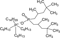 |
76 |
| ECOENG500 | PEG-5 cocomonium methylsulfate |  |
75 |
| CTMA | Trioctylmethyl ammonium camphorate |  |
77 |
However, ILs are, at least, partially miscible with water or hydrocarbons, which will inevitably end up in the aqueous or non-aqueous environment through industrial waste stream.21,22 Although there are multiple ILs created from GRAS (Generally Recognized As Safe) list ions,23,24 the leaking of some ILs with certain toxicity may cause potential environmental impact.25 On the other hand, a major concern associated with adopting ILs in large scale industrial processes is their relatively high cost in comparison with conventional solvents. The expense can be offset to some extent if ILs are recycled.26 Therefore, efficient separation and recovery of ILs from different solutions are essential for their ecological and economic applications.
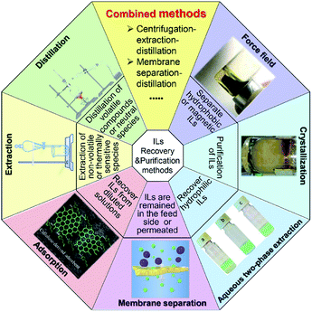
During the past decades, great attempts have been made by researchers for the recovery and recycling of ILs, including distillation,27 extraction,28 adsorption,29 membrane separation,30 aqueous two-phase extraction,31 crystallization32 and force field separation,33 etc., shown in Fig. 1. Among these methods, distillation and extraction are two of the most commonly used ways. Distillation, especially vacuum distillation, is usually employed as the final step for separation of volatile products from ILs. When it comes to non-volatile or thermally sensitive substances, extraction is a more preferable choice. Adsorption is considered to be a robust and non-destructive way to recover ILs from aqueous solution. Nonetheless, the desorption of the adsorbed ILs still has a long way. Membrane technology is also employed to separate ILs, where ILs could be remained in the feed side or permeate through the membrane. The aqueous two-phase system, where there is no use of traditional volatile organic solvents in the whole process, is usually applied for recovering hydrophilic ILs. Other technologies such as crystallization and force field separation have also been developed to obtain ionic liquids with high purity or save much energy.
There are some comprehensive reviews on the synthesis and application of ionic liquids.34–42 In this review, the recent advances regarding the methods used for the recovery and recycling of ILs, either single or combination of these methods have been reviewed and discussed. We hope this review could provide some basic information and strategy for researchers and engineers in choosing and designing suitable recovery methods in practice.
2. Methods for recovery and purification of ionic liquids from solutions
2.1. Distillation
Distillation is the most commonly used process for separating liquid mixtures through gradient boiling and condensation based on the differences in the volatility of the components in the mixture. Due to simple operation, the distillation has been widely applied for the recovery of ILs. During the process, according to the types of the distillates, the distillation could be operated in three ways. One is the distillation of volatile species while leaving the ionic liquids in the distillation equipment. Another way is distillation through the reaction of ILs, where ILs form distillable carbene or decompose into distillable neutral compounds. The third way is that ILs are distilled out as intact ion pairs.Conventional distillation methods. Separation of ILs and low boiling point compounds by conventional distillation could be achieved in a rotary evaporator27,57,58,78–81 or a thin film evaporator.82–85 The rotary evaporator works on the basis of reducing the pressure above a bulk liquid thus lowering the boiling points of components in the liquid mixture. Compared to the standard organic distillation glassware, the heating surface in rotary evaporator is enlarged due to the formation of a thin film of warm solvent, which is caused by the centrifugal force and the frictional force between the wall of the rotating flask and the liquid sample. Therefore, the rotary evaporator is a commonly used device in laboratories to distillate out high boiling and/or air sensitive compounds. Dennewald et al.57 applied the rotary evaporator to recover the 1-hexyl-1-methylpyrrolidinium bis(trifluoromethylsulfonyl)imide ([Hmpyr][Tf2N]) from solutions. This kind of ionic liquid was used as solvent in biotransformation of 2-octanone into (R)-2-octanol, where the IL formed emulsions with the aqueous phase containing biocatalyst due to their immiscibility. Therefore, before the distillation, the emulsions should be pretreated for complete separation by centrifugation. After the pretreatment, the IL phase was introduced in a rotary evaporator for distillation under the minimal pressure (P < 5 mbar) at 130 °C for 5 h. The product ((R)-2-octanol) and nonconverted 2-octanone were distilled out and IL was remained as residue. After using the ILs for 25 cycles, they obtained an average recovery of [Hmpyr][Tf2N] at about 82.78 ± 0.83%. Parviainen et al.58 evaluated the recyclability of 1,5-diazabicyclo[4.3.0]non-5-enium acetate ([DBNH][Ac]) that was used as a dissolution solvent for cellulose. The rotary evaporator (1–3 mbar) was applied to remove traces of water from the [DBNH][Ac] at 60 °C for 2 h. The IL could be recycled from aqueous media with an average recovery rate of 95.6 wt%. However, they proposed that the residence time for this kind of batch distillation apparatus was very long, thus leading to the significant hydrolysis of ILs. In addition, these hydrolysis products would deteriorate the cellulose dissolution capability of ILs.
Different from the rotary evaporator, the thin film evaporator could be operated continuously and applied at pilot scale. During the thin film evaporation, the liquid mixture flows downwards the evaporator wall by gravity or assisted by mechanical wipers, forming a continuous thin film that covers the evaporator surface. One of the advantages of the falling film evaporator is the high heat transfer coefficients and short residence time of the liquid, making it ideal to separate heat-sensitive, viscous or low thermal conductivity substances.86 Ahmad et al.85 tested the feasibility of a thin film evaporator in recovering [DBNH][Ac] from a solution containing 80 wt% water at pilot scale. The detailed diagram of the evaporation system is shown in Fig. 2. The IL solution was pumped from the vessel through the preheater and fed to the top of the evaporator. The feed was distributed around the evaporator walls under centrifugation force by the wiper system. The IL rich residue was collected at the bottom of evaporator while the vapor product with the high proportion of water was collected at the top as distillate. The operational parameters, such as feed flow rate, operation pressure and evaporator jacket temperature have been systematically investigated. The flow rate was observed to exert slight effect on the product composition, while the separation efficiency increased with higher jacket temperature and lower pressure. It was found that the [DBNH][Ac] product with low water contents (5–11.7 wt%) was obtained.
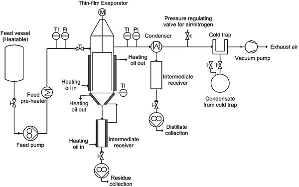 | ||
| Fig. 2 Flow sheet of the agitated thin-film evaporation system. (TI) Temperature indicator; (FI) flow indicator; (PI) pressure indicator. Reproduced with permission from ref. 85. Copyright 2016 Elsevier Ltd. | ||
The conventional distillation technology has been employed for industrial application. A process of the chlorination of butanediol with gaseous HCl was developed by BASF (Germany), where the ionic liquid acts as solvent.87 After the reaction, the upper organic phase which was consisted of the reaction product (1,4-dichlorobutane) was easily separated from the lower IL phase. The water that was formed as by-product could be distilled off from the IL phase (not explicitly mentioned). Thus the IL could be used for the next run without any further processing. BASF has also run an extractive distillation process in a pilot plant.73,88 The 1-ethyl-3-methylimidazolium tosylate ([C2mim][TOS]) was used as an entrainer for the separation of azeotropic mixtures (methanol–trimethylborate (MeOH–TMB)). Fig. 3 shows a flow sheet of the extraction distillation process involving the recovery of IL by thin film evaporation. The TMB was distilled and obtained at the top of the column. The MeOH was drawn at the bottom. The mixture of IL and residual MeOH was removed to a falling film evaporator, where the MeOH was distilled and the recovered IL was fed at the top of the extraction column and reused. The [C2mim][TOS] showed stable performance for the separation of MeOH–TMB during a period of 3 months.
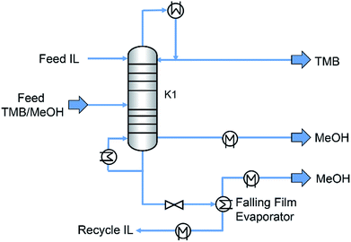 | ||
| Fig. 3 Flow sheet of extraction distillation process involving the recovery of IL by thin film evaporation. Reproduced with permission from ref. 73. Copyright 2005 Wiley-VCH. | ||
Microwave-assisted distillation. Microwaves are electromagnetic waves with radio frequencies in the range from 300 MHz to 300 GHz (wavelengths from 1.0 mm to 1.0 m). Compared with the traditional heating, the microwave irradiation could be used to heat the materials to high temperature in a fast way through excitation of polar molecules (via dipole rotation) or ions (via ionic conduction) in the microwave field.89,90 Due to this property, the microwave irradiation has been widely applied in many processes such as organic synthesis,91 biomass pretreatment,92 extraction93 and evaporation,94 etc. Ha et al.46 investigated the microwave-assisted distillation for separation of three hydrophilic ILs (1-butyl-3-methylimidazolium tetrafluoroborate ([C4mim][BF4]), 1-butyl-3-methylimidazolium trifluoromethanesulfonate ([C4mim][TfO]) and 1-ethyl-3-methylimidazolium methylsulfate ([C2mim][MS])) and two hydrophobic ILs ([C4mim][PF6] and [C4mim][Tf2N]) from ILs/water mixture. It was found that for the homogeneous mixture of hydrophilic ILs and water (1
![[thin space (1/6-em)]](https://www.rsc.org/images/entities/char_2009.gif) :
:![[thin space (1/6-em)]](https://www.rsc.org/images/entities/char_2009.gif) 1, w/w), the energy efficiency was at least 52 times higher than those in conventional vacuum distillation. However, for the oil–water dual phases, although the water content in hydrophobic ILs was less than that in hydrophilic ILs, much more energy was observed to be required to distill the water from the water-saturated hydrophobic ILs. Unfortunately, the detailed mechanisms for this phenomenon are still not clear.
1, w/w), the energy efficiency was at least 52 times higher than those in conventional vacuum distillation. However, for the oil–water dual phases, although the water content in hydrophobic ILs was less than that in hydrophilic ILs, much more energy was observed to be required to distill the water from the water-saturated hydrophobic ILs. Unfortunately, the detailed mechanisms for this phenomenon are still not clear.
Molecular distillation. Molecular distillation, a type of short-path vacuum distillation, has been used for the separation of heat-sensitive materials based on the differences in the mean free path of gas molecules.95 This method is characterized by a short-term exposure of the distilled liquid at elevated and high vacuum in the distillation column, and a short distance (20–50 mm) for vapor from the evaporator to reach the condenser.96 Blahušiak et al.76 employed molecular distillation for regeneration of butanoic acid from a hydrophobic phosphonium IL (commercial name CYPHOS IL 104). The IL was diluted with dodecane to decrease its viscosity. Results showed that 88% of the butanoic acid and almost 90% of dodecane was distillated out. Huang et al.45 applied molecular distillation to recover 1-allyl-3-methylimidazolium chloride ([Amim][Cl]) used in a homogenous cellulose acetylation system. Their results showed that the volatile impurities were distilled while the [Amim][Cl] remained as a residue which was recycled and reused for 5 times without any change in the structure.
Distillation by formation of carbene. For some imidazolium-based ILs, the neutral carbene molecules could be formed by deprotonation of the cations of ILs in the presence of base at heating (Fig. 4a).97–99 The carbene could be distilled out and reacted with protic acid to re-form the ILs, thus allowing the recovery or purification of ILs. Maase et al.99 reported a process in which 1,3-substituted imidazolium salt could be purified. In this process, the IL prepared by a conventional route was heated with the addition of a strong base (e.g., alkoxide) under reduced pressure. Then the corresponding carbene, 1,3-substituted imidazol-2-ylidene, was formed and distilled off. Since the anions of ILs were not distilled and remained as residual, the condensed carbene was subsequently reacted with the fresh protic acid which contained the anions of ILs to be purified. Consequently, the purified 1,3-substituted imidazolium salt was re-formed. However, in this method, the distillable carbene need to be re-reacted with the protic acid in molar stoichiometry, which would increase the operational difficulty and the cost of the process compared to simple distillation of volatile compounds.
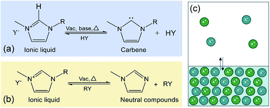 | ||
| Fig. 4 Distillation of ILs as: (a) carbenes;97 (b) neutral compounds;88 (c) intact ion pairs, reproduced with permission from ref. 109. Copyright 2006 Nature Publishing Group. | ||
Distillation by decomposition reaction. When being heated, the ILs would decompose into uncharged distillable compounds via protonation or alkylation of the anions at elevated temperature under vacuum (Fig. 4b).44,100,101 These neutral decomposition compounds could be distilled out and re-reacted to IL. Take the recycling of 1-methyl-3-ethylimidazolium chloride ([C2mim][Cl]) from contaminants (not pointed out by the author) as example,44 when the [C2mim][Cl] was heated at a temperature ranging from 200 °C to 300 °C under reduced pressure, the IL would be partially decomposed to give 1-methylimidizole, 1-ethylimidizole, chloromethane and chloroethane. These neutral imidazole and alkylated agents could be distilled, followed by being collected and reacted to produce a mixture of 1,3-dimethylimidazolium chloride, 1,3-diethylimidazolium chloride and [C2mim][Cl]. However, this process is based on the decomposition of ILs and often not controlled, thus the pure ILs are difficult to be obtained. Recently, some acid–base conjugate ILs (e.g. 1,1,3,3-tetramethylguanidinium propionate ([TMGH][CO2Et])64 and 1,5-diazabicyclo[4.3.0]non-5-enium propionate ([DBNH][CO2Et])102) were synthesized for efficient biomass treatment. It is found that their distillable characteristic is attributed to the higher acidity of the cations, allowing for the dissociation of ILs to the neutral acid and base IL precursors at elevated temperatures. For example, when being heated at 100–200 °C under reduced pressure (1 mmHg), the [TMGH][CO2Et] was dissociated into the 1,1,3,3-tetramethylguanidine (TMG) and carboxylate (HCO2Et), which could be vaporized and reacted to re-form the [TMGH][CO2Et].64
In addition to the above ILs going through deprotonation of the cations or alkylation of the anions during distillation, a series of distillable amide-derived aprotic ILs were also synthetized.103–105 The amide O-alkylation reaction is readily reversible varying with temperature. The volatile molecular precursors were found to be vacuum distilled and reverted to ILs at room temperature.103 Furthermore, the distillable ILs from the family of alkyl carbamate salts have also been reported.74,106–108 Separation of these ILs can be achieved at moderate temperatures due to the release of the neutral species (CO2 and the dialkylamine) when being heated. The reformation of the ILs could be realized by subsequent recombination of the two compounds when cooling. For instance, during the aldol-condensation reactions, the N′,N′-dimethylcarbamate (DIMCARB) was used as the medium. This kind of ionic liquid would be dissociated to dialkylamine and CO2 under high vacuum and relatively low temperature (60–105 °C). These dissociated components could be re-associated by condensation.74
2.2. Extraction
Liquid–liquid extraction is a separation method based on the difference in solubility of the separated components in two immiscible liquid phases. It has been proved to be an efficient method for recovering ILs. Different solvents such as water, organic solvents and supercritical carbon dioxide (scCO2) have been employed during the extraction processes.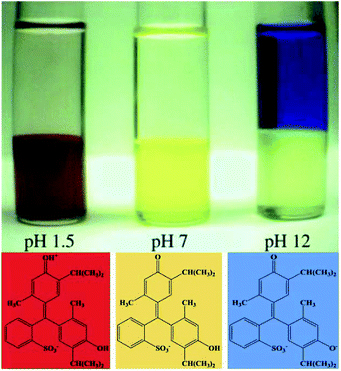 | ||
| Fig. 5 The phase preference of the three forms of thymol blue in [C4mim][PF6] at different pH. Reproduced with permission from ref. 110. Copyright 2000 The Royal Society of Chemistry. | ||
Additionally, the acid aqueous solution could also be used to separate metal complexes from IL after using IL for extraction of metal ions from aqueous solutions. Generally, traces of metal ions could be extracted from aqueous phase into the IL phase in the form of metal complexes by adding metal chelator. The metal complexes in IL phase would be dissociated when the acid solution is added to decrease the pH value, allowing metal ions to be separated from IL. Wei et al.111 utilized [C4mim][PF6] to extract Pb2+ (20 ppm) from aqueous solution at pH 6.5, where a metal chelator (dithizone) was employed as extractant to form neutral metal–dithizone complexes. The complexes were then stripped from IL through mixing with 0.1 M HNO3 solution. The average extraction efficiency of Pb2+ was up to 98.4 ± 0.2%. Recently, a task-specific ILs with carboxyl-functional group have been proposed for the extraction of metal ions from aqueous phase. In the work of Chen et al.,51 the carboxyl-functionalized imidazolium ILs (1-alkylcarboxylic acid-3-methylimidazolium bis(trifluoromethanesulfonyl)imide ([(CH2)nCOOHmim][Tf2N] (n = 3, 5, 7))) were employed as extractants and four imidazolium-based ILs ([Cnmim][Tf2N] (n = 4, 6, 8, 10)) were used as diluents to extract Sc3+ from aqueous solution at 30 °C. A cation exchange mechanism was proposed for the extraction process that when one mole of metal ion migrated to the IL phase, two moles protons of extractant and one mole cations of the diluent were transferred to aqueous phase simulataneously, which could be described by eqn (1):
| Sc3+ + 2[(CH2)7COOHmim][Tf2N] + [C4mim][Tf2N] = Sc[(CH2)7COOmim]2[Tf2N]3 + 2H+ + [C4mim]+ | (1) |
In addition to extracting the hydrophobic compounds, ILs would also be extracted out as solutes. For instance, the mixture of alkali lignin (200 mg) and 1-ethyl-3-methylimidazolium acetate ([C2mim][Ac]) (2 mL) could be separated by adding a specific amount of selected solvents (isopropanol, ethanol, acetonitrile, allyl alcohol, methanol) (5–100 mL) at room temperature.69 The IL was extracted into the solvent phase under stirring, while the lignin pulp was precipitated after centrifugation. The four solvents were all able to extract IL thoroughly. However, some lignin was still present in the solvent phase. The isopropanol proved to be the most effective solvent, allowing the lowest amount of lignin in the supernatant liquid (13 wt% when 100 mL solvent was added), followed by ethanol and acetonitrile (25–27 wt%). Relatively high amounts of lignin being about 54 and 67 wt% were provided by allyl alcohol and methanol, respectively.
The method of organic solvent extraction has been applied in industry for IL recovery. The Central Glass Company (Japan) has developed and commercialised a Sonogashira coupling reaction using a tetraalkylphosphonium ionic liquid as the solvent.39 The aryl halide (3,5-bis(trifluoromethyl)bromobenzen) was reacted with a terminal alkyl-alkyne (1,1-dimethyl-2-propyn-1-ol) catalysed by palladium–copper. After the reaction, the product was separated by extraction with hexane, and the by-product salt ([HNEt3][Br]) was removed with a counter-current flow of water. The remaining ionic liquid-catalyst solution could be recycled several times with little loss of the catalytic activity. However, the environmental impact maybe come up with the utilizing of organic solvent. Therefore, employing more environmentally friendly solvents as replacements has become one of the attractive directions.
The application of scCO2 as extraction solvent for separation of IL and solute was based on three aspects: (i) the CO2 can be easily dissolved in the IL phase. This is not only favorable for the contact of CO2 with the desired solute, but also decreases the viscosity of the ILs.122 (ii) The dissolved CO2 in the IL phase can be completely removed by depressurization, thus pure IL is able to be remained after extraction. (iii) Since most of ILs are not appreciably solubilized in the CO2 phase, the problem of interactive contamination of the gas phase is eliminated as well.123
The scCO2 was firstly introduced by Blanchard et al.28 for the quantitative extraction of non-volatile organic compounds, naphthalene, from [C4mim][PF6]. It was reported that 94–96% of naphthalene was separated with CO2 at 13.8 MPa and 40 °C. Subsequently, a variety of other organic solutes (aromatic and aliphatic) were reported to be extracted from [C4mim][PF6] by using the scCO2 with recovery over 95%.123 However, it was found that the [C4mim][PF6] could be dramatically dissolved in scCO2 when polar organic compounds (e.g., ethanol and acetone) were extracted into the scCO2 phase, especially when the concentration of these polar solutes in scCO2 exceeded 10 mol%.124 This finding presented a challenge when trying to remove high concentration polar organics from ILs. More recently, the separation of metal ions from ILs by employing scCO2 125 or modified scCO2![[thin space (1/6-em)]](https://www.rsc.org/images/entities/char_2009.gif) 126,127 has been explored. Mekki et al.125 proved that the stripping of metal complexes of lanthanides (La3+ and Eu3+) from 1-butyl-3-methylimidazolium bis[(trifluoromethyl)sulfonyl]imide ([C4mim][Tf2N]) could be achieved by scCO2 coordinated with β-diketone extractants.
126,127 has been explored. Mekki et al.125 proved that the stripping of metal complexes of lanthanides (La3+ and Eu3+) from 1-butyl-3-methylimidazolium bis[(trifluoromethyl)sulfonyl]imide ([C4mim][Tf2N]) could be achieved by scCO2 coordinated with β-diketone extractants.
In addition to the extraction with scCO2, it was also observed by Scurto and coworkers50,128 that the relatively low-pressure CO2 could also be used to separate some hydrophobic and hydrophilic ILs. They found that the solutions of methanol and [C4mim][PF6] could be induced to form three phases in the presence of CO2.128 As illustrated in Fig. 6, the methanol and [C4mim][PF6] were completely miscible at ambient conditions. When a pressure of CO2 was placed upon the mixture, a second liquid phase would appear. If the pressure of CO2 was further increased, the upper liquid layer which was rich in methanol, could merge with the CO2-rich gas phase. Then the newly formed phase was completely free of the ILs. The mechanism for this phenomenon would be ascribed to the expansion of the organic methanol phase by the CO2. This phase expansion decreases the dielectric constant, forcing a significant amount of ILs into a separated liquid phase. Zhang et al.129 complemented that in the [C4mim][PF6]/methanol/CO2 system, increasing the CO2 pressure and decreasing the temperature could enhance the separation of IL from methanol. Scurto et al.50 pointed out the introduction of gaseous or liquid CO2 could be favourable to the separation of both the hydrophobic ([C4mim][PF6] and 1-propyl-2,3-dimethylimidazolium bis(trifluoromethylsulfonylimide) ([PDmim][Tf2N])), and the hydrophilic ([C4mim][BF4] and [C4mim][TfO]) ILs from aqueous solutions. As shown in Fig. 7, at low CO2 pressure, mixture of IL and water presented as one homogeneous phase. As the pressure of CO2 increased, two liquid phases could appear. The lower liquid phase was rich in IL, the middle liquid phase was rich in water while the upper phase was mostly CO2 with a small amount of dissolved water. However, it was difficult to achieve an IL-rich phase with more than 75.63 wt% of IL because this phase still contained water and CO2 even at high pressure of 20 MPa.130
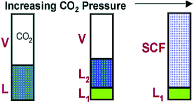 | ||
| Fig. 6 Schematic of [C4mim][PF6]/methanol phase behavior with increasing CO2 pressure. Reproduced with permission from ref. 128. Copyright 2002 American Chemical Society. | ||
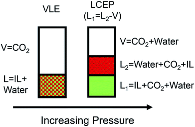 | ||
| Fig. 7 Phase behavior of IL/water/CO2 mixture at increasing pressure at near-ambient temperatures. Reproduced with permission from ref. 50. Copyright 2003 The Royal Society of Chemistry. | ||
2.3. Adsorption
Adsorption has been utilized as a robust and non-destructive method to promote recovery or removal of ILs. Up to date, a variety of adsorbents, such as activated carbons, soils and sediments, ion exchange resins and biosorbents, etc., have been investigated.Effect of ILs structure. The adsorption efficiency is highly dependent on ILs structures, i.e., cation, chain length, and anion of ILs. Palomar et al.70 investigated the separation of a series of 1-butyl-3-methylimidazolium ILs with different anions from aqueous solution using a commercial AC (AC-MkU). The adsorption capacity of adsorbents to ILs varied from 0.1 to 1 mmol g−1, following the order of hydrophobicity of the ILs anions [Tf2N]− > [PF6]− > [TfO]− > [BF4]− > [TFA]− > [Cl]−. Similar result was also obtained by Lemus et al.,48 who examined the adsorption of the 1-alkyl-3-methylimidazolium based ILs at molecular level using COSMO-RS method. Ushiki et al.137 investigated the adsorption of three ILs with different alkyl chain length ([C8mim][Cl], [C6mim][Cl] and [C4mim][Cl]) onto AC. It was observed that when increasing the length of alkyl chains, the adsorption efficiency was also found to be improved, which was consistent with those of Farooq et al.55 and Lemus et al.132 Moreover, with respect to the cation families, uptake of ILs was enhanced in the sequence: ammonium > phosphonium > pyridinium > imidazolium > pyrrolidinium > piperidinium,132 which was in consistent with the content of unsaturated bond in the carbon.134
Effect of properties of ACs. In addition to the chemical structures of ILs, the adsorption of ILs was also highly dependent on the porous structure and surface chemistry of ACs. Lemus et al.48 found that the ACs with micropore and narrow mesopore (with high content of pore lower than 8 nm) presented the highest adsorption capacity for 1-octyl-3-methylimidazolium hexafluorophosphate ([C8mim][PF6]), with the maximum uptake of up to 1 g IL per gram of the adsorbent. Likewise, Jesús136 observed similar result that the adsorption capacity of AC for [C8mim][PF6] was closely related to the available narrow mesopores within the size range from 2 to 8 nm. According to the findings from Farooq et al.'s work,55 it was found that the ILs with length < 1.5 nm and thickness < 0.2 nm (e.g., [C8mim][Cl], [C4mim][Cl] and [[C8-py]][Br]) were preferentially adsorbed in the ultramicropores, and partially adsorbed in the supermicropores and mesopores of ACs. In addition, the adsorption of hydrophilic ILs could be enhanced by introducing oxygenated groups on the ACs surface. Conversely, the hydrophobic ILs were more effectively removed by the thermally treated ACs with lower polarity of surface.55,70
Effect of solution chemistry. Generally, the uptake of imidazolium based ILs could be improved when the pH is increased.55,135 In basic media, the hydroxyl ions tend to be adsorbed at the ACs interface and deprotonate the surface, thus allowing the surface to become negatively charged. Consequently, the adsorption of ILs was facilitated owing to the increase of electrostatic binding sites for IL cations.138 The adsorption of ILs on the ACs is also found to be highly dependent on the salinity of the solution. Neves et al.133 observed that the addition of Na2SO4 salt in solution could improve the adsorption of ILs onto ACs, particularly for the hydrophilic ILs (e.g., [C4mim][Cl] and [C4mim][TfO]) that were poorly removed by ACs. This is because that the formation of salt–ion–hydration complexes reduced the solubility of ILs in water and therefore favoured the partition of ILs onto the ACs.
Effect of ILs structure. Stepnowski et al.47 tested the adsorption of three ILs ([C4mim][Cl], 1-hexyl-3-methylimidazolium chloride ([C6mim][Cl]) and 1-butyl-4-methylpyridinium chloride ([C4-4-mPy][Cl])) onto the selected natural soils. They found that the uptake of ILs by the soil was increased as the increase of the length of the alkyl chain, showing that the hydrophobicity of cation exerts significant influence on the sorption efficiency. This result also suggests that the adsorption of ILs is mainly ascribed to the van der Waals interactions between the nonpolar groups of the IL cations and the organic matter of soils and sediments. This was in accordance with the results obtained by Matzke et al.142 However, the adsorption amounts of ILs on Na-montmorillonite were evidenced to be decreased in the order [C4-py][Br] > [C8-Py][Br] ∼ [Amim][Cl] ∼ [C4mim]Cl > [C8mim][Cl].144 The highest adsorption capacity was obtained for [C4-py][Br] (96 mmol/100 g) and the lowest one for [C8mim][Cl] (72 mmol/100 g). Beaulieu et al.146 found that increasing alkyl chain length did not lead to increased sorption of ILs to four types of aquatic sediments. They postulated this might be due to the fact that hydrophobic interactions were not the dominant adsorption mechanism.
Effect of properties of adsorbents. Physicochemical properties of the soils and sediments such as total organic carbon (TOC), cation exchange capacity (CEC) and clay minerals also play significant roles in the uptake of ILs. Studzinska et al.141 found that the sorption capacity of imidazolium based ILs was positively related to the total organic carbon (TOC) content in soils. Mrozik et al.143 tested the adsorption of nine ILs (imidazolium and pyridinium chlorides) on 11 types of soils. Through chemometric study, it was found that the main soil parameter responsible for the sorption was cation exchange capacity (CEC). Matzke et al.142 investigated the influence of mineral type (kaolinite and smectite) on the cation sorption and desorption behaviors of three imidazolium based ILs ([C4mim][BF4], [C8mim][BF4] and [C4mim][Tf2N]) in a reference soil (Lufa 2.2). They observed that the addition of clays could facilitate the sorption but decrease the desorption for all tested ILs. Particularly, the smectite was found to be stronger than kaolinite in adsorbing ILs. This is because the smectite possesses higher specific surface and higher negative surface charge.
Effect of ILs structure. Influence of the chemical structures of imidazolium based ILs on the adsorption behavior onto ion exchange resins was studied by Li et al.152 It is found that the adsorption of ILs on resins was almost independent on the anions ([Cl]−, [PF6]− and [Tf2N]−) of the ILs. However, increasing the length of alkyl chains was observed to facilitate the adsorption of ILs on the resins. They believed that this adsorption was attributed to the high attractive van der Waals and polar interactions between the ILs and the resins.
Effect of characteristics of resins. Characteristics of resins, such as functional groups, crosslinking degree and ionic form, etc., may influence the adsorption of ILs. Choi et al.153 tested twelve ion exchange resins with different functional groups (i.e., thiourea, iminodiacetic acid, amino phosphonic acid, carboxylic acid and sulfonic acid) in recovering 1-ethyl-3-methylimidazolium acetate ([C2mim][Ac]). During the adsorption process, the cations of ILs were exchanged with the H+ ions and adsorbed onto the resin, while the anions of IL were remained in the aqueous solution without being adsorbed. It was found that the highest uptake (578.2–616.2 mg g−1) of [C2mim] was obtained by sulfonic acid resins (e.g., Amberlite IR120, Dowex HCR-W2, Dowex 50WX8-400, etc.). Similarly, He et al.61 used five ion exchange resins for the recovery of benzothiazolium ILs. The strong acidic ion exchange resin (732(H)) with sulfonic acid showed the highest adsorption capacity of over 310 mg g−1 for all the three tested ILs. What's more, the particle size and crosslinking degree of resins exerted slight influence on the adsorption performance.153 He et al.61 also supplemented that the resin in H+ form possessed greater adsorption capacity than that in Na+ form. The resin with gel type performed better than that of microporous type.
Regeneration and reuse of resins. Regeneration of ion exchange resins is crucial for efficient recovery of the adsorbed ILs and reuse of the resins. Ma et al.154 proposed a two solid-phase recycling method for the recovery of [C4mim][Ac] from Schisandra chinensis fruits extract by macroporous resin (HPD 5000) and ion exchange resin (SK1B). The exhausted ion exchange resin was eluted with 2.0 M HCl followed by 2.0 M NaOH and finally with distilled water, in which way the resin was regenerated and converted to its initial Na+ type. He et al.61 screened different desorbents to improve the desorption performance of ion exchange resin (732) that was loaded with benzothiazolium IL ([HBth][TfO]). It indicated that the 732 resin could be reused for at least three times when using HCl–EtOH–H2O mixture solution (18
![[thin space (1/6-em)]](https://www.rsc.org/images/entities/char_2009.gif) :
:![[thin space (1/6-em)]](https://www.rsc.org/images/entities/char_2009.gif) 8
8![[thin space (1/6-em)]](https://www.rsc.org/images/entities/char_2009.gif) :
:![[thin space (1/6-em)]](https://www.rsc.org/images/entities/char_2009.gif) 74, v/v/v). There was no obvious change in the composition and cation structure of IL after the third recycling. However, there exists a change in the anions of IL during the adsorption–desorption cycle. In other words, during the adsorption, cations are adsorbed onto the resin, but the anions of IL are still remained in the solution. During the subsequent desorption process, the adsorbed cations are exchanged by the Na+ or H+ ions and desorbed into new solution. In this way, another IL that is consisted of original cations and anions of the desorbents is obtained, which presents an inherent drawback of this method.
74, v/v/v). There was no obvious change in the composition and cation structure of IL after the third recycling. However, there exists a change in the anions of IL during the adsorption–desorption cycle. In other words, during the adsorption, cations are adsorbed onto the resin, but the anions of IL are still remained in the solution. During the subsequent desorption process, the adsorbed cations are exchanged by the Na+ or H+ ions and desorbed into new solution. In this way, another IL that is consisted of original cations and anions of the desorbents is obtained, which presents an inherent drawback of this method.
Carbonaceous materials. The carbonaceous function material loaded with carboxylic groups, which was prepared by hydrothermal carbonization of cellulose in the presence of acrylic acid, was used to recover [C4mim][Cl] from aqueous solution.155 In spite of being low surface area of 20 m2 g−1, the prepared carbonaceous microspheres exhibited adsorption capacity (0.171 mmol g−1) comparable to that of commercial ACs with high surface area of 980 m2 g−1 (0.206 mmol g−1). The microspheric particles could be regenerated by HCl aqueous solution for at least 3 times without losing their adsorption capacity. Later, to obtain carbon materials that possess both large surface area and a high number of oxygenated groups, Qi et al.156 synthesized the carbonaceous microsphere materials by chemically modified with KOH to increase the porosity, surface area and oxygen content (Fig. 8). The chemically modified carbonaceous microsphere showed efficient adsorption capacity (0.294 mmol g−1) for hydrophilic IL ([C4mim][Br]) due to the increased polar oxygenated surface groups. Similarly, the zeolite-templated carbon (ZTC) was also synthesized which showed higher adsorption capacity (3.40 mmol g−1) for long alkyl-chained IL, i.e., 1-hexadecyl-3-methylimidazolium chloride ([C16mim][Cl]).49 Zhang et al.29 reported the preparation of an ordered mesoporous carbon (OMC) modified by oxidation with nitric acid. This OMC was used to remove the hydrophilic IL ([C4mim][Cl]) from water. The IL-loaded OMC was regenerated by mixing with 100 mL of 0.01 M HCl solution for 12 h and exhibited stable adsorption behavior within five consecutive adsorption–desorption cycles.
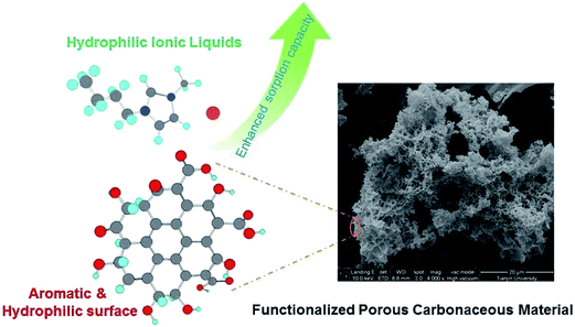 | ||
| Fig. 8 Enhanced sorption of hydrophilic ionic liquids from aqueous solution on functionalized porous carbonaceous material. Reproduced with permission from ref. 156. Copyright 2014 Elsevier Ltd. | ||
Biosorbents. Biosorbents mainly include bacteria, fungi, algae, industrial wastes, agricultural wastes and other polysaccharide materials.157 During the past years, the biochars which are derived from industrial and agricultural wastes have been suggested as potential ILs adsorbents. Shi et al.158 conducted the adsorption of imidazolium-type ILs onto two biochars derived from straw and wood (denoted as SBB and WBB, respectively). The adsorption of ILs on SBB and WBB was found to be pH-dependent and could be promoted by trivalent anions (PO43−). Basically, the biochars could be regenerated using HCl solution. Yu et al.159 produced modified biochars from agricultural wastes, such as peanut shell, corn stalk and wheat straw (denoted as PB-K-N, CB-K-N and WB-K-N) to remove [C4mim][Cl]. Their results showed that the adsorption capacity decreased in the order of PB-KN > CB-K-N > WB-K-N, which was in accordance with the order of total acidic functional groups of these modified biochars. Subsequently, Yu et al.160 compared the adsorption of [C4mim][Cl] on two biochar adsorbents derived from bamboo, i.e., intermediate biochar (BB-K) being pyrolyzed and modified biochar (BB-K-N) being pyrolyzed and oxidized. Among them, the modified biochar (BB-K-N) which had abundant micropores, high specific surface area and oxygen-containing functional groups showed superior adsorption capacity of 0.625 mmol g−1 for [C4mim][Cl], 38.3% higher than that on BB-K. In addition, the bacterial biosorbents have also been investigated for recovery of ILs. Won et al.161 employed five types of bacterial biosorbents for the removal of [C2mim][Ac] from aqueous media. The best result was obtained with Escherichia coli biomass, with a maximum uptake of 72.6 mg g−1 at pH 7 within 10 min. Moreover, more than 91.3% of [C2mim] cations could be readily desorbed from the biosorbent by being contacted with 99.7% pure acetic acid solution.
2.4. Membrane separation
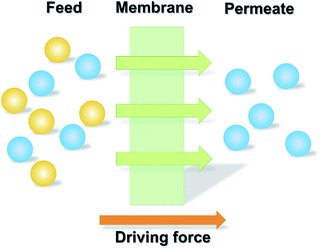
During the past few years, membrane processes have been widely used for the recovery and purification of substances taking advantage of the selective permeability of the membranes (Fig. 9).162,163 For the recovery of ILs, the membrane-based methodology has also been employed owing to its relatively low energy consumption and simple operation.Operation conditions such as the feed concentration and pressure for the nanofiltration process have been investigated. Abels et al.72 used two commercially polyamide (Desal DK and Desal DL) and one polyimide (Starmem 240) membrane to separate saccharides and 1,3-dimethylimidazolium dimethylphosphate ([Mmim][DMP]) of various feed concentrations. The IL was permeated while saccharides were retained by the membranes. However, for all three tested membranes, it was found that a severe decline of permeate flux happened at higher concentrations of IL. This was ascribed to the occurrence of high osmotic pressures, resulting in low permeation of the ILs. Nevertheless, it was feasible to recover IL with purity of 80% by using both polyamide and polyimide membranes. The effect of applied pressure gradient on the rejection of IL (i.e., 1-butyl-3-methylpyridinium tetrafluoroborate ([C4-3-mpy][BF4])) by nanofiltration membrane (NF 270-400) was studied by Hazarika et al.56 The solution flux was found to be increased with the applied pressure. More than 50% rejection of IL was obtained eventually. Similarly, when using two nanofiltration membranes (NF90 and NF27) to concentrate [Amim][Cl], [C4mim][Cl] and [C4mim][BF4] in the IL-H2O system,166 the permeate flux was found to be improved with the increased applied pressure. For the two membranes, the retention of IL was decreased in the order of: [C4mim][Cl] > [C4mim][BF4] > [Amim][Cl], which was inversely proportion to the IL diffusion coefficients in water. The [C4mim][Cl] could be concentrated from its initial content of 5 wt% to 18.85 wt% using NF90, resulting in a recovery ratio of about 96%.
In the study of Haerens et al.,167 two reverse osmosis membranes (FilmTec 102326 and FilmTec BW30XLE) and three nanofiltration membranes (FilmTec NF90, FilmTec NF207 and DK) were used to concentrate 5 vol% Ethaline200 (a deep eutectic solvent which was prepared by mixing choline chloride and ethylene glycol in the ratio of 1![[thin space (1/6-em)]](https://www.rsc.org/images/entities/char_2009.gif) :
:![[thin space (1/6-em)]](https://www.rsc.org/images/entities/char_2009.gif) 2) aqueous solution. They found that the rejection of Ethaline200 by FilmTec NF90 and FilmTec NF207 membranes was very low (<20%). The Desal DK, FilmTec BW30XLE and FilmTec 102326 membranes retained 88.0%, 90.5% and 91.1% of the IL respectively. After the separation, the maximum concentration of Ethaline200 was 30 vol%. Haerens et al.167 pointed out that the method mentioned above could be used as a preconcentration process for other separation techniques which require a concentrated IL solution.
2) aqueous solution. They found that the rejection of Ethaline200 by FilmTec NF90 and FilmTec NF207 membranes was very low (<20%). The Desal DK, FilmTec BW30XLE and FilmTec 102326 membranes retained 88.0%, 90.5% and 91.1% of the IL respectively. After the separation, the maximum concentration of Ethaline200 was 30 vol%. Haerens et al.167 pointed out that the method mentioned above could be used as a preconcentration process for other separation techniques which require a concentrated IL solution.
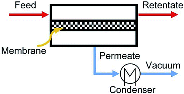 | ||
| Fig. 10 Schematic diagram of pervaporation process. Reproduced with permission from ref. 170. Copyright 2016 Elsevier Ltd. | ||
The first application of pervaporation for the selective removal of volatile substances from ILs was reported by Schäfer and coworkers.171 They tested different hydrophilic and hydrophobic polymeric membranes, i.e., poly(octylmethyl-siloxane) (POMS), polyether block amide (PEBA) and poly(vinyl alcohol) (PVA) to recover volatile solutes from [C4mim][PF6], with recovery efficiency of 99.2% for all solutes tested. Sun et al.172 evaluated a commercially available pervaporation system for dehydration and recycling of [C2mim][Ac] which was used for lignocellulosic pretreatment. The separation factor (defined as eqn (2)) as high as 1500 was observed, resulting in over 99.9 wt% recovery of [C2mim][Ac] from aqueous solution.
 | (2) |
The MD operation can be divided into four classes: (i) direct contact membrane distillation (DCMD), (ii) air-gap membrane distillation (AGMD), (iii) sweep gas membrane distillation (SGMD) and (iv) vacuum membrane distillation (VMD). The DCMD has been used for concentration of ILs from aqueous solution recently.68,173,174 The driving force of DCMD is the difference in the vapor pressure of a solution at different temperatures.175 During the DCMD process, the mixed feed solution is heated to a higher temperature than that in the permeate solution on the opposite side of the membrane. The hot water vapor molecules pass through the membrane and are condensed on the distillate side, while the salt or other contaminant ions are remained on the feed side (Fig. 11). The primary application of membrane distillation to concentrate ILs aqueous solution was reported by Lynam et al.68 Two ILs ([C2mim][Ac] and 1-ethyl-3-methylimidazolium formate ([C2mim][O2CH])) were concentrated from 5 wt% to 50 wt%. Subsequently, another technique, VMD, was proposed by Wu et al.173 to separate and concentrate the aqueous solution of [C4mim][Cl]. In their work, a polyacrylonitrile-based (PAN-based) hydrophobic membrane was prepared and utilized. A final IL concentration of 65.5 wt% with a total recovery over 99.5% was achieved. However, they found that due to the high viscosity and high polarity of hydrophilic ILs, membrane fouling would happen during the membrane distillation process, which is an essential issue to be investigated. After careful tests, Wu et al.173 pointed out possible membrane fouling mechanisms, including the [C4mim][Cl] deposition, the top layer wetting and the internal pore wetting. The deposited foulants could be removed readily by water flushing. However, once the wetting happened, it was difficult to realize a complete cleaning for the wetted membrane. Further research by the same group revealed that the chemical properties of membrane surface exerted more significant impact on membrane fouling than the surface morphology.174
 | ||
| Fig. 11 Direct contact membrane distillation process. Reproduced with permission from ref. 68. Copyright 2015 Elsevier Ltd. | ||
Technically, the electrodialysis could be effective for IL recovery due to the electrolyte nature of IL.176–179 Wang et al.177 employed electrodialysis to recover [C4mim][Cl] from water. The highest recovery ratio could reach 85.2%. Trinh et al.176 performed the recovery of [C4mim][Cl] with electrodialysis treatment from the aqueous mixture obtained after cellulose fractionation. Results indicated that the performance of electrodialysis was decreased owing to the deposition of foulants (mainly lignin depolymerization products) on the ion exchange membranes. Considering this fouling phenomenon, Liang et al.179 proposed a hybrid membrane-based methodology of electrodialysis in combination with ultrafiltration to recover the [C4mim][Br] after biomass fractionation, shown in Fig. 12. Ultrafiltration was employed to remove the residual lignin in IL solutions at first, which could reduce the major pollutant from lignin derivative that would locate at the anion exchange membrane. The highest overall IL recovery ratio reached 75.2%.
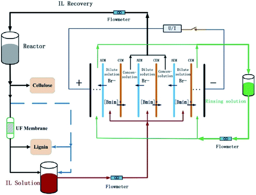 | ||
| Fig. 12 Procedure for IL-based biomass fractionation and IL recovery via the hybrid of electrodialysis with ultrafiltration. Reproduced with permission from ref. 179. Copyright 2015 Elsevier Ltd. | ||
2.5. Aqueous two-phase extraction
Aqueous two-phase extraction (ATPE) is based on the formation of the aqueous two-phase systems (ATPS), also known as aqueous biphasic systems (ABS). The ATPS could be formed when two immiscible phases (both soluble in water), e.g., polymer/polymer, polymer/salt or salt/salt, etc., are brought into the contact with each other above the critical concentration at a specific temperature.180 The aqueous two-phase extraction has proven to be a rapid, low-cost and scalable technology for separation and purification of antibiotics, enzymes, therapeutic proteins, etc.181–183 Through the aqueous two-phase extraction, the ILs aqueous solution could be separated into two phases, allowing the ILs to be concentrated or recovered in the IL-rich phase. Generally, the two phases could be formed through adding chemicals or changing temperature.Inorganic salts. A variety of inorganic salts, i.e., potassium salts,31,62,184–189 sodium salts190,191 and aluminum salts,192,193 etc., have been used for the preparation of IL-based ATPS. Deng et al.186 employed ATPS based on 1-allyl-3-methylimidazolium chloride ([Amim][Cl]) and potassium salts (K3PO4, K2HPO4 and K2CO3) for the recovery of [Amim][Cl]. They observed that different salts exerted different effects on the recovery of [Amim][Cl]. The recovery efficiency decreased in the order of K3PO4 > K2HPO4 > K2CO3. Similar results were obtained by Li et al.190 They used ATPS with sodium salts (Na3PO4, Na2CO3, Na2SO4, NaH2PO4 and NaCl) to recover [C4mim][BF4] with the recovery efficiency of 98.77%. Neves et al.192 initially proposed a recovery of imidazolium-, pyridinium-, and phosphonium-based ILs from aqueous solution making use of two aluminium-based salts (Al2(SO4)3 and AlK(SO4) 12H2O). At least 96% of the ionic liquids could be recovered.
The formation and stability of IL-based ATPS are found to be dependent on the structures of ILs such as cation types, lengths of alkyl chain and the anions. Bridges et al.62 investigated the effect of cationic cores of ILs on the formation of ATPS. Five species (K3PO4, K2HPO4, K2CO3, (NH4)2SO4 and KOH) were selected to induce the phase separation of imidazolium-, pyridinium-, quaternary ammonium- and phosphonium-based ILs. The ability of ILs to form ATPS could be enhanced through increasing the hydrophobicity of cationic core, i.e., [P4444][Cl] > [N4444][Cl] > [C4-Py][Cl] > [C4mim][Cl]. The positive charge on imidazolium- and pyridinium-based ILs is more delocalized over the ring compared to the quaternary ammonium- and phosphonium-based ILs, which allows the imidazolium and pyridinium cores to interact with water and thus disfavours the phase separation. Ventura et al.185 evaluated the formation of ATPS based on imidazolium-, pyridinium-, pyrrolidinium- and piperidinium-based ILs with the salts (K2HPO4 or a mixture of K2HPO4/KH2PO4). Results showed that six-membered ILs (pyrrolidinium and piperidinium) were more easily to form the ATPS than five-membered ILs (imidazolium and pyridinium), which could be ascribed to the difference in the charge density and molar volume of these cationic cores. Neves et al.193 studied the effect of alkyl chain length on the ATPS formation involving hydrophilic imidazolium-based ILs and K3PO4. They found that increasing the length of alkyl chain of ILs could increase the phase separation capability. They believed that it was ascribed to the longer alkyl chain ILs which were more hydrophobic and thus aggregate more easily during the phase separation. Furthermore, Pei et al.184 found that the phase-forming ability of the ILs follows the order: [C4mim][Br] > [C4mim][Cl], [C6mim][Br] > [C6mim][Cl], indicating that bromide-based ILs presented higher aptitude to form ATPS than their chloride-based counterparts. This observation was in good agreement with the data reported by Coutinho and co-workers.194
Cláudio et al.191 proposed a two-step ATPS scheme to recover the ionic liquids. They conducted an IL-recyclable extraction to extract a kind of antioxidant (gallic acid). As shown in Fig. 13, the gallic acid was firstly extracted into the IL-rich phase using Na2SO4-based ATPS. Subsequently, the IL-rich phase containing gallic acid was separated and formed a new ATPS with the addition of Na2CO3. Almost all of gallic acids were stripped and obtained through this back-extraction. While the ILs were regenerated for subsequent reuse. They evidenced that in each cycle among four sequential partitioning experiments, the recovery of ionic liquids could reach up to 94% or even 95%.
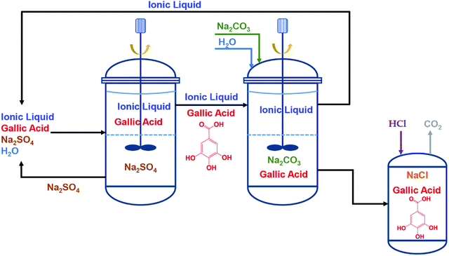 | ||
| Fig. 13 Flow chart of the two-step approach for a IL-recyclable ATPS extraction of gallic acid: 1st step – ATPS using Na2SO4 extracts the biomolecule into the IL-rich phase; 2nd step – ATPS using Na2CO3 leads to the back-extraction and recovery of gallic acid from the IL phase. Finally, the IL is regenerated for a subsequent reutilization in a new cycle. Reproduced with permission from ref. 191. Copyright 2014 The Royal Society of Chemistry. | ||
Carbohydrates. Although the addition of inorganic salts could be successfully applied to form ATPS, the concentration of inorganic salts in the salt-rich phase was often very high, even resulting in secondary treatment or environmental problem. To avoid this problem, great attempts have been made to seeking the covalent compound, i.e., carbohydrates, for inducing phase separation of ILs aqueous solution.195,196 Wu et al.195 firstly proposed an ATPS composed of hydrophilic ILs ([Amim][Cl], [Amim][Br], [C4mim][BF4]) and sucrose. An upper IL-rich phase and a lower sucrose-rich phase were generated eventually. However, the recoveries of ILs were not satisfying, just 74% for [C4mim][BF4], 65% for [Amim][Br] and 63% for [Amim][Cl]. Their subsequent work196 applied four types of saccharides (sucrose, glucose, xylose and fructose) to form ATPS with [C4mim][BF4]. It was found that the highest recovery for [C4mim][BF4] was only 74%. Although the IL-carbohydrate-ATPS is more environmentally friendly compared with the IL-inorganic salt-ATPS, the extraction efficiency still needs to be enhanced.
In addition to the two IL-based ATPS induced by inorganic salt and carbohydrate, other chemicals such as polymers197 and amino acid198 have also been studied to form ATPS. However, most of the work are still in the lab.
Carbon dioxide. Carbon dioxide (CO2) is nontoxic, cheap and recyclable, thus it is often used as the trigger for process switching in many cases. Introduction of CO2 can induce either the formation of IL-based ATPS,53,199 or the direct phase transition of the IL/water mixture.63 Xiong et al.53 investigated the phase separation of aqueous solutions of ILs and amines upon the introduction of CO2 at 25 °C and ambient pressure. The formed ATPS consisted of an ammonium-salt-rich upper phase and an IL-rich lower phase. It was found that the phase separation ability of the ammonium salts decreased in the order: 1,2-propylenediamine > monoethanolamine > diethanolamine > N-methylmonoethanolamine > N-methyl-diethanolamine > triethanolamine (i.e., 1,2-PDA > MEA > DEA > MMEA > MDEA > TEA). For a specific amine, the recovery efficiency of the ILs decreased in the order: 1-butyl-3-methy-limidazolium tetrafluoroborate > 1-butylpyridinium tetrafluoroborate > 1-butylpyridinium trifluoromethanesulfonate (i.e., [C4mim][BF4] > [C4-py][BF4] > [C4-py][TfO]), which was correlated with the hydrophobicity of these ILs. The one-step recovery efficiency of ILs could reach up to 99% in the presence of primary or secondary amines. Moreover, it was found that the phase separation of the tetrabutylphosphonium N-trifluoromethanesulfonyl leucine ([P4444][Tf-Leu])/water mixture could be induced by bubbling CO2 at 20 °C and atmospheric pressure.63 As shown in Fig. 14, the IL phase was coloured by Nile blue. After injection of CO2, the clear and homogeneous solution (Fig. 14a) turned turbid with bubbling time (Fig. 14b–d). The mixture was separated after 5 min (Fig. 14e). The separated phase could be changed back to homogeneous state when N2 gas was bubbled to remove the CO2 (Fig. 14e–g).
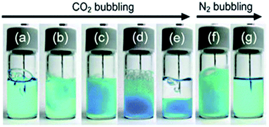 | ||
| Fig. 14 Phase change of the IL/water mixture driven by CO2/N2 gas bubbling. CO2 gas was bubbled into the mixture: (a) CO2 gas bubbling just started, (b), (c), (d), and (e) correspond to 1, 2, 3, and 5 min after bubbling, respectively. Then, N2 gas was bubbled for (f) 1 min and (g) 10 min, respectively. IL phase was coloured by Nile blue. All the processes were carried out at 20 °C. The bubbled gas was leaked through another syringe (not seen). Reproduced with permission from ref. 63. Copyright 2011 The Royal Society of Chemistry. | ||
 | ||
| Fig. 15 Temperature dependence of the phase behavior of a [P4444]-[Tf-Leu]/water mixture. Reproduced with permission from ref. 200. Copyright 2007 Wiley-VCH. | ||
2.6. Crystallization
Crystallization is a natural or artificial process by which the atoms or molecules are highly organized into a structure known as crystal. Generally, crystallization can be attained by means of cooling or compression, as illustrated in Fig. 16.202 Different methods including temperature- and pressure-induced crystallization have been recently investigated for purification of ILs.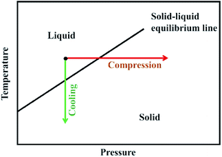 | ||
| Fig. 16 Schematic drawing of compression and cooling. Reproduced with permission from ref. 202. Copyright 2010 American Chemical Society. | ||
Zone melting. During the zone melting, a molten zone traverses a long ingot of impure solid with a specific velocity.205 As the molten region moves along, it melts the solid at its forward edge and leaves a wake of purer substance solidified behind it, while the impurities concentrate in the melt and are moved to one end of the ingot. Choudhury et al.54 was the first to determine the features (e.g., nature of hydrogen bonding between the cation and anion, anion disorder and crystal packing, etc.) of the crystal structures of five ILs (1-ethyl-3-methylimidazolium tetrafluoroborate ([C2mim][BF4]), 1-butyl-3-methylimidazolium hexafluorophosphate ([C4mim][PF6]), 1-butyl-3-methylimidazolium trifluoromethylsulfonate ([C4mim][TfO]), 1-hexylpyridinium bis(trifluoromethanesulfonyl)amide ([C6-py][Tf2N]) and 1-butyl-1-methylpyrrolidinium bis(trifluoromethanesulfonyl)amide ([Bmpyr][Tf2N])). A small sample of an IL was cooled down to −150 °C at 6 °C min−1 to turn into a solid followed by being heated at steps of 10 °C. The single crystals of five ILs grew from their melts eventually. In their subsequent work,206 the single crystals of another two ILs ([C2mim][TfO] and [C2mim][Tf2N]) were generated by using a zone-melting technique. Similar results have been obtained by Konig et al.32 when purifying the [C2mim][Cl] and [C2mim][Br] through melt crystallization with the purity up to 99.9 wt%.
Layer melt crystallization. Layer melt crystallization could be achieved by freezing a melt under controlled conditions of a heat exchange, where a solid layer of crystals is generated adjacent to a cooled surface.207 The layer melt crystallization was also successfully applied for the purification of some ILs. Konig et al.32 conducted the static layer crystallization at lab scale for purification of [C2mim][Cl] and [C2mim][Br]. The content of impurity (1-methylimidazole) in IL decreased from 5 wt% to 1.5 wt%, and high pure (>99%) [C2mim][Cl] was obtained after the crystallization. As for the [C2mim][Br], for the first time of crystallization, the purity of IL was increased from 87 wt% to 97 wt%. To enhance the purification, Solà Cervera et al.208 proposed a complete recycling concept for the [C2mim][Tf2N]-AlCl3-based electrolytes in aluminum electrodeposition, the central part of which was the application of layer melt crystallization technique for purification of the spent electrolyte. Two main compounds in the spent electrolyte ([C2mim][Cl] and AlCl3) were recovered through crystallization of the component [C2mim][AlCl4]. The impurities decreased to pretty low concentrations with ILs recovery yields of at least 65%.
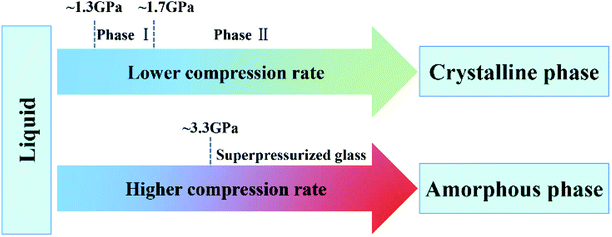 | ||
| Fig. 17 Pressure-induced phase transitions of [C2mim][TfO]. Reproduced with permission from ref. 214. Copyright 2015 American Chemical Society. | ||
2.7. Force field
For some specific ILs systems, dispersions formed by hydrophobic ILs or solutions of magnetic ILs, other methods based on the employment of gravity field, centrifugation66 and magnetic fields33,59,218–220 have been proposed for recovery of ILs.A successful example of an industrial process using ionic liquid is the BASIL (Biphasic Acid Scavenging utilizing Ionic Liquids) process developed by BASF for the production of the alkoxyphenylphosphine (Fig. 18a).43,221 In this process, the dichlorophenylphosphine was reacted with ethanol and 1-methylimidazole. The ionic liquid, i.e., 1-methylimidazolium chloride ([Hmim][Cl]), was formed as a by-product. After reaction, two liquid phases were formed: an upper phase of pure product (diethoxyphenylphosphine) and a lower phase of ionic liquid, which could be easily removed by gravity separation (Fig. 18b).43 Subsequently, the ionic liquid was deprotonated by reacting with sodium hydroxide to reform the 1-methylimidazole. The BASIL process is now run in a small jet reactor (Fig. 18c) with a capacity and yield of 690![[thin space (1/6-em)]](https://www.rsc.org/images/entities/char_2009.gif) 000 kg m−3 h−1 and 98%, respectively.39
000 kg m−3 h−1 and 98%, respectively.39
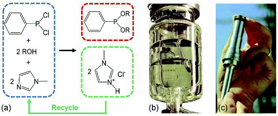 | ||
| Fig. 18 The BASIL process: (a) schematic of the synthesis route of alkoxyphenylphosphines;221 (b) the BASIL reactor. After the reaction two clear liquid phases are obtained: the upper being the pure product the lower being the ionic liquid;43 (c) the BASIL jet stream reactor.39 | ||
The IFP (France) has developed a biphasic process named Difasol, where the chloroaluminate(III) ionic liquid is used as solvent for the nickel-catalysed dimerisation reactions.222 The process was operated in a pilot plant. As shown in Fig. 19, a representative industrial feed (C4 raffinate II), composed of 70 wt% butene (27 wt% of which is 1-butene) and 1.5 wt% isobutene (the remainder being n-butane and isobutane) was introduced continuously into the mechanically stirred type reactor containing the ionic liquid and the nickel catalyst. The reactor was operated full of liquid. The effluent (a mixture of the two liquid phases) left the reactor via an overflow and was transferred to a phase separator. The separation of the ionic liquid from the product occurred rapidly and completely (favoured by the difference in densities). The ionic liquid phase containing the catalyst was recycled to the reactor, while the product was transferred to the washing and distillation section. After continuous run of 5500 hours, the volume of the ionic liquid phase did not change and no ionic liquid was detected in the product. The conversion of butenes was maintained above 70 wt% and the octene selectivity was around 95 wt%.
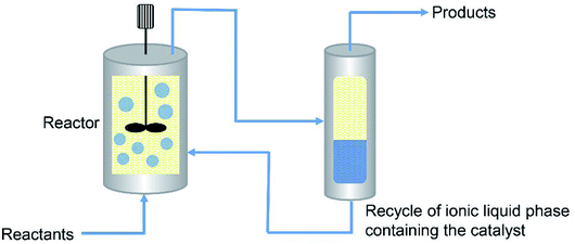 | ||
| Fig. 19 Schematic of the Difasol process. Reproduced with permission from ref. 222. Copyright 2007 Institut français du pétrole. | ||
The University of Petroleum (China) developed an alkylation process of isobutane and C4 olefins for manufacturing alkylate oil,223 where a composite catalyst is used based on the chloroaluminate ionic liquid and metal compounds. After the reaction, the ionic liquid and the alkylation product would form two phases, which could be readily separated.
 | ||
| Fig. 20 Heating [DBU-Bu][FeBrCl3] solution from 24 °C to 50 °C and magnetic separation of [DBU-Bu][FeBrCl3] from water at 50 °C. Reproduced with permission from ref. 59. Copyright 2016 the Royal Society of Chemistry. | ||
2.8. Combined methods
Due to the complexity of chemical reactions or separation systems in practical processes, the single method may not meet the satisfaction of total recovery of ILs or cannot reach the requirement of purity. To improve the recovery or purification efficiency, several techniques would be utilized in conjunction during a specific process. Herein, examples for combining different methods to recover ILs are slightly presented here.As mentioned above, the ILs have been used as solvents or catalysts in a wide array of reactions. After completion of the reaction, ILs can be separated from both non-volatile and volatile products or impurities by extraction with organic solvents followed by distillation.225,226 In some cases, the filtration is also needed to separate the solid chemicals at first.52,67 For instance, Khan et al.52 conducted one-pot conversion of cellulose to levulinic acid using dicationic IL (1,1-bis(3-methylimidazolium-1-yl) butane hydrogensulfate ([C4(mim)2][2(HSO4)(H2SO4)2])) as a catalyst. The reaction mixture was diluted with deionized water followed by passing through Teflon filter paper. After filtration of the insoluble humin, the ethyl acetate was added to the mixture for extraction of levulinic acid, obtaining an upper phase containing levulinic acid and lower phase containing IL and water. The IL from lower aqueous phase was recovered using vacuum rotary. According to the NMR and FTIR spectral analysis, no extra peak appeared in the used IL, confirming the purity and stability of IL under the experimental conditions. Moreover, IL was recycled up to 4 times with less than 5% weight loss. Another example for ILs recycling by combination of filtration, extraction and evaporation was given by Bogdanov et al.67 Their study aimed at regenerating 1-butyl-3-methylimidazolium acesulfamate ([C4mim][Ace]) which was used to extract the bioactive alkaloids S-(+)-glaucine from aerial parts of G. flavum Crantz (Papaveraceae). The whole process is depicted in Fig. 21. When the IL-supported solid–liquid extraction for plant material was finished, the residual biomass was filtered and collected for recovery and regeneration of the rest IL residing in the matrix pores of biomass. The IL in the enriched crude glaucine was extracted with chloroform. After phase separation, the upper IL-aqueous phase was set aside for subsequent IL regeneration. As for the block of IL regeneration, the collected residual biomass was washed by water. The IL aqueous solution obtained after washing was mixed with the materials came from extraction. After water removal under reduced pressure, the residue was dissolved in dry dichloromethane followed by the filtration of the solution and the evaporation of organic solvent successively. Finally the residue was mainly consisted of [C4mim][Ace]. The IL was successfully recovered and reused in ten consecutive extraction cycles without loss of performance. However, this procedure is limited for industrial application due to the requirements of organic solvents like chloroform and dichloromethane with toxicity, thus screening more benign solvents is becoming much more essential.
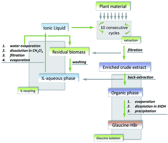 | ||
| Fig. 21 Block diagram for the production of glaucine from plant material and recovery of ionic liquids. Reproduced with permission from ref. 67. Copyright 2015 Elsevier Ltd. | ||
Solà Cervera et al.208 designed an integral recycling concept for [C2mim][NTf2]-AlCl3-based electrolytes which was used for the electrodeposition of aluminum. Fig. 22 displays a complete flow sheet of recycling steps, which can be divided into three parts: the first part is crystallization of the spent electrolyte, the second is correlated with further extraction of the residue after crystallization, while the third part is about the two step nanofiltration for concentration and separation of the ionic components in the washing stream. (i) After completion of the electrodeposition process, two main components in the spent electrolyte ([C2mim][Cl] and AlCl3) are recovered and purified by layer melt crystallization in the form of [C2mim][AlCl4]. To change the electrolyte composition to the region where the compound of [C2mim][AlCl4] can be crystallized in a high yield, the [C2mim][Cl] needs to be added into the spent electrolyte before crystallization. To generate a reusable electrolyte with the same composition as the fresh electrolyte, different amounts of [C2mim][Tf2N] and AlCl3 have to be added to the crystallization product. It was found that the impurities could be decreased to pretty low concentrations with ionic liquids recovery at least 65% where the compound of [C2mim][AlCl4] can be crystallized in a high yield, the [C2mim][AlCl4] has been added into the spent electrolyte before crystallization. To generate a reusable electrolyte with the same composition as the fresh electrolyte, different amounts of [C2mim][Tf2N] and AlCl3 have to be added to the crystallization product. It was found that the impurities could be decreased to pretty low concentrations with ionic liquids recovery of at least 65%. (ii) The residue of the crystallization such as additives, decomposition products apart from [C2mim][Cl], AlCl3 and [C2mim][Tf2N] are hydrolyzed by adding water, where most of [C2mim][Tf2N] are recovered with the lower organic phase. If necessary, [C2mim][Tf2N] can be further purified by vacuum distillation or crystallization (conditioning step in Fig. 22). After hydrolysis of these residue, the recovery of valuable component (i.e., [C2mim][Cl]) from aqueous solution is achieved by multistage extraction with dichloromethane. (iii) After aluminum coating is completed, a part of the electrolyte will remain adhered to the workpiece, which also needs to be recovered and recycled. Water as a washing media is proposed to clean the workpiece and recover the electrolyte. The washing stream firstly passes through one nanofiltration membrane, where water is recovered. The concentrated IL solution (retentate) is subsequently fed into the second different membrane in which Al3+ and [C2mim]+ ions are separated. During the whole recycling process, only waste solutions containing aluminum salts, very low concentrations of the ILs and some impurities are generated. However, it is just a semiquantitative concept, which needs to be further applied and validated.
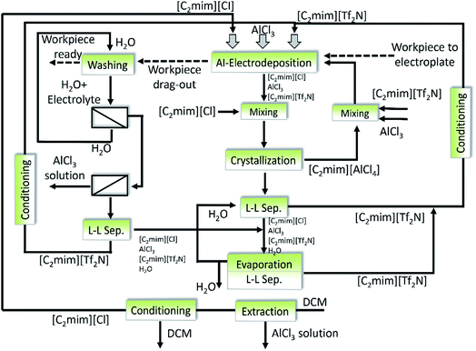 | ||
| Fig. 22 Complete recycling concept for the [C2mim][Tf2N]-AlCl3-based electrolytes in aluminum electrodeposition. Reproduced with permission from ref. 208. Copyright 2010 WILEY-VCH. | ||
The Eastman Chemical Company had been running a process for the isomerisation of 3,4-epoxy-1-butene to 2,5-dihydrofuran between 1996 and 2004, during which a combination of distillation and extraction was employed for the ionic liquids recovery.39,227 This process was operated in a plant with capacity of 1400 metric tons per year (Fig. 23). The mixture of a Lewis acid (trialkyltin iodide) and a Lewis basic (tetraalkylphosphonium ionic liquid ([P8,8,8,18][I])) was used as the catalyst. After reaction, the 2,5-dihydrofuran and one of the by-product (crotonaldehyde) were distilled out in a wiped-film evaporator. Another by-product (oligomer) was extracted from the catalysts with hydrocarbon in a continuous, counter-current and liquid–liquid extractor. After distillation of the hydrocarbon, the catalysts could be reused for isomerisation. The plant is now idle due to the declined market for the product.
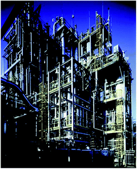 | ||
| Fig. 23 Texas Eastman Division EpB Chemical Semiworks Plant, Longview, Texas.39 | ||
3. Discussions on the recovery and purification technologies for ionic liquids
As mentioned above, there are different methods for the recovery and purification of ionic liquids. However, due to the differences in the properties of ionic liquids, the compositions of ionic liquids solutions and the specific requirements of operational cost, each of the technologies for the recovery and purification of ionic liquids from solutions possesses its optimal application scope. Accordingly, it is necessary to know the applicable scope of each method before the process design. Characteristics, advantages and disadvantages of different ILs recovery methods are summarized in Table 4. The ILs and their corresponding recovery methods which are mentioned in the review are presented in Tables 5 and 6.| Methods | Characteristics | Advantages | Disadvantages | |
|---|---|---|---|---|
| Distillation | Distillation of volatile compounds | ILs are remained as residue. | Simple to operate | Energy consuming |
| Distillation through reactions of ILs | ILs are distilled as neutral species or intact ion pairs. | Low impurity | ||
| Extraction | Extraction with water | Extract hydrophilic solutes from hydrophobic ILs. | Simple, low cost | Limited application |
| Extraction with organic solvents | Extract hydrophobic solutes from ILs. | Cross-contamination | ||
| Extraction with scCO2 | Both hydrophobic and hydrophilic ILs can be separated. | Requirement of special apparatus | ||
| Adsorption | Adsorption by ACs | Affected by pore structure and surface chemistry of ACs. | Non-destructive, suitable for diluted solutions | Insufficient desorption data |
| Adsorption by soils and sediments | Affected by TOC and CEC of soils. | |||
| Adsorption by ion exchange resins | Affected by functional group and ionic form of resins. | |||
| Membrane separation | Pressure-driven membrane techniques | ILs can be either permeated or rejected. | Low energy demand, selective permeability | Concentration polarization |
| Pervaporation | ILs are rejected while volatile species are permeated. | Large membrane area | ||
| Membrane distillation | ILs are rejected while water vapor is permeated. | Membrane fouling | ||
| Electrodialysis | Cations and anions of ILs cross ion exchange membranes. | Membrane fouling | ||
| Aqueous two-phase extraction | ATPE based on chemicals addition | Formation of ATPS by adding salts, carbohydrates or CO2. | Rapid, low-cost, scalable | High concentration of salts or organics |
| ATPE based on changing temperature | Formation of ATPS or LCST-type phase separation. | Limited application | ||
| Crystallization | Solution crystallization | ILs are crystallized from solution. | High purity | Energy consuming |
| Melt crystallization | ILs are crystallized from melt. | |||
| Pressure-induced crystallization | ILs are crystallized under high pressure. | |||
| Force field | Gravity separation | ILs are separated from immiscible liquids. | Simple, low energy demand | Low separation rate. |
| Centrifugation | ILs emulsion were separated by centrifugation. | Small throughput | ||
| Magnetic separation | ILs are separated by magnetic field. | Limited application | ||
| Methods | Imidazolium | |||||||||||
|---|---|---|---|---|---|---|---|---|---|---|---|---|
| Cl−, Br− | BF4− | PF6− | MS− | TfO− | Tf2N− | O2CH−, Ac−, Pr− | SO42−, NO2− | DMP− | BETI− | FeCl4− | ||
| Distillation | Distillation of volatile compounds | ✓45,78–81 | ✓46 | ✓46 | ✓46 | ✓46 | ✓46 | ✓27,81,84,85 | ||||
| Distillation through reaction of ILs | ✓44,100 | |||||||||||
| Extraction | Extraction with water | ✓65,110,111 | ✓51 | |||||||||
| Extraction with organic solvents | ✓78,116 | ✓114,115 | ✓117 | ✓118 | ✓113 | ✓69 | ||||||
| Extraction with scCO2 | ✓50,130 | ✓28,50,123,124,127–129 | ✓50 | ✓50,125,126 | ||||||||
| Adsorption | Adsorption by ACs | ✓48,55,70,132–137,149 | ✓48,70 | ✓21,48,70,131,136 | ✓48,132 | ✓48,70,132,133 | ✓48,70,132,133 | ✓132 | ||||
| Adsorption by soils and sediments | ✓47,139,141,143–146,149 | ✓140,142 | ✓142 | |||||||||
| Adsorption by ion exchange resins | ✓149,150,152 | ✓152 | ✓152 | ✓151,153 | ||||||||
| Membrane separation | Pressure-driven membrane techniques | ✓166 | ✓30,166 | ✓30 | ✓72 | |||||||
| Pervaporation | ✓171 | ✓172 | ||||||||||
| Membrane distillation | ✓173 | ✓68 | ||||||||||
| Electrodialysis | ✓176–179 | |||||||||||
| Aqueous two-phase extraction | ATPE based on chemicals addition | ✓31,62,184–187,189,193–195 | ✓53,190,195,196,199 | ✓191 | ✓191,192,194,199 | ✓188,194 | ✓191 | |||||
| Crystallization | Solution crystallization | ✓203 | ✓71 | |||||||||
| Melt crystallization | ✓32 | ✓54 | ✓54 | ✓54,206 | ✓206 | |||||||
| Pressure-induced crystallization | ✓202 | ✓214 | ||||||||||
| Force field | Gravity separation | ✓43 | ||||||||||
| Centrifugation | ✓66 | ✓66 | ||||||||||
| Magnetic separation | ✓33,218 | |||||||||||
| Methods | Pyridinium | Pyrrolidinium | Ammonium | Phosphonium | ||||||||||||
|---|---|---|---|---|---|---|---|---|---|---|---|---|---|---|---|---|
| Cl−, Br− | BF4− | PF6− | TfO− | Tf2N− | Cl−, Br− | Tf2N− | Cl− | FeCl4− | ECOENG500 | CTMA | Cl− | [Tf-Leu]− | CYPHOS IL 101 | CYPHOS IL 104 | ||
| Distillation | Distillation of volatile compounds | ✓57 | ✓76 | |||||||||||||
| Distillation through reaction of ILs | ✓109 | |||||||||||||||
| Extraction | Extraction with organic solvents | ✓77 | ||||||||||||||
| Adsorption | Adsorption by ACs | ✓55,134,135 | ✓132,136 | ✓132,133 | ✓134 | ✓132 | ✓132 | ✓132 | ||||||||
| Adsorption by soils and sediments | ✓47,143,144 | |||||||||||||||
| Membrane separation | Pressure-driven membrane techniques | ✓56 | ✓75 | ✓75 | ||||||||||||
| Aqueous two-phase extraction | ATPE based on chemicals addition | ✓185 | ✓53,199 | ✓53,199 | ✓192 | ✓63 | ||||||||||
| ATPE based on changing temperature | ✓201 | ✓200 | ||||||||||||||
| Crystallization | Melt crystallization | ✓54 | ✓54 | |||||||||||||
| Force field | Magnetic separation | ✓59 | ||||||||||||||
Distillation is considered to be an easily operated method for recovery of ILs. The distillation process could be conducted through vaporization of the water or other volatile solvents (e.g., methanol, acetone, etc.), where ILs (either hydrophilic or hydrophobic) are remained as the residue. This is especially suitable to separate high concentration ILs solutions and usually ILs with high purity could be obtained. The distillation could also be carried out through the reaction of ILs (e.g., 1,3-substituted imidazolium ILs). However, it would increase the operational difficulty, and often the impurities would occur in the recovered ILs. Furthermore, although some aprotic ILs could be distilled as intact ion pairs without decomposition, the harsh distillation conditions would cause the increased operation costs. The traditional distillation is a common method in industrial application. However, it often exhibits high energy consumption and a risk of thermal decomposition of the substances. Therefore, the pre-concentration of the ILs solution may be an attractive option to run the distillation process in a more energy-saving way.
Extraction is a relatively simple and low-cost method which shows potential in recovering ILs from solutions containing non-volatile or thermally sensitive substances. Extraction with water is suitable to separate the hydrophilic compounds from hydrophobic ILs (e.g., [C4mim][PF6] and [C4mim][Tf2N]). However, it is limited by the hydrophilicity of ILs. Extraction with organic solvents could be employed to separate either hydrophobic (e.g. [C4mim][PF6]) or hydrophilic ILs (e.g., [C2mim][Ac]), and it could also be used in different fields (organic synthesis reaction, extraction separation, biomass pretreatment, etc.). However, the use of organic solvents would cause the cross-contamination and other environment problems. As a kind of nontoxic and easy to separate solvent, the scCO2 is able to separate a series of organic solutes (e.g., naphthalene, phenol, benzoic acid, methanol and hexane, etc.) from the hydrophobic ILs (e.g., [C4mim][PF6]). For the mixture of IL and some polar organic compounds (e.g., ethanol and acetone), it is feasible to use scCO2 as the solvent only when the concentration of these organic compounds is pretty low (e.g., 10 mol%). High pressure CO2 could lead to the phase separation of some ILs ([C4mim][PF6], [PDmim][Tf2N], [C4mim][BF4] and [C4mim][TfO], etc.) aqueous solution. However, high ILs recovery efficiency is difficult to be achieved. Moreover, the high equipment costs should be considered when applying the scCO2 technology for ILs recovery.
As a low energy consuming method, the adsorption–desorption combined process would be a potential choice to recover ionic liquids, which is especially suitable for low concentration or diluted ILs aqueous solutions. The activated carbon is the mostly studied adsorbent. It has been used to adsorb a variety of ILs with different anions ([Tf2N]−, [PF6]−, [TfO]−, [BF4]−, [TFA]−, [Cl]− and [Br]−, etc.) and cations (ammonium, phosphonium, pyridinium, imidazolium and pyrrolidinium, etc.). The soils and sediments also show adsorption capacity for some hydrophilic ([Cnmim][BF4], [Cnmim][Cl] and [C4-4-mPy][Cl], etc.) and hydrophobic ILs (e.g., [C4mim][Tf2N]). The ion exchange resin could be used recover the cations of ILs ([Cnmim][Cl], [Cnmim][Ac], [Cnmim][BF4] and benzothiazolium ILs, etc.) from the aqueous solution or other solutions (e.g., ILs and glucose mixture solution). However, there exists an inherent drawback in this method that the anions of ILs could not be adsorbed and remain in the original solution. Additionally, other adsorbents such as carbonaceous materials, bacterial biosorbents and biochars have also been studied for the separation of some imidazolium based ILs ([Cnmim][Cl], [C2mim][Ac], etc.). Basically, the adsorption–desorption method would be good candidate for the preconcentration step of ILs, which could be further combined with distillation or other processes to lower the energy consumption. Furthermore, other efforts such as understanding of the adsorption mechanisms (thermodynamics and kinetics), improvement of the desorption efficiency and the adsorbent recyclability are still in need.
The method of membrane separation is of low energy demand and high selectivity. The pressure-driven membrane technique has been studied for recovery of different ILs ([C4mim][Cl], [C4mim][BF4], [Mmim][DMP], [Mmim][MS], [C4-3-mpy][BF4], CYPHOS IL 101, ECOENG500 and Ethaline200, etc.). Whereas, the permeate flux may be decreased during the pressure-driven membrane process due to the concentration polarization. Separation of volatile components such as water from ILs (e.g., [C4mim][PF6], [C2mim][Ac]) by pervaporation is independent on the osmotic pressure, but large membrane area may be required due to the low membrane flux. During the membrane distillation, water vapor permeates the hydrophobic membrane while ILs (e.g., [C2mim][O2CH], [C2mim][Ac] and [C4mim][Cl]) are remained. Additionally, electrodialysis could be applied to concentrate hydrophilic ILs (e.g., [C4mim][Cl], [C4mim][Br]) from aqueous solutions. It is worth noticing that concentrated ILs solutions, but not pure ILs are obtained after the membrane separation, thus the membrane technology could also be employed as a preconcentration process and combined with other methods such as distillation or extraction. Moreover, to facilitate the industrialization step of the recovery of ILs by membrane separation, more attempts should be made to reduce the membrane cost, decrease the membrane fouling and improve the membrane separation performance, etc.
The aqueous two-phase extraction, which is based on the formation of aqueous two-phase systems with no use of organic solvents, is regarded as an environmentally friendly method to recover hydrophilic ILs from aqueous solutions. Adding inorganic salts or carbohydrates could induce the phase separation of water and a variety of ILs (e.g., [C4mim][BF4], [Cnmim][Br], [Cnmim][Cl], [P4444][Cl], [N4444][Cl] and [C4-Py][Cl], etc.). However, this method could result in the increasing content of inorganic ions or organic compounds in aqueous solution. For aqueous solutions of some ILs (e.g., [C4mim][BF4], [C4-py][BF4] and [C4-py][TfO]) and amines, the ATPS could be formed upon the introduction of CO2 at ambient conditions. For aqueous solution of ILs prepared from amino acids (e.g., [P4444][Tf-Leu]), the ILs could be separated directly from water when CO2 is bubbled. With regard to ILs that exhibit LCST phenomenon (e.g., [P4444][Tf-Leu]) or thermo-reversible behaviour (e.g., [N11[2(N11)]0][Cl]), the direct phase separation or ATPS could be formed by changing the temperature. During the aqueous two-phase extraction, the recovery efficiency of ILs is still limited, which may be improved by further exploration of the thermodynamic models, seeking new IL-based aqueous two-phase systems, etc.
Crystallization could be used to obtain ILs with high purity. Crystals of some ILs (e.g., [C2mim][NO2], [C2mim][Br]) could be formed by solution crystallization. The melt crystallization is suitable to purify a variety of ILs such as [C2mim][Cl], [C4mim][BF4], [C4mim][PF6], [C4mim][TfO], [C6-py][Tf2N], etc. In addition, some ILs (e.g., [C4mim][PF6], [C2mim][TfO]) would crystallize under high pressure. However, purification of ILs by crystallization is also an energy consuming procedure.
Separation by force field is sometimes an easy method to be operated. The gravity separation has been the most widely used method to recover IL from immiscible liquids in industry, which is due to advantages of simple operation, low cost and no chemical additions. The centrifugation is suitable to recover hydrophobic ILs from dispersions or emulsions, but it is restricted by the low production. Furthermore, separation under the magnetic field could only be applied to recover magnetic ILs (e.g., [C4mim][FeCl4], [N1,1,1,12][FeCl4], etc.).
4. Conclusions and perspectives
Ionic liquids have been widely investigated and applied in many fields, including catalyst processing, material synthesis, extraction, desulfurization, hydrogenation, etc. However, due to their hygroscopicity or dissolution to the solvents, they are often contaminated by different chemicals, such as salts, water, hydrocarbon solvents, etc. Now, the recovery and purification of ionic liquids would be one of the biggest challenges before their industrial applications. From the energy and resources saving point of view, it is urgent and necessary to recover the ILs from the waste solutions, which is also a significant aspect for the industrialization of ionic liquids. During the last decades, different technologies, i.e., distillation, extraction, adsorption, membrane separation, aqueous two-phase extraction, crystallization and external force field separation, have been investigated for the recovery and purification of ILs either in lab or in pilot scale.Although some single methods would perform well in separating the ionic liquids from the solutions, most of their efficiencies are limited, resulting in low purity of the product or high cost or high energy input. More efforts should be made to optimize the ionic liquid recovery process in the future. On one hand, more in-depth and comprehensive fundamental researches of the separation technologies are required, e.g., the thermodynamic and kinetic analysis in the distillation and adsorption, optimization of the mass and heat transfer during the extraction, exploration of the deactivation and regeneration mechanisms of the membrane, energy optimization of the separation processes, etc. On the other hand, selecting and designing the combined recovery process is an attractive choice for the recovery of ILs. A comprehensive evaluation of the combined process should be conducted by considering the characteristics of ionic liquids (e.g., concentration, hydrophilicity and hydrophobicity, thermal sensitivity, etc.), the energy consumption, the equipment costs and the requirement of product purity, etc.
Conflicts of interest
There are no conflicts to declare.Acknowledgements
This work was financially supported by the National Natural Science Foundation of China (No. 21506155, No. 41471258).References
- T. Welton, Chem. Rev., 1999, 99, 2071–2084 CrossRef PubMed.
- J. P. Hallett and T. Welton, Chem. Rev., 2011, 111, 3508–3576 CrossRef PubMed.
- R. Hayes, G. G. Warr and R. Atkin, Chem. Rev., 2015, 115, 6357–6426 CrossRef PubMed.
- C. Austen Angell, Y. Ansari and Z. Zhao, Faraday Discuss., 2012, 154, 9–27 RSC.
- D. Mecerreyes, Prog. Polym. Sci., 2011, 36, 1629–1648 CrossRef.
- J. Pereira, P. S. Barber, S. P. Kelley, P. Berton and R. D. Rogers, Phys. Chem. Chem. Phys., 2017, 19, 26934–26943 RSC.
- A. Nusaibah Masri, A. Mutalib Mi and J. M. Leveque, Ind. Eng. Manage., 2016, 05, 388–395 Search PubMed.
- Z. Zhang, N. Kang, J. Wang, H. Sui, L. He and X. Li, Chem. Eng. Sci., 2018, 181, 264–271 CrossRef.
- J. Ding and D. W. Armstrong, Chirality, 2005, 17, 281–292 CrossRef PubMed.
- K. Takechi, Y. Kato and Y. Hase, Adv. Mater., 2015, 27, 2501–2506 CrossRef PubMed.
- R. Sheldon, Chem. Commun., 2001, 23, 2399–2407 RSC.
- W. Zheng, W. Xie, W. Sun and L. Zhao, Chem. Eng. Sci., 2017, 166, 42–52 CrossRef.
- A. Castro Grijalba, E. F. Fiorentini and R. G. Wuilloud, J. Chromatogr. A., 2017, 1491, 117–125 CrossRef PubMed.
- S. Riaño and K. Binnemans, Green Chem., 2015, 17, 2931–2942 RSC.
- J. Eßer, P. Wasserscheid and A. Jess, Green Chem., 2004, 6, 316–322 RSC.
- M. H. Ibrahim, M. Hayyan, M. A. Hashim and A. Hayyan, Renewable Sustainable Energy Rev., 2017, 76, 1534–1549 CrossRef.
- P. A. Z. Suarez, J. E. L. Dullius, S. Einloft, R. F. De Souza and J. Dupont, Polyhedron, 1996, 15, 1217–1219 CrossRef.
- L. Chen, C. Fink, Z. Fei, P. J. Dyson and G. Laurenczy, Green Chem., 2017, 19, 5435–5441 RSC.
- J. Fuller, R. T. Carlin and R. A. Osteryoung, J. Electrochem. Soc., 1997, 144, 3881–3886 CrossRef.
- A. Basile, A. I. Bhatt and A. P. O'Mullane, Nat. Commun., 2016, 7, ncomms11794 CrossRef PubMed.
- J. L. Anthony, E. J. Maginn and J. F. Brennecke, J. Phys. Chem. B, 2001, 105, 10942–10949 CrossRef.
- H. Luo, Sep. Sci. Technol., 2005, 40, 1245–1265 CrossRef.
- P. M. Dean, J. Turanjanin, M. Yoshizawa-Fujita, D. R. MacFarlane and J. L. Scott, Cryst. Growth Des., 2009, 9, 1137–1145 CrossRef.
- J. L. Shamshina, P. S. Barber and R. D. Rogers, Expert Opin. Drug Delivery, 2013, 10, 1367–1381 CrossRef PubMed.
- S. P. F. Costa, A. M. O. Azevedo, P. Pinto and M. Saraiva, ChemSusChem, 2017, 10, 2321–2347 CrossRef PubMed.
- M. Wagner and C. Hilgers, Ionic Liquids in Synthesis, Wiley-VCH, Weinheim, 2008, vol. 1, pp. 26–45 Search PubMed.
- P. Weerachanchai and J. M. Lee, Bioresour. Technol., 2014, 169, 336–343 CrossRef PubMed.
- L. A. Blanchard, D. Hancu, E. J. Beckman and J. F. Brennecke, Nature, 1999, 399, 28–29 CrossRef.
- L. Zhang, W. Cao, P. J. J. Alvarez, X. Qu, H. Fu, S. Zheng, Z. Xu and D. Zhu, Appl. Surf. Sci., 2018, 440, 821–829 CrossRef.
- J. Kröckel and U. Kragl, Chem. Eng. Technol., 2003, 26, 1166–1168 CrossRef.
- K. E. Gutowski, G. A. Broker, H. D. Willauer, J. G. Huddleston, R. P. Swatloski, J. D. Holbrey and R. D. Rogers, J. Am. Chem. Soc., 2003, 125, 6632–6633 CrossRef PubMed.
- A. König, M. Stepanski, A. Kuszlik, P. Keil and C. Weller, Chem. Eng. Res. Des., 2008, 86, 775–780 CrossRef.
- S. Hayashi and H. o. Hamaguchi, Chem. Lett., 2004, 33, 1590–1591 CrossRef.
- M. J. Earle and K. R. Seddon, Pure Appl. Chem., 2000, 72, 1391–1398 Search PubMed.
- T. Welton, Chem. Rev., 1999, 99, 2071–2083 CrossRef PubMed.
- S. Keskin, D. Kayrak-Talay, U. Akman and Ö. Hortaçsu, J. Supercrit. Fluids, 2007, 43, 150–180 CrossRef.
- P. Wasserscheid and W. Keim, Angew. Chem., 2000, 39, 3772 CrossRef.
- C. Yue, D. Fang, L. Liu and T. F. Yi, J. Mol. Liq., 2011, 163, 99–121 CrossRef.
- N. V. Plechkova and K. R. Seddon, Chem. Soc. Rev., 2008, 37, 123–150 RSC.
- H. Olivier-Bourbigou, L. Magna and D. Morvan, Appl. Catal., A, 2010, 373, 1–56 CrossRef.
- Y. Qiao, W. Ma, N. Theyssen, C. Chen and Z. Hou, Chem. Rev., 2017, 117, 6881–6928 CrossRef PubMed.
- S. P. M. Ventura, F. A. Silva, M. V. Quental, D. Mondal, M. G. Freire and J. A. P. Coutinho, Chem. Rev., 2017, 117, 6984–7052 CrossRef PubMed.
- K. R. Seddon, Nat. Mater., 2003, 2, 363 CrossRef PubMed.
- A. J. Jeapes, R. C. Thied, K. R. Seddon, W. R. Pitner, D. W. Rooney, E. J. Hatter and T. Welton, WO Pat., 0115175, 2000.
- K. Huang, R. Wu, Y. Cao, H. Li and J. Wang, Chin. J. Chem. Eng., 2013, 21, 577–584 CrossRef.
- S. H. Ha, N. L. Mai and Y. M. Koo, J. Chromatogr. A., 2010, 1217, 7638–7641 CrossRef PubMed.
- P. Stepnowski, W. Mrozik and J. Nichthauser, Environ. Sci. Technol., 2007, 41, 511–516 CrossRef PubMed.
- J. Lemus, J. Palomar, F. Heras, M. A. Gilarranz and J. J. Rodriguez, Sep. Purif. Technol., 2012, 97, 11–19 CrossRef.
- L. Zhang, J. Zhang, H. Fu, H. Zhang, H. Liu, Y. Wan, S. Zheng and Z. Xu, Microporous Mesoporous Mater., 2018, 260, 59–69 CrossRef.
- A. M. Scurto, S. N. V. K. Aki and J. F. Brennecke, Chem. Commun., 2003, 572–573 RSC.
- Y. Chen, H. Wang, Y. Pei and J. Wang, Sep. Purif. Technol., 2017, 178, 261–268 CrossRef.
- A. S. Khan, Z. Man, M. A. Bustam, C. F. Kait, A. Nasrullah, Z. Ullah, A. Sarwono, P. Ahamd and N. Muhammad, J. Cleaner Prod., 2018, 170, 591–600 CrossRef.
- D. Xiong, H. Wang, Z. Li and J. Wang, ChemSusChem, 2012, 5, 2255–2261 CrossRef PubMed.
- A. R. Choudhury, N. Winterton, A. Steiner, A. I. Cooper and K. A. Johnson, J. Am. Chem. Soc., 2005, 127, 16792–16793 CrossRef PubMed.
- A. Farooq, L. Reinert, J. M. Levêque, N. Papaiconomou, N. Irfan and L. Duclaux, Microporous Mesoporous Mater., 2012, 158, 55–63 CrossRef.
- S. Hazarika, N. N. Dutta and P. G. Rao, Sep. Purif. Technol., 2012, 97, 123–129 CrossRef.
- D. Dennewald, W. R. Pitner and D. Weuster-Botz, Process Biochem., 2011, 46, 1132–1137 CrossRef.
- A. Parviainen, R. Wahlström, U. Liimatainen, T. Liitiä, S. Rovio, J. K. J. Helminen, U. Hyväkkö, A. W. T. King, A. Suurnäkki and I. Kilpeläinen, RSC Adv., 2015, 5, 69728–69737 RSC.
- Q. Zhao, T. S. Herng, C. X. Guo, D. Zhao, J. Ding and X. Lu, RSC Adv., 2016, 6, 15731–15734 RSC.
- H. Luo, Y. Hu, R. Wang, W. Fan and G. Nan, Chem. Eng. Res. Des., 2018, 130, 29–34 CrossRef.
- A. He, B. Dong, X. Feng and S. Yao, J. Mol. Liq., 2017, 227, 178–183 CrossRef.
- N. J. Bridges, K. E. Gutowski and R. D. Rogers, Green Chem., 2007, 9, 177–183 RSC.
- Y. Kohno, H. Arai and H. Ohno, Chem. Commun., 2011, 47, 4772–4774 RSC.
- A. W. King, J. Asikkala, I. Mutikainen, P. Jarvi and I. Kilpelainen, Angew. Chem., Int. Ed. Engl., 2011, 50, 6301–6305 CrossRef PubMed.
- J. G. Huddleston, H. D. Willauer, R. P. Swatloski, A. E. Visser and R. D. Rogers, Chem. Commun., 1998, 1765–1766 RSC.
- J. F. Birdwell, J. McFarlane, R. D. Hunt, H. Luo, D. W. DePaoli, D. L. Schuh and S. Dai, Sep. Sci. Technol., 2006, 41, 2205–2223 CrossRef.
- M. G. Bogdanov, R. Keremedchieva and I. Svinyarov, Sep. Purif. Technol., 2015, 155, 13–19 CrossRef.
- J. G. Lynam, G. I. Chow, C. J. Coronella and S. R. Hiibel, Chem. Eng. J., 2016, 288, 557–561 CrossRef.
- P. Weerachanchai, K. H. Lim and J. M. Lee, Bioresour. Technol., 2014, 156, 404–407 CrossRef PubMed.
- J. Palomar, J. Lemus, M. A. Gilarranz and J. J. Rodriguez, Carbon, 2009, 47, 1846–1856 CrossRef.
- J. S. Wilkes and M. J. Zaworotko, J. Chem. Soc., Chem. Commun., 1992, 965–967 RSC.
- C. Abels, C. Redepenning, A. Moll, T. Melin and M. Wessling, J. Membr. Sci., 2012, 405–406, 1–10 CrossRef.
- Y. Beste, M. Eggersmann and H. Schoenmakers, Chem.-Ing.-Tech., 2005, 77, 1800–1808 CrossRef.
- U. Kreher, A. Rosamilia, C. Raston, J. Scott and C. Strauss, Molecules, 2004, 9, 387 CrossRef PubMed.
- S. Han, H. T. Wong and A. G. Livingston, Chem. Eng. Res. Des., 2005, 83, 309–316 CrossRef.
- M. Blahušiak, Š. Schlosser, J. Cvengroš and J. Marták, Chem. Pap., 2011, 65, 603–607 Search PubMed.
- M. A. Valdés Vergara, I. V. Lijanova, N. V. Likhanova, O. Olivares Xometl, D. Jaramillo Vigueras and A. J. Morales Ramirez, Sep. Purif. Technol., 2015, 155, 110–117 CrossRef.
- D. Kralisch, D. Reinhardt and G. Kreisel, Green Chem., 2007, 9, 1308 RSC.
- N. Jia, S. Li, M. Ma, R. Sun and L. Zhu, Carbohydr. Res., 2011, 346, 2970–2974 CrossRef PubMed.
- J. Ding, G. Xu, R. Han and Y. Ni, Bioresour. Technol., 2016, 199, 228–234 CrossRef PubMed.
- J. Xu, B. Liu, H. Hou and J. Hu, Bioresour. Technol., 2017, 234, 406–414 CrossRef PubMed.
- R. Y. Saleh, US Pat., 6320083, 2000.
- M. Maase, M. Budich, G. Groβmann and L. Szarvas, US Pat., 7605297, 2009.
- K. Mundsinger, A. Müller, R. Beyer, F. Hermanutz and M. R. Buchmeiser, Carbohydr. Polym., 2015, 131, 34–40 CrossRef PubMed.
- W. Ahmad, A. Ostonen, K. Jakobsson, P. Uusi-Kyyny, V. Alopaeus, U. Hyväkkö and A. W. T. King, Chem. Eng. Res. Des., 2016, 114, 287–298 CrossRef.
- L. E. Najder, Ind. Eng. Chem. Res., 1964, 56, 26–30 CrossRef.
- J. F. Fernandez, J. Neumann and J. Thoming, Curr. Org. Chem., 2011, 15, 1992–2014 CrossRef.
- P. Wasserscheid and T. Welton, Industrial Applications of Ionic Liquids, Wiley-VCH Verlag GmbH & Co. KGaA, 2008, ch. 9 Search PubMed.
- H. Li, J. Cui, J. Liu, X. Li and X. Gao, AIChE J., 2016, 63, 1328–1337 CrossRef.
- W. Liu, P. Yin, X. Liu, W. Chen, H. Chen, C. Liu, R. Qu and Q. Xu, Energy Convers. Manage., 2013, 76, 1009–1014 CrossRef.
- G. Bond, R. B. Moyes and D. A. Whan, Catal. Today, 1993, 17, 427–437 CrossRef.
- H. Li, Y. Qu, Y. Yang, S. Chang and J. Xu, Bioresour. Technol., 2016, 199, 34–41 CrossRef PubMed.
- J. Pan, T. Muppaneni, Y. Sun, H. K. Reddy, J. Fu, X. Lu and S. Deng, Fuel, 2016, 178, 49–55 CrossRef.
- P. Rattanadecho and N. Makul, Drying Technol., 2016, 34, 1–38 CrossRef.
- J. Cvengroš, J. Lutišan and M. Micov, Chem. Eng. J., 2000, 78, 61–67 CrossRef.
- L. Fregolente, E. Moraes, P. Martins, C. Batistella, M. Maciel, A. Afonso and M. Reis, IChemE, 2006, 152, 648–656 Search PubMed.
- P. Keil, M. Kick and A. König, Chem. Ing. Tech., 2012, 84, 859–866 Search PubMed.
- M. J. Earle and K. R. Seddon, WO Pat., 0177081, 2001 .
- M. Maase and K. Massonne, US Pat., 7501522, 2009.
- M. Maase, US Pat., 7754053, 2010.
- D. R. MacFarlane, J. M. Pringle, K. M. Johansson, S. A. Forsyth and M. Forsyth, Chem. Commun., 2006, 1905–1917 RSC.
- A. Parviainen, A. W. King, I. Mutikainen, M. Hummel, C. Selg, L. K. Hauru, H. Sixta and I. Kilpelainen, ChemSusChem, 2013, 6, 2161–2169 CrossRef PubMed.
- Z. J. Chen, H. W. Xi, K. H. Lim and J. M. Lee, Angew. Chem., Int. Ed. Engl., 2013, 52, 13392–13396 CrossRef PubMed.
- Z. J. Chen, H. W. Xi, K. H. Lim and J. M. Lee, ACS Sustainable Chem. Eng., 2015, 3, 325–333 CrossRef.
- G. Li, Z. Xue, B. Cao, C. Yan and T. Mu, ACS Sustainable Chem. Eng., 2016, 4, 6258–6262 CrossRef.
- C. P. Maschmeier and H. Baltruschat, Electrochim. Acta, 1992, 37, 759–761 CrossRef.
- U. P. Kreher, A. E. Rosamilia, C. L. Raston, J. L. Scott and C. R. Strauss, Org. Lett., 2003, 5, 3107–3110 CrossRef PubMed.
- R. Vijayaraghavan and D. R. MacFarlane, ACS Sustainable Chem. Eng., 2014, 2, 1724–1728 CrossRef.
- M. J. Earle, J. M. Esperanca, M. A. Gilea, J. N. Lopes, L. P. Rebelo, J. W. Magee, K. R. Seddon and J. A. Widegren, Nature, 2006, 439, 831–834 CrossRef PubMed.
- A. E. Visser, R. P. Swatloski and R. D. Rogers, Green Chem., 2000, 2, 1–4 RSC.
- G. T. Wei, Z. S. Yang and C. J. Chen, Anal. Chim. Acta, 2003, 488, 183–192 CrossRef.
- C. Mukesh, D. Mondal, M. Sharma and K. Prasad, Chem. Commun., 2013, 49, 6849–6851 RSC.
- M. J. Earle, P. B. McCormac and K. R. Seddon, Green Chem., 1999, 1, 23–25 RSC.
- C. J. Mathews, P. J. Smith and T. Welton, Chem. Commun., 2000, 1249–1250 RSC.
- S. T. Handy and X. L. Zhang, Org. Lett., 2001, 3, 233–236 CrossRef PubMed.
- C. Moreau, A. Finiels and L. Vanoye, J. Mol. Catal. A: Chem., 2006, 253, 165–169 CrossRef.
- T. Fukuyama, M. Shinmen, S. Nishitani, M. Sato and I. Ryu, Org. Lett., 2002, 4, 1691–1694 CrossRef PubMed.
- K. Titze-Frech, N. Ignatiev, M. Uerdingen, P. S. Schulz and P. Wasserscheid, Eur. J. Org. Chem., 2013, 2013, 6961–6966 CrossRef.
- J. F. Pereira, L. A. Flores, H. Wang and R. D. Rogers, Chemistry, 2014, 20, 15482–15492 CrossRef PubMed.
- J. F. Brennecke, Chem. Ind., 1996, 21, 831–834 Search PubMed.
- H. Zhao, S. Xia and P. Ma, J. Chem. Technol. Biotechnol., 2005, 80, 1089–1096 CrossRef.
- L. A. Blanchard, Z. Y. Gu and J. F. Brennecke, J. Phys. Chem. B, 2001, 105, 2437–2444 CrossRef.
- L. A. Blanchard and J. F. Brennecke, Ind. Eng. Chem. Res., 2001, 40, 287–292 CrossRef.
- W. Wu, J. Zhang, B. Han, J. Chen, Z. Liu, T. Jiang, J. He and W. Li, Chem. Commun., 2003, 1412–1413 RSC.
- S. Mekki, C. M. Wai, I. Billard, G. Moutiers, J. Burt, B. Yoon, J. S. Wang, C. Gaillard, A. Ouadi and P. Hesemann, Chemistry, 2006, 12, 1760–1766 CrossRef PubMed.
- J. Fu, Q. Chen and X. Shen, Sci. China: Chem., 2014, 58, 545–550 CrossRef.
- A. Rao and B. S. Tomar, Sep. Purif. Technol., 2016, 161, 159–164 CrossRef.
- A. M. Scurto, S. N. V. K. Aki and J. F. Brennecke, J. Am. Chem. Soc., 2002, 124, 10276–10277 CrossRef PubMed.
- Z. Zhang, W. Wu, Z. Liu, B. Han, H. Gao and T. Jiang, Phys. Chem. Chem. Phys., 2004, 6, 2352–2357 RSC.
- Z. Zhang, W. Wu, H. Gao, B. Han, B. Wang and Y. Huang, Phys. Chem. Chem. Phys., 2004, 6, 5051–5055 RSC.
- J. Lemus, J. Palomar, M. A. Gilarranz and J. J. Rodriguez, Ind. Eng. Chem. Res., 2013, 52, 2969–2976 CrossRef.
- J. Lemus, C. M. Neves, C. F. Marques, M. G. Freire, J. A. Coutinho and J. Palomar, Environ. Sci.: Processes Impacts, 2013, 15, 1752–1759 RSC.
- C. M. Neves, J. Lemus, M. G. Freire, J. Palomar and J. A. Coutinho, Chem. Eng. J., 2014, 252, 305–310 CrossRef PubMed.
- S. Hassan, L. Duclaux, J. M. Leveque, L. Reinert, A. Farooq and T. Yasin, J. Environ. Manage., 2014, 144, 108–117 CrossRef PubMed.
- H. Guedidi, I. Lakehal, L. Reinert, J. M. Lévêque, N. Bellakhal and L. Duclaux, Arabian J. Chem., 2017 DOI:10.1016/j.arabjc.2017.04.006 ..
- J. Lemus, C. Moya, M. A. Gilarranz, J. J. Rodriguez and J. Palomar, J. Environ. Chem. Eng., 2017, 5, 5347–5351 CrossRef.
- I. Ushiki, M. Tashiro and R. L. Smith, Fluid Phase Equilib., 2017, 441, 17–23 CrossRef.
- S. Asadabadi and J. Saien, Colloids Surf., A, 2016, 489, 36–45 CrossRef.
- D. J. Gorman-Lewis and J. B. Fein, Environ. Sci. Technol., 2004, 38, 2491–2495 CrossRef PubMed.
- P. Stepnowski, Aust. J. Chem., 2005, 58, 170–173 CrossRef.
- S. Studzinska, M. Sprynskyy and B. Buszewski, Chemosphere, 2008, 71, 2121–2128 CrossRef PubMed.
- M. Matzke, K. Thiele, A. Muller and J. Filser, Chemosphere, 2009, 74, 568–574 CrossRef PubMed.
- W. Mrozik, A. Kotlowska, W. Kamysz and P. Stepnowski, Chemosphere, 2012, 88, 1202–1207 CrossRef PubMed.
- L. Reinert, K. Batouche, J. M. Lévêque, F. Muller, J. M. Bény, B. Kebabi and L. Duclaux, Chem. Eng. J., 2012, 209, 13–19 CrossRef.
- Y. Min, Y. Zhou, M. Zhang, H. Qiao, Q. Huang and T. Ma, J. Taiwan Inst. Chem. Eng., 2015, 53, 153–159 CrossRef.
- J. J. Beaulieu, J. L. Tank and M. Kopacz, Chemosphere, 2008, 70, 1320–1328 CrossRef PubMed.
- H. Sui, J. Zhou, G. Ma, Y. Niu, J. Cheng, L. He and X. Li, Appl. Sci., 2018, 8, 1611 CrossRef.
- X. Jin, P. Bobba, N. Reding, Z. Song, P. S. Thapa, G. Prasad, B. Subramaniam and R. V. Chaudhari, Chem. Eng. Sci., 2017, 168, 189–203 CrossRef.
- K. Vijayaraghavan, T. P. T. Pham, C. W. Cho, S. W. Won, S. B. Choi, M. Juan, S. Kim, Y. R. Kim, B. W. Chung and Y. S. Yun, Ind. Eng. Chem. Res., 2009, 48, 7283–7288 CrossRef.
- J. B. Binder and R. T. Raines, Proc. Natl. Acad. Sci. U. S. A., 2010, 107, 4516–4521 CrossRef PubMed.
- N. L. Mai, N. T. Nguyen, J. I. Kim, H. M. Park, S. K. Lee and Y. M. Koo, J. Chromatogr. A., 2012, 1227, 67–72 CrossRef PubMed.
- L. Li, Y. Wang and X. Qi, RSC Adv., 2015, 5, 41352–41358 RSC.
- S. B. Choi, S. W. Won and Y. S. Yun, Chem. Eng. J., 2013, 214, 78–82 CrossRef.
- C. H. Ma, Y. G. Zu, L. Yang and J. Li, J. Chromatogr. B: Biomed. Sci. Appl., 2015, 976–977, 1–5 CrossRef PubMed.
- X. Qi, L. Li, T. Tan, W. Chen and R. L. Smith Jr, Environ. Sci. Technol., 2013, 47, 2792–2798 CrossRef PubMed.
- X. Qi, L. Li, Y. Wang, N. Liu and R. L. Smith, Chem. Eng. J., 2014, 256, 407–414 CrossRef.
- K. Vijayaraghavan and Y. S. Yun, Biotechnol. Adv., 2008, 26, 266–291 CrossRef PubMed.
- K. Shi, Y. Qiu, L. Ben and M. K. Stenstrom, Ecotoxicol. Environ. Saf., 2016, 130, 155–162 CrossRef PubMed.
- F. Yu, L. Sun, Y. Zhou, B. Gao, W. Gao, C. Bao, C. Feng and Y. Li, Chemosphere, 2016, 165, 94–99 CrossRef PubMed.
- F. Yu, Y. Zhou, B. Gao, H. Qiao, Y. Li, E. Wang, L. Pang and C. Bao, J. Taiwan Inst. Chem. Eng., 2016, 67, 318–324 CrossRef.
- S. W. Won, S. B. Choi, J. Mao and Y. S. Yun, J. Hazard. Mater., 2013, 244–245, 130–134 CrossRef PubMed.
- M. Mulder, Basic Principles of Membrane Technology, Springer, Netherlands, 1996 Search PubMed.
- M. Xie, H. K. Shon, S. R. Gray and M. Elimelech, Water Res., 2016, 89, 210–221 CrossRef PubMed.
- Q. Gan, M. Xue and D. Rooney, Sep. Purif. Technol., 2006, 51, 185–192 CrossRef.
- P. Wasserscheid, U. Kragl and J. Kröckel, WO Pat., 03039719, 2002.
- J. Wang, J. Luo, X. Zhang and Y. Wan, Sep. Purif. Technol., 2016, 165, 18–26 CrossRef.
- K. Haerens, S. Van Deuren, E. Matthijs and B. Van der Bruggen, Green Chem., 2010, 12, 2182 RSC.
- A. I. Schäefer, A. G. Fane and T. D. Waite, Nanofiltration: Principles and Applications, Elsevier Advanced Technology, 2005 Search PubMed.
- J. Neel, Introduction to Pervaporation, Pervaporation Membrane Separation Processes, Elsevier, Amsterdam, 1991 Search PubMed.
- Y. K. Ong, G. M. Shi, N. L. Le, Y. P. Tang, J. Zuo, S. P. Nunes and T. S. Chung, Prog. Polym. Sci., 2016, 57, 1–31 CrossRef.
- T. Schäfer, C. M. Rodrigues, C. A. M. Afonso and J. G. Crespo, Chem. Commun., 2001, 1622–1623 RSC.
- J. Sun, J. Shi, N. V. S. N. Murthy Konda, D. Campos, D. Liu, S. Nemser, J. Shamshina, T. Dutta, P. Berton, G. Gurau, R. D. Rogers, B. A. Simmons and S. Singh, Biotechnol. Biofuels, 2017, 10, 154 CrossRef PubMed.
- H. Wu, F. Shen, J. Wang, J. Luo, L. Liu, R. Khan and Y. Wan, J. Membr. Sci., 2016, 518, 216–228 CrossRef.
- H. H. Wu, F. Shen, J. F. Wang and Y. H. Wan, J. Membr. Sci., 2018, 550, 436–447 CrossRef.
- A. H. AlAnezi, A. O. Sharif, M. I. Sanduk and A. R. Khan, Int. J. Water, 2013, 7, 317 CrossRef.
- L. T. P. Trinh, Y. J. Lee, J. W. Lee, H. J. Bae and H. J. Lee, Sep. Purif. Technol., 2013, 120, 86–91 CrossRef.
- X. Wang, Y. Nie, X. Zhang, S. Zhang and J. Li, Desalination, 2012, 285, 205–212 CrossRef.
- X. Liang, Y. Fu and J. Chang, Bioresour. Technol., 2017, 245, 760–767 CrossRef PubMed.
- X. Liang, Y. Fu and J. Chang, Bioresour. Technol., 2016, 220, 289–296 CrossRef PubMed.
- P. A. Albertsson, Cell Biochemistry and Function, Wiley, 1986, pp. 233–234 Search PubMed.
- C. Ladd Effio, L. Wenger, O. Ötes, S. A. Oelmeier, R. Kneusel and J. Hubbuch, J. Chromatogr. A., 2015, 1383, 35–46 CrossRef PubMed.
- P. Guo, Y. El Gohary, K. Prasadan, C. Shiota, X. Xiao, J. Wiersch, J. Paredes, S. Tulachan and G. K. Gittes, J. Virol. Methods, 2012, 183, 139–146 CrossRef PubMed.
- M. Rito-Palomares, J. Chromatogr. B: Biomed. Sci. Appl., 2004, 807, 3–11 CrossRef PubMed.
- Y. Pei, J. Wang, L. Liu, K. Wu and Y. Zhao, J. Chem. Eng. Data, 2007, 52, 2026–2031 CrossRef.
- S. P. M. Ventura, S. G. Sousa, L. S. Serafim, Á. S. Lima, M. G. Freire and J. A. P. Coutinho, J. Chem. Eng. Data, 2011, 56, 4253–4260 CrossRef.
- Y. Deng, T. Long, D. Zhang, J. Chen and S. Gan, J. Chem. Eng. Data, 2009, 54, 2470–2473 CrossRef.
- Y. Deng, J. Chen and D. Zhang, J. Chem. Eng. Data, 2007, 52, 1332–1335 CrossRef.
- K. Shill, S. Padmanabhan, Q. Xin, J. M. Prausnitz, D. S. Clark and H. W. Blanch, Biotechnol. Bioeng., 2011, 108, 511–520 CrossRef PubMed.
- K. M. Lee, G. C. Ngoh and A. S. M. Chua, Ind. Crops Prod., 2015, 77, 415–423 CrossRef.
- C. Li, J. Han, Y. Wang, Y. Yan, J. Pan, X. Xu and Z. Zhang, J. Chem. Eng. Data, 2010, 55, 1087–1092 CrossRef.
- A. F. M. Cláudio, C. F. C. Marques, I. Boal-Palheiros, M. G. Freire and J. A. P. Coutinho, Green Chem., 2014, 16, 259–268 RSC.
- C. M. S. S. Neves, M. G. Freire and J. A. P. Coutinho, RSC Adv., 2012, 2, 10882 RSC.
- C. M. Neves, S. P. Ventura, M. G. Freire, I. M. Marrucho and J. A. Coutinho, J. Phys. Chem. B, 2009, 113, 5194–5199 CrossRef PubMed.
- S. P. M. Ventura, C. M. S. S. Neves, M. G. Freire, I. M. Marrucho, J. Oliveira and J. A. P. Coutinho, J. Phys. Chem. B, 2009, 113, 9304–9310 CrossRef PubMed.
- B. Wu, Y. M. Zhang and H. P. Wang, J. Chem. Eng. Data, 2008, 53, 983–985 CrossRef.
- B. Wu, Y. M. Zhang and H. P. Wang, J. Phys. Chem. B, 2008, 112, 6426–6429 CrossRef PubMed.
- H. Rodriguez, M. Francisco, M. Rahman, N. Sun and R. D. Rogers, Phys. Chem. Chem. Phys., 2009, 11, 10916–10922 RSC.
- M. Domínguez-Pérez, L. I. Tomé, M. G. Freire, I. M. Marrucho, O. Cabeza and J. A. Coutinho, Sep. Purif. Technol., 2010, 72, 85–91 CrossRef.
- D. Xiong, Z. Li, H. Wang and J. Wang, Green Chem., 2013, 15, 1941 RSC.
- K. Fukumoto and H. Ohno, Angew. Chem., Int. Ed. Engl., 2007, 46, 1852–1855 CrossRef PubMed.
- H. Passos, A. Luis, J. A. Coutinho and M. G. Freire, Sci. Rep., 2016, 6, 20276 CrossRef PubMed.
- L. Su, M. Li, X. Zhu, Z. Wang, Z. Chen, F. Li, Q. Zhou and S. Hong, J. Phys. Chem. B, 2010, 114, 5061–5065 CrossRef PubMed.
- P. Nockemann, K. Binnemans and K. Driesen, Chem. Phys. Lett., 2005, 415, 131–136 CrossRef.
- J. Ulrich, Melt Crystallization: Fundamentals, Equipment and Applications, Shaker, 2003 Search PubMed.
- J. L. Solà Cervera, P. Keil and A. König, Chem. Eng. Technol., 2010, 33, 821–826 CrossRef.
- A. R. Choudhury, N. Winterton, A. Steiner, A. I. Cooper and K. A. Johnson, CrystEngComm, 2006, 8, 742–745 RSC.
- R. Guardani, S. M. S. Neiro, H. Bülau and J. Ulrich, Chem. Eng. Sci., 2001, 56, 2371–2379 CrossRef.
- J. L. Solà Cervera and A. Koenig, Chem. Eng. Technol., 2010, 33, 1977–1988 Search PubMed.
- H. Chang, J. Jiang, J. Su, C. Chang and S. Lin, J. Phys. Chem. A, 2007, 111, 9201–9206 CrossRef PubMed.
- H. Chang, C. Chang, J. Su, W. Chu, J. Jiang and S. Lin, Int. J. Mol. Sci., 2006, 7, 417–424 CrossRef.
- L. Su, L. Li, Y. Hu, C. Yuan, C. Shao and S. Hong, J. Chem. Phys., 2009, 130, 184503 CrossRef PubMed.
- T. Takekiyo, N. Hatano, Y. Imai, H. Abe and Y. Yoshimura, High Pressure Res., 2011, 31, 35–38 CrossRef.
- T. Takekiyo, Y. Imai, N. Hatano, H. Abe and Y. Yoshimura, Chem. Phys. Lett., 2011, 511, 241–246 CrossRef.
- H. Li, Z. Wang, L. Chen, J. Wu, H. Huang, K. Yang, Y. Wang, L. Su and G. Yang, J. Phys. Chem. B, 2015, 119, 14245–14251 CrossRef PubMed.
- F. Capitani, F. Trequattrini, O. Palumbo, P. Roy, P. Postorino and A. Paolone, J. Raman Spectrosc., 2017, 48, 1819–1827 CrossRef.
- L. C. Chen, L. Haining, X. Zhu, L. Su, K. Yang, C. S. Yuan, G. Yang and X. Li, J. Mol. Struct., 2017, 1137, 610–614 CrossRef.
- L. Su, X. Zhu, Z. Wang, X. Cheng, Y. Wang, C. Yuan, Z. Chen, C. Ma, F. Li, Q. Zhou and Q. Cui, J. Phys. Chem. B, 2012, 116, 2216–2222 CrossRef PubMed.
- S. H. Lee, S. H. Ha, C. Y. You and Y. M. Koo, Korean J. Chem. Eng., 2007, 24, 436–437 CrossRef.
- T. Chatzimitakos, C. Binellas, K. Maidatsi and C. Stalikas, Anal. Chim. Acta, 2016, 910, 53–59 CrossRef PubMed.
- M. Wang, B. Li, C. Zhao, X. Qian, Y. Xu and G. Chen, Korean J. Chem. Eng., 2010, 27, 1275–1277 CrossRef.
- H. Olivier-Bourbigou, L. Magna and D. Morvan, Appl. Catal., A, 2010, 373, 1–56 CrossRef.
- B. Gilbert, H. Olivier-Bourbigou and F. Favre, Oil Gas Sci. Technol., 2007, 62, 745–759 CrossRef.
- Z. Liu, C. Xu and C. Huang, US Pat., 7285698, 2007.
- E. Santos, J. Albo and A. Irabien, RSC Adv., 2014, 4, 40008–40018 RSC.
- E. Dal and N. L. Lancaster, Org. Biomol. Chem., 2005, 3, 682–686 RSC.
- A. Y. Arzephoni, M. R. Naimi-Jamal, A. Sharifi, M. S. Abaee and M. Mirzaei, J. Chem. Res., 2013, 37, 216–218 CrossRef.
- G. W. Phillips, S. N. Falling, S. A. Godleski and J.R. Monnier, US Pat., 5315019, 1994.
| This journal is © The Royal Society of Chemistry 2018 |


