
 Open Access Article
 This Open Access Article is licensed under a Creative Commons Attribution-Non Commercial 3.0 Unported Licence
Visible light activity of Bi2WO6@TCNQ with core–shell structure in phenol degradation†
Yunxia Wei a,
Wenlu Lib,
Hong Miaob,
Hanjie Zhangb and
Mingguang Ma*a
a,
Wenlu Lib,
Hong Miaob,
Hanjie Zhangb and
Mingguang Ma*a
aProvincial Key Laboratory of Gansu Higher Education for City Environmental Pollution Control, College of Chemistry and Chemical Engineering, Lanzhou City University, Lanzhou 730070, P. R. China. E-mail: mamg-001@163.com
bDepartment of Chemistry, Tsinghua University, Beijing 100084, P. R. China
First published on 15th October 2018
Abstract
Bi2WO6@TCNQ visible light photocatalyst with a core–shell structure was synthesized by adsorption methods. The core–shell structure results in the fast transfer of photogenerated carriers, reduced carrier recombination and photogenerated holes on the HOMO level of TCNQ can be injected into the VB of Bi2WO6 under visible light irradiation, resulting in the direct oxidation of organic pollutants. The photocatalytic activity of Bi2WO6@TCNQ was gradually enhanced with an increasing proportion of TCNQ. When the mass fraction of TCNQ reaches 0.5%, it exhibits the highest visible light activity. The apparent rate constant k of Bi2WO6@TCNQ-0.5% is almost 2.2 times as high as that of pure Bi2WO6.
1. Introduction
Semiconductor-based photocatalysis is considered to be an effective strategy for alleviating energy shortages and environmental pollution, since it is a facile and environmentally friendly way to take advantage of solar energy.1–6In recent years, Bi2WO6 with the corner-sharing structure of a WO6 octahedron sandwiched between (Bi2O2)2þ layers has attracted considerable attention owing to its high visible-light photocatalytic activity.7–10 It has also been shown to possess superior photocatalytic activity for wastewater treatments under visible light irradiation.11,12 However, similar to other narrow-bandgap semiconductor photocatalysts, poor quantum yields caused by the rapid recombination of photogenerated electron–hole pairs is still a challenge in enhancing the photocatalytic efficiency of Bi2WO6 to meet the requirements for practical application.13,14 Therefore, the modification of Bi2WO6 has received considerable attention, and various routes, e.g. substitution,15 heterostructure assembly,16,17 ions doping,18 noble-metal deposition19 and carrier coupling,20 have been developed to improve the photocatalytic performance of pure Bi2WO6.
7,7,8,8-Tetracyanoquinodimethane (TCNQ) is a neutral organic molecule, whose atoms are all in the same plane, and all the P electrons of the C and N participate in the formation of P-conjugation.21 TCNQ can combine with other semiconductors to form charge transfer compounds.22–25 These charge transfer compounds can absorb sunlight in almost the whole spectral range, which is quite promising for expanding the absorption edge of semiconductors.
Bi2WO6@TCNQ as a higher efficient visible light photocatalyst with core–shell structure was synthesized via a facile method of adsorption and solution assembly.26–30 This simple method could be used as a universal pathway to improve photocatalyst activity and applied in environmental remediation.
2. Experimental section
2.1. Synthesis of photocatalysts
TCNQ was purchased from Beijing Chemical Reagent Corp, PR China. All other reagents used in this research were of analytical grade and used without further purification.Bi2WO6 was prepared according to the method previously described.31 0.005 mmol Bi(NO3)3·5H2O and 0.0025 mmol Na2WO4·2H2O were dispersed in 30 mL deionized water. After stirring for 1 h, the mixed solution was transferred into a 100 mL PTFE-lined stainless steel autoclave and then heated at 180 °C for 24 h. Finally, the products were centrifuged and dried in air for 6 h.
The preparation of Bi2WO6@ TCNQ photocatalysts was as follows:
1.25 g TCNQ was dissolved in 250 mL tetrahydrofuran (THF) to form a 5 g L−1 THF solution of TCNQ. Different volumes of TCNQ solution were measured and diluted to 25 mL with ethanol. 0.3 g Bi2WO6 was added into the above solution after which the beaker was sealed with plastic wrap and placed in an ultrasonic bath for 1 h. The mixture was vigorously stirred in the fume hood until the THF completely evaporated and an opaque powder was obtained. Different mass ratios of Bi2WO6@TCNQ photocatalysts were prepared in the oven by power evaporation at 100 °C for 12 h. Bi2WO6 and Bi2WO6@TCNQ electrodes were prepared by the dip coating method: 3 mg of photocatalyst was suspended in 1 mL ethanol to make a slurry, the slurry was then dip-coated onto a 2 cm × 4 cm indium–tin oxide glass electrode. The electrodes were then exposed to UV light for 12 h to eliminate ethanol and calcined at 100 °C for 1 h.
2.2. Characterization
The crystallinity of the composites was determined on a Bruker D8 ADVANCE diffractometer under Cu Kα radiation. The structure and morphologies were examined by field-emission scanning electron microscopy (SEM, LEO-1530).High-resolution transmission electron microscopy (HRTEM) images were obtained on a JEM 2010F field-emission gun transmission electron microscope at an accelerating voltage of 200 kV. Fourier transform infrared (FTIR) spectra were obtained using a Bruker V70FTIR spectrometer. UV-vis diffuse reflectance spectroscopy (UV-DRS) was performed on a Hitachi U-3010 UV-vis spectrophotometer with BaSO4 as the reference. Raman spectra were obtained using a Horiba JY HR800 confocal microscope Raman spectrometer under an Ar-ion laser (514 nm). The photocurrent was measured on an electrochemical system (CHI-660B).
2.3. Photocatalytic evaluation
The photocatalytic degradation of phenol was conducted under visible light (>420 nm). The light source was a 500 W Xe lamp with a 420 nm cutoff filter, produced by Institute for Electric Light Sources, whose average light intensity was 35 mW cm−2. In the photocatalytic experiments, 25 mg of the composite photocatalyst powder was dispersed in an aqueous solution of phenol (50 mL, 5 ppm). Before light irradiation, the suspensions were stirred in the dark for 1 h to ensure absorption–desorption equilibrium. At intervals of 1 h, aliquots of 2 mL were withdrawn and centrifuged. The concentration of phenol was analyzed by high-performance liquid chromatography (Shimadzu LC-20AT) with UV detection (270 nm). A Venusil XBP-C18 (Agela Technologies Inc.) column was used, and the mobile phase consisted of methanol and pure water (55![[thin space (1/6-em)]](https://www.rsc.org/images/entities/char_2009.gif) :45 for phenol, v/v) at a flow rate of 1 mL min−1.
:45 for phenol, v/v) at a flow rate of 1 mL min−1.
2.4. Electrochemical measurement
To investigate the photoelectrochemical performance of the composites, a standard three-electrode cell was employed, with the composite as the working electrode, a saturated calomel electrode (SCE) as the reference electrode, and a platinum wire as the counter electrode. Na2SO4 was used as the electrolyte solution. The working electrodes were prepared as follows: The composite (3 mg) was suspended in 1 mL of pure/deionized water under grinding and ultrasound. A slurry was obtained and dip-coated onto an indium tin oxide (ITO) glass electrode.3. Results and discussion
3.1. Photocatalytic activity
Fig. 1a and c present the photocatalytic activity of the photocatalysts on the degradation of phenol under visible light (>420 nm). Dramatically, the apparent rate constant of degradation for 5 ppm phenol initially increased and then decreased with increasing TCNQ content. However, pure TCNQ exhibited no visible light activity. When the mass ratio of TCNQ reached 0.5%, the apparent rate constant of degradation reached a maximum of 0.0286 h−1, nearly 2.2 times that of Bi2WO6 (0.0136 h−1).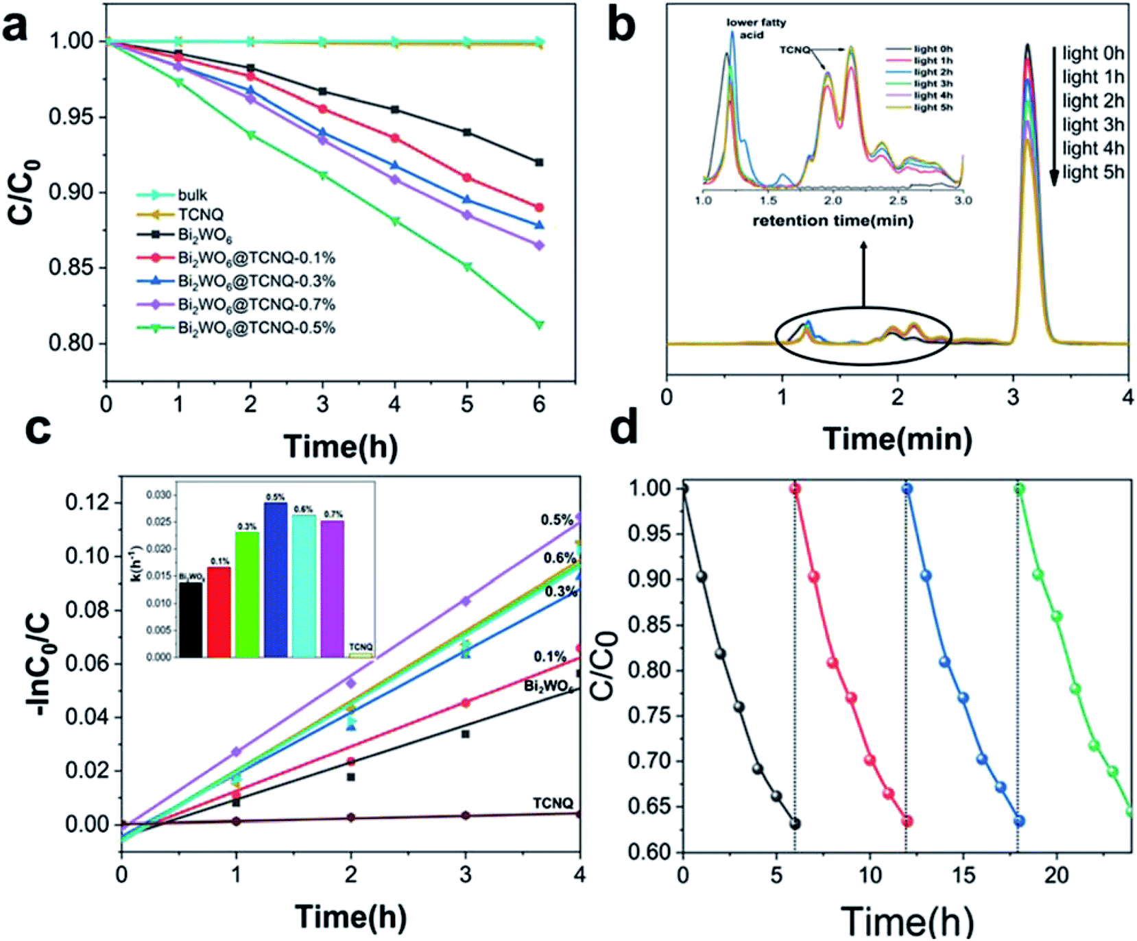 | ||
| Fig. 1 Comparison of different photocatalysts for photodegradation of phenol (a), HPLC map of initial 5 ppm phenol to the map of phenol after 5 h of photocatalytic degradation (b). Apparent rate constants k of Bi2WO6@TCNQ composite photocatalysts for the degradation of 5 ppm phenol with different TCNQ mass ratios under visible light (λ > 420 nm) (c) and cyclic experiments using Bi2WO6@TCNQ-0.5% for phenol (5 ppm) degradation (d). | ||
At the same time, HPLC was utilized to investigate the changes of phenol and its degradation intermediates along with irradiation time. Fig. 1b shows the changes of phenol and its degradation intermediates with visible light irradiation. The peak at 1.1 min was TCNQ, the peaks at 2.0 and 2.2 min were lower fatty acid, the peak at 3.1 min was phenol. As the reaction proceeded, the intensity of phenol decreased with the irradiation time whereas the lower fatty acid peaks increased gradually indicating that phenol degraded into small organic molecules.
The stability of Bi2WO6@TCNQ was tested by repeated cycling experiments. As shown in Fig. 1d, the photocatalyst exhibited excellent stability. The cyclic photodegradation of 5 ppm phenol was carried out 4 times, for a duration of 6 hours each time. After each cycle, we centrifuged the solution to separate out the photocatalyst; however, because of its nanoscale size and excellent dispersibility in water, there was always a large amount of photocatalyst that did not completely settle, resulting in a loss. However, the subsequent four cycles exhibited similar reaction rates, thus confirming the cycling performance and stability of the photocatalyst for application in photodegradation.
The interfacial charge separation efficiency of photogenerated electrons and holes is a crucial factor for photocatalytic activity. Photocurrents of Bi2WO6@TCNQ electrodes were measured to investigate the interfacial charge separation efficiency of photogenerated electrons and holes. It can be seen from Fig. 2a, photocurrents of Bi2WO6@TCNQ increased remarkably and then decreased with increasing proportion of TCNQ. Bi2WO6@TCNQ-0.5% exhibited the highest photocurrent response. The increase of photocurrent indicates that the separation efficiency of the photoinduced electrons and holes was enhanced greatly, which is the reason for the enhanced photocatalytic activity. It also implies that there may be some interaction between Bi2WO6 and TCNQ. The photocurrent responses decreased gradually when the proportion of TCNQ was over 0.5%, which may be associated with the formation of bulk crystals of TCNQ. The higher the content of TCNQ, the smaller the Bi2WO6 and TCNQ interaction, resulting in lower catalyst activity (Fig. 1a). Electrochemical impedance spectroscopy (EIS) was performed and the results are shown in Fig. 2b. A smaller arc radius on the EIS Nyquist plot of Bi2WO6@TCNQ-0.5% under visible light irradiation can be observed, suggesting a more effective separation efficiency of the photoinduced electron–hole pairs and a faster charge transfer. The fluorescence emission of Bi2WO6@TCNQ-0.5% showed a significant reduction (Fig. 3b). This phenomenon reflected the low recombination probability of photogenerated electrons and holes in Bi2WO6@TCNQ-0.5%.
 | ||
| Fig. 2 (a) Photoresponses of Bi2WO6 and Bi2WO6@TCNQ composites electrodes under the irradiation of visible light (>420 nm) [Na2SO4] = 0.1 M. (b) Electrochemical impedance spectroscopy (EIS) Nyquist plot of Bi2WO6 and Bi2WO6@TCNQ composites upon irradiation (λ > 420 nm). (c) Fluorescence spectra of Bi2WO6 and Bi2WO6@TCNQ composites. (d) UV-DRS spectra of pure Bi2WO6, TCNQ and Bi2WO6@TCNQ. | ||
 | ||
| Fig. 3 TEM images of (a) Bi2WO6 and (b) Bi2WO6@TCNQ-0.5%; (c) XRD patterns of Bi2WO6 and Bi2WO6@TCNQ; (d) HRTEM images of Bi2WO6@TCNQ-0.5%. | ||
The UV-vis DRS spectra of Bi2WO6 and different mass ratios of the Bi2WO6@TCNQ photocatalyst are shown in Fig. 2d. As expected, a sharp fundamental absorption edge rises at 477 nm for Bi2WO6, while the absorption edge of Bi2WO6@TCNQ exhibits an apparent gradual redshift with increasing TCNQ loading. The absorption edge of Bi2WO6@TCNQ-0.5% was at about 521 nm, indicating that absorption edge expanded. The band-edge shift is significant because, in this case, electrons can be stimulated under lower-energy irradiation, allowing for fuller use of the spectrum in comparison to UV photocatalysts. And an apparent red shift for Bi2WO6@TCNQ composites appears as compared to Bi2WO6, which may be related to the charge–transfer transition between the CB or VB of Bi2WO6 and TCNQ.32 Meanwhile, less photo-corrosion occurs with decreasing excitation energy.
In other words, the faster the charge transfer, the higher the separation efficiency of photoinduced electron–hole pairs and the lower the recombination probability of photo induced carriers in Bi2WO6@TCNQ-0.5%. This is also the main reason for the high catalytic activity of Bi2WO6@TCNQ-0.5%.
3.2. Core–shell structure of Bi2WO6@TCNQ
The properties of a material are determined by its structure. Transmission electron microscopy (TEM) analysis shows that the nanosized Bi2WO6 crystals display mainly a thin sheet shaped morphology and the border lengths of the thin sheets are less than 100 nanometers (Fig. 3a). It can be seen from Fig. 3b, the morphology of Bi2WO6@TCNQ does not change significantly; with no aggregation phenomenon than that of Bi2WO6, and TCNQ is exfoliated into sheet structures with rolled edges, the resulting morphology of Bi2WO6@TCNQ is likely to be of a core–shell structure.XRD was employed to characterize the crystal phases of Bi2WO6 and Bi2WO6@TCNQ composites. As shown in Fig. 3c, all the samples present the typical XRD diffraction character of the orthorhombic Bi2WO6 phase (JCPDS 39-0256). However, no distinct diffraction peaks attributed to TCNQ can be detected in Bi2WO6@TCNQ composites, which may be due to the low diffraction intensity, its relatively low dosage amount and good exfoliation of TCNQ in the composite. The results suggest that the incorporation of TCNQ in Bi2WO6@TCNQ composites does not lead to the development of a new crystal phase or changes in preferential orientations of Bi2WO6.
The HRTEM image (Fig. 3d) shows clear lattice fringes. The fringes of d = 0.325 nm match that of the (002) crystallographic plane of Bi2WO6. The lattice structure of Bi2WO6 was very orderly and the outer boundary of the as-prepared sample was distinctly different from the Bi2WO6 core. A distinct core–shell structure was formed and the thickness of the TCNQ layer coated on the Bi2WO6@TCNQ-5% sample was approximately 1 nm, corresponding to two TCNQ layers.33,34
In the FT-IR spectrum of TCNQ, the 2207 cm−1 peak was attributable to C![[triple bond, length as m-dash]](https://www.rsc.org/images/entities/char_e002.gif) N stretching vibration modes. The characteristic vibration of TCNQ at 2207 cm−1 nearly disappeared when TCNQ was loaded onto Bi2WO6, which indicates that the CN bond strength weakened, suggesting that there was a covalent bond between TCNQ and Bi2WO6. This interaction is beneficial to the charge migration and the stability of core–shell structure. The characteristic vibration of TCNQ at 2165 cm−1 gradually weakened with increasing TCNQ, which indicates that the bond strength of W–O weakened and Bi2WO6 combined with TCNQ by chemical bonding rather than mechanical mixing.
N stretching vibration modes. The characteristic vibration of TCNQ at 2207 cm−1 nearly disappeared when TCNQ was loaded onto Bi2WO6, which indicates that the CN bond strength weakened, suggesting that there was a covalent bond between TCNQ and Bi2WO6. This interaction is beneficial to the charge migration and the stability of core–shell structure. The characteristic vibration of TCNQ at 2165 cm−1 gradually weakened with increasing TCNQ, which indicates that the bond strength of W–O weakened and Bi2WO6 combined with TCNQ by chemical bonding rather than mechanical mixing.
Fig. 4b shows the Raman spectra of Bi2WO6 and various Bi2WO6@TCNQ photocatalysts. The Raman shifts at 333, 600 and 708 cm−1 arise from the lattice vibrational peaks of TCNQ crystal, corresponding to the Ag (9) mode, Ag (8) mode and Ag (7) mode of TCNQ crystal,34 respectively. The peak at 143 cm−1 was attributable to the lattice vibrational peaks of Bi2WO6 crystal, which move to a lower wavenumber with increasing TCNQ. The red shift of this band indicates that the bond strengths of W–O weakened, suggesting that there is a covalent bond between the conjugated bond of TCNQ and Bi2WO6.35 The interaction is concerned with the charge transfer absorption peaks and the red shift of the absorption sideband shown in Fig. 2d.
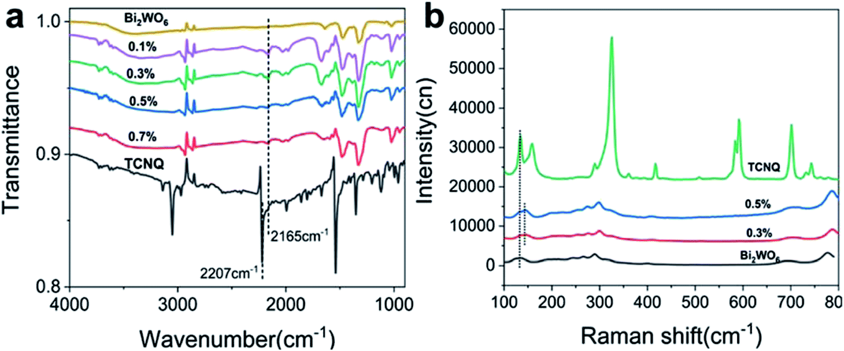 | ||
| Fig. 4 (a) FTIR and (b) Raman spectra of Bi2WO6 and Bi2WO6@ TCNQ photocatalysts. | ||
3.3. Mechanism
To reveal the photocatalytic mechanism, the main oxidative species in the photocatalytic process are detected through the trapping experiments of radicals using tBuOH36 as a hydroxyl radical scavenger, and formic acid37 as holes radical scavenger. As shown in Fig. 5a, the photocatalytic activity of Bi2WO6@TCNQ under visible light irradiation significantly decreases with the addition of a holes scavenger (formic acid) and reduces slightly with the addition of a hydroxyl radical scavenger (tBuOH), indicating that holes radicals are the main oxidative species rather than hydroxyl radicals. On the basis of the above experimental results, a possible mechanism for the degradation of phenol under visible light irradiation is proposed, as shown in Fig. 5b. Photogenerated electrons and holes are generated on the HOMO and LUMO of TCNQ, at the same time they are generated on the VB and CB of Bi2WO6 when irradiated by visible light. As the HOMO orbit of TCNQ is lower than the VB of Bi2WO6.38 photogenerated holes on the HOMO of TCNQ can be injected easily into the VB of Bi2WO6. The holes injected into the VB of Bi2WO6 can directly oxidize the organic pollutant, which contributes to the drastic visible light activity of Bi2WO6@TCNQ photocatalyst in phenol degradation. As the CB position of Bi2WO6 is higher than the lowest unoccupied molecular orbital (LUMO) of TCNQ,38 photogenerated electrons on the CB of Bi2WO6 can be easily injected to the LUMO orbit of TCNQ. However, the LUMO orbit of TCNQ is too low for electrons to easily combine with O2, which prevents the formation of hydroxyl radicals.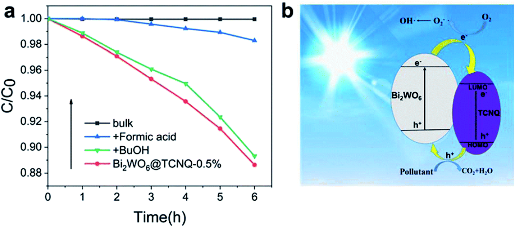 | ||
| Fig. 5 The plots of photogenerated carriers trapping in the system of photodegradation of phenol by (a) Bi2WO6@TCNQ-0.5% under visible light (b) mechanism plots under visible light. | ||
4. Conclusion
Bi2WO6@TCNQ photocatalyst with a core–shell structure was synthesized. This structure enhances the photocatalytic properties of the materials. When the mass ratio of TCNQ reached 0.5%, the apparent rate constant of degradation was nearly 2.2 times that of Bi2WO6. Its visible light activity comes from the injection of photogenerated holes on the HOMO of TCNQ into the VB of Bi2WO6 under visible light irradiation. The holes injected into the VB of Bi2WO6 could directly oxidize the organic pollutant.Conflicts of interest
There are no conflicts to declare.Acknowledgements
This study was partly supported by Chinese National Science Foundation (21621003), Natural Science Foundation of Gansu province (18JR3RA219) and Lanzhou City University key discipline “Analysis and Treatment of Regional Typical Environmental Pollutants”.References
- Y. Li, W. Q. Cui, L. Liu, R. L. Zong, W. Q. Yao, Y. H. Liang and Y. F. Zhu, Removal of Cr(VI) by 3D TiO2-graphene hydrogel via adsorption enriched with photocatalytic reduction, Appl. Catal., B, 2016, 199, 412–423 CrossRef CAS.
- F. Y. Chen, W. J. An, L. Liu, Y. H. Liang and W. Q. Cui, Highly efficient removal of bisphenol A by a three-dimensional graphene hydrogel-AgBr@rGO exhibiting adsorption/photocatalysis synergy, Appl. Catal., B, 2017, 217, 65–80 CrossRef CAS.
- X. Wang, Y. H. Liang, W. J. An, J. S. Hu, Y. F. Zhu and W. Q. Cui, Removal of chromium (VI) by a self-regenerating and metal free g-C3N4/graphene hydrogel system via the synergy of adsorption and photo-catalysis under visible light, Appl. Catal., B, 2017, 219, 53–62 CrossRef CAS.
- L. Liu, L. Ding, Y. G. Liu, W. J. An, S. L. Lin, Y. H. Liang and W. Q. Cui, A stable Ag3PO4@PANI core@shell hybrid: enrichment photocatalytic degradation with π–π conjugation, Appl. Catal., B, 2017, 201, 92–104 CrossRef CAS.
- W. Q. Cui, J. He, H. Wang, J. S. Hu, L. Liu and Y. H. Liang, Polyaniline hybridization promotes photo-electro-catalytic removal of organic contaminants over 3D network structure of rGH-PANI/TiO2 hydrogel, Appl. Catal., B, 2018, 232, 232–245 CrossRef CAS.
- Y. Zhang, W. Q. Cui, W. J. An, L. Liu, Y. H. Liang and Y. F. Zhu, Combination of photoelectrocatalysis and adsorption for removal of bisphenol A over TiO2-graphene hydrogel with 3D network structure, Appl. Catal., B, 2018, 221, 36–46 CrossRef CAS.
- N. Zhang, R. Ciriminna, M. Pagliaro and Y. J. Xu, Nanochemistry-derived Bi2WO6 nanostructures: towards production of sustainable chemicals and fuels induced by visible light, Chem. Soc. Rev., 2014, 43, 5276–5287 RSC.
- Y. G. Zhou, Y. F. Zhang, M. S. Lin, J. L. Long, Z. Z. Zhang, H. X. Lin, J. C. S. Wu and X. X. Wang, Monolayered Bi2WO6 nanosheets mimicking heterojunction interface with open surfaces for photocatalysis, Nat. Commun., 2015, 6, 1–8 CAS.
- L. Tang, J. J. Wang, G. M. Zeng, Y. N. Liu, Y. C. Deng, Y. Y. Zhou, J. Tang, J. J. Wang and Z. Guo, Enhanced photocatalytic degradation of norflox J. J. cin in aqueous Bi2WO6 dispersions containing nonionic surfactant under visible light irradiation, J. Hazard. Mater., 2016, 306, 295–304 CrossRef CAS PubMed.
- X. Y. Kong, Y. Y. Choo, S. P. Chai, A. K. Soh and A. R. Mohamed, Oxygen vacancy induced Bi2WO6 for the realization of photocatalytic CO2 reduction over the full solar spectrum: from the UV to the NIR region, Chem. Commun., 2016, 52, 14242–14245 RSC.
- Y. H. B. Liao, J. X. Wang, J. S. Lin, W. H. Chung, W. Y. Lin and C. C. Chen, Synthesis, photocatalytic activities and degradation mechanism of Bi2WO6 toward crystal violet dye, Catal. Today, 2011, 174, 148–159 CrossRef CAS.
- S. Y. Dong, X. H. Ding, T. Guo, X. P. Yue, X. Han and J. H. Sun, Self-assembled hollow sphere shaped Bi2WO6/RGO composites for efficient sunlight-driven photocatalytic degradation of organic pollutants, Chem. Eng. J., 2017, 316, 778–789 CrossRef CAS.
- L. S. Zhang, W. Z. Wang, L. Zhou and H. L. Xu, Bi2WO6 nano-and microstructures: shape control and associated visible-light-driven photocatalytic activities, Small, 2007, 3, 1618–1625 CrossRef CAS PubMed.
- Z. J. Zhang, W. Z. Wang, L. Wang and S. M. Sun, Enhancement of visible-light photocatalysis by coupling with narrow-band-gap semiconductor: a case study on Bi2S3/Bi2WO6, ACS Appl. Mater. Interfaces, 2012, 4, 593–597 CrossRef CAS PubMed.
- N. Tian, Y. H. Zhang, H. W. Huang, Y. He and Y. X. Guo, Influences of Gd substitution on the crystal structure and visible-light-driven photocatalytic performance of Bi2WO6, J. Phys. Chem. C, 2014, 118, 15640–15648 CrossRef CAS.
- Y. H. Xiang, P. Ju, Y. Wang, Y. Sun, D. Zhang and J. Q. Yu, Chemical etching preparation of the Bi2WO6/BiOI p–n heterojunction with enhanced photocatalytic antifouling activity under visible light irradiation, Chem. Eng. J., 2016, 288, 264–275 CrossRef CAS.
- J. Tian, Y. H. Sang, G. W. Yu, H. D. Jiang, X. N. Mu and H. Liu, A Bi2WO6-based hybrid photocatalyst with broad spectrum photocatalytic properties under UV, visible, and near-infrared irradiation, Adv. Mater., 2013, 25, 5075–5080 CrossRef CAS PubMed.
- G. Tan, J. Huang, L. Zhang, H. Ren and A. Xia, An enhanced visible-light-driven photocatalyst: conduction band control of Bi2WO6 crystallites by Cu ion modification, Ceram. Int., 2014, 40, 11671–11679 CrossRef CAS.
- Q. S. Wu, Y. Cui, L. M. Yang, G. Y. Zhang and D. Z. Gao, Facile in situ photocatalysis of Ag/Bi2WO6 heterostructure with obviously enhanced performance, Sep. Purif. Technol., 2015, 142, 168–175 CrossRef CAS.
- Y. J. Wang, X. J. Bai, C. S. Pan, J. He and Y. F. Zhu, Enhancement of photocatalytic activity of Bi2WO6 hybridized with graphite-like C3N4, J. Mater. Chem., 2012, 22, 11568–11573 RSC.
- i. I. Garcia-Yoldi, J. S. Miller and J. J. Novoa, Theoretical study of the electronic structure of [tetrathiafulvalene]22+ dimers and their Long, intradimer multicenter bonding in solution and the solid state, J. Phys. Chem. A, 2008, 113, 484–492 CrossRef PubMed.
- J. Ferraris, D. O. Cowan, V. Walatka and J. H. Perlstein, Electron Transfer in a New Highly Conducting Donor-Acceptor Complex, J. Am. Chem. Soc., 1973, 95, 948–949 CrossRef CAS.
- Y. Washino, K. Murata, M. Ashizawa, S. Kawauchi and T. Michinobu, Creation of persistent charge-transfer interactions in TCNQ polyester, Polym. J., 2011, 43, 364–369 CrossRef CAS.
- N. Yoshioka, H. Nishide, K. Inagaki, K. Inagaki and E. Tsuchida, Electrical conductive and magnetic properties of conjugated tetrathiolate nickel polymers, Polym. Bull., 1990, 23, 631–636 CrossRef CAS.
- S. Inagi, K. Naka and Y. Chujo, Functional polymers based on electron-donating TTF and derivatives, J. Mater. Chem., 2007, 17, 4122–4135 RSC.
- B. J. Li and H. Q. Cao, ZnO@graphene composite with enhanced performance for the removal of dye from water, J. Mater. Chem., 2011, 21, 3346–3349 RSC.
- T. G. Xu, L. W. Zhang, H. Y. Cheng and Y. F. Zhu, Significantly enhanced photocatalytic performance of ZnO via graphene hybridization and the mechanism study, Appl. Catal., B, 2011, 101, 382–387 CrossRef CAS.
- Y. Yang, L. L. Ren, C. Zhang, S. Huang and T. X. Liu, Facile Fabrication of Functionalized Graphene Sheets (FGS)/ZnO Nanocomposites with Photocatalytic Property, ACS Appl. Mater. Interfaces, 2011, 3, 2779–2785 CrossRef CAS PubMed.
- X. J. Bai, L. Wang, R. L. Zong, Y. H. Lv, Y. Q. Sun and Y. F. Zhu, Performance Enhancement of ZnO Photocatalyst via Synergic Effect of Surface Oxygen Defect and Graphene Hybridization, Langmuir, 2013, 29, 3097–3105 CrossRef CAS PubMed.
- Y. J. Wang, R. Shi, J. Lin and Y. F. Zhu, Enhancement of photocurrent and photocatalytic activity of ZnO hybridized with graphite-like C3N4, Energy Environ. Sci., 2011, 4, 2922–2929 RSC.
- C. Zhang and Y. F. Zhu, Synthesis of square Bi2WO6 nanoplates as high-activity visible-light-driven photocatalysts, Chem. Mater., 2005, 17, 3537–3545 CrossRef CAS.
- J. Yang, X. Wang, X. Zhao, J. Dai and S. Mo, Synthesis of uniform Bi2WO6-reduced graphene oxide nanocomposites with significantly enhanced photocatalytic reduction activity, J. Phys. Chem. C, 2015, 119, 3068–3078 CrossRef CAS.
- R. E. Long, R. A. Sparks and K. N. Trueblood, The crystal and molecular structure of 7,7,8,8-tetracyanoquinodimethane, Acta Crystallogr., 1965, 18, 932–939 CrossRef CAS.
- Z. P. Hu, Z. X. Shen, L. Qin, S. H. Tang, M. H. Kuok, G. Q. Xu, K. F. Mok and H. H. Huang, High pressure Raman studies of 7,7,8,8-tetracyanoquinodimethane (TCNQ) and CuTCNQ, J. Mol. Struct., 1995, 356, 163–168 CrossRef CAS.
- Y. J. Wang, R. Shi, J. Lin and Y. F. Zhu, Significant photocatalytic enhancement in methylene blue degradation of TiO2 photocatalysts via graphene-like carbon in situ hybridization, Appl. Catal., B, 2010, 100, 179–183 CrossRef CAS.
- H. J. Lee and W. Y. Choi, Photocatalytic Oxidation of Arsenite in TiO2 Suspension: Kinetics and Mechanisms, Environ. Sci. Technol., 2002, 36, 3872–3878 CrossRef CAS PubMed.
- T. Tan, D. Beydoun and R. Amal, Effects of organic hole scavengers on the photocatalytic reduction of selenium anions, J. Photochem. Photobiol., A, 2003, 159, 273–280 CrossRef CAS.
- N. Martín, J. L. Segura and C. Seoane, Design and synthesis of TCNQ and DCNQI type electron acceptor molecules as precursors for ‘organic metals’, J. Mater. Chem., 1997, 7, 1661–1676 RSC.
Footnote |
| † Electronic supplementary information (ESI) available. See DOI: 10.1039/c8ra06304d |
| This journal is © The Royal Society of Chemistry 2018 |