 Open Access Article
A facile strategy for modifying boron nitride and enhancing its effect on the thermal conductivity of polypropylene/polystyrene blends†
Xueliang Jiangab,
Pengfei Mab,
Feng You *ab,
Chu Yao
 ab,
Junlong Yaoab and
Fangjun Liuab
aHubei Key Laboratory of Plasma Chemistry and New Materials, China
bSchool of Materials Science and Engineering, Wuhan Institute of Technology, Wuhan 430205, China. E-mail: 490912761@qq.com; youfeng.mse@wit.edu.cn; chuyao@wit.edu.cn
First published on 17th September 2018
Abstract
Boron nitride (BN) possesses excellent thermal conductivity and remarkable insulating properties. However, poor compatibility between BN fillers and a polymer matrix and the weak ultimate mechanical properties of polymer composites are still big challenges to industrial applications in the thermal conductive field. In this paper, the dispersion of BN in a polystyrene (PS) matrix can be improved through the surface modification of BN by introducing in situ dispersion of polystyrene. Subsequently, the selective localization of modified BN in the PS phase can be realized. A co-continuous structure of polymer blends is designed to enhance the thermal conductivity of PS by introducing another polypropylene (PP) phase. The co-continuous PS/PP (60/40, w/w) phases can benefit further enhancement of thermal conductivity of PS due to the selective localization of modified BN in the PS phase. Furthermore, the thermal conductivity of PS/PP blends with only 14.5 wt%-modified BN is 2 times higher than that of neat PP and 30% higher than that of PP/BN.
Introduction
Recently, polymer composites with unique physical and chemical properties have aroused much attention in electronic packaging, machine manufacturing and light-emitting diode (LED) applications.1–3 Thermal conductivity, insulation and flame resistance are inevitable and significant properties for related product performance. Unfortunately, many polymer materials are thermal insulating materials with average thermal conductivity lower than 0.3 W m−1 K−1,4,5 which is discrepant of excellent heat dissipation. Therefore, much effort has been focused on conquering this drawback and to obtain high thermal conductive polymer materials,6,7 for instance, incorporating thermal conductive fillers.The addition of conductive fillers to a polymer matrix is an efficient method to achieve high thermal conductive polymer materials. Generally, several fillers are often utilized such as aluminum nitride,8 graphene,9 silicon carbide,10 carbon nanotubes (CNTs),11 boron nitride,12,13 and carbon black (CB).14 However, the thermal conductivity of polymer composites is still low when these conductive fillers are introduced. The main reasons for this phenomenon are ascribed to the weak interfacial interaction between filler and polymer matrix and the low aspect ratio of fillers.15 Although high loading fillers can increase the thermal conductivity of polymer matrix, the deterioration in flexibility and high cost after increasing the content of thermal conductive filler restrain their potential applications. To date, several strategies have been proposed to enhance the thermal conductivity of polymer composites to control the filler loadings. For example, models of double percolation structure and 3D network structure have been employed.16–18 Depending on the different methods, a 3D network can be constructed using the ice-templating method,19 core–shell segregated structure,20 3D-foam21 and aerogels.22 Boron nitride (BN) is a new two-dimensional inorganic filler that has been incorporated into polymer matrices to fabricate thermal conductive polymer composites. A clear enhancing effect can be obtained due to its high thermal conductivity.23–28 Hu29 et al. have fabricated three-dimensional BN network composites by combining controlled anisotropic freeze-casting with infiltration methods. In addition, inorganic filler coating polymer particle via electrostatic interaction30 and π–π self-assembling31 has also been used through hot-pressing in the temperature region of the glass-transition temperature and melting point to realize the conductive pathway. Alternatively, 3D foams of BN can be obtained by growth on Ni templates by using chemical vapor deposition, followed by etching of Ni.21 This structure has been reported by Pettes,32 and it can decrease the internal contact thermal resistance. Therefore, constructing three-dimensional structures can effectively improve heat transfer and reduce the interfacial thermal resistance between fillers. Meanwhile, more heat transmission channels can be formed through the three-dimensional structure.33 Moreover, two other methods that adopt characteristics found in nature have been employed to enhance the thermal conductivity of polymer matrix, and these are spider dragline silk and natural nacre. The first method reported by Wang demonstrated that thermal conductivity could increase with the enhancement of strain.34 This phenomenon occurs because of good orientation of crystalline regions and strong intrachain and interchain H-bonds. The second way is to construct aligned brick-and-mortar structures, which results in outstanding mechanical strength and high Young's modulus for the final materials. Some attempts have been focused on generating high thermal conductive materials by imitating the structure of natural nacre.35 Moreover, designing a multilayered structure is another way to augment the filler content via controlling its interdiffusion in an immiscible polymer pair.36
Recently, a lot of research has been performed and previously reported on the preparation of thermal conductive polymer composites.37–40 In our present study, a facile preparation of high thermal conductivity composite was reported by constructing a double percolation structure and controlling the distribution of modified BN in the polystyrene (PS) phase. First, PS microsphere-coated BN was fabricated by in situ dispersion polymerization of silanized BN and styrene. Afterward, the modified BN and commercial PS were mixed through a two-roll mill and further processed with PP in a fixed proportion by melt blending. The resultant polymer composites exhibited higher thermal conductivity than PP/BN, where fillers can be constrained to disperse in the PS phase in the double percolation structure.
Experimental
Materials
h-BN platelets (D50 = 50 μm) were purchased from Jonye Ceramic company, Zi Bo, China. 3-Aminopropyltriethoxysilane (KH550) was obtained from Sinopharm Chemical Regent Co. Ltd. Potassium persulfate and polyvinylpyrrolidone were purchased from Shanghai Lingfeng Chemical Reagent Co. Ltd. and Sinopharm Chemical Reagent Co. Ltd. Styrene was supplied by Sinopharm Chemical Regent Co. Ltd. to form the PS microsphere. Polypropylene (PP) and polystyrene (PS) spheres were provided by Sinopec Lanzhou Company and Sinopec Beijing Yanshan Company with melt flow indexes of 2.6 g/10 min and 8.0 g/10 min, respectively.Synthesis of PS-coated BN
The synthesis process of PS-coated BN was divided into two steps. In the first step, BN was modified by 3-aminopropyltriethoxysilane (KH550). To introduce hydroxyl on BN, BN flakes were thermally treated in a muffle furnace at 1000 °C for 2 h under an air atmosphere.41 Afterward, hydroxylated BN (10 g), 1 ml KH550 and 0.2 ml formic acid (adjustment of the solution pH value) were put into a three-necked flask with an existing 100 ml ethanol–water (9![[thin space (1/6-em)]](https://www.rsc.org/images/entities/char_2009.gif) :
:![[thin space (1/6-em)]](https://www.rsc.org/images/entities/char_2009.gif) 1) mixed solution using ultrasonic treatment for 20 min. The mixture solution was then stirred at 35 °C for 24 h to achieve silanization. Afterward, the resultant mixture was washed with ethanol, centrifuged and dried in oven at 50 °C for 8 h. In the second step, 8 g purified styrene and 5.3 g KH550-modified BN (the BN/St feeding ratio was 1
1) mixed solution using ultrasonic treatment for 20 min. The mixture solution was then stirred at 35 °C for 24 h to achieve silanization. Afterward, the resultant mixture was washed with ethanol, centrifuged and dried in oven at 50 °C for 8 h. In the second step, 8 g purified styrene and 5.3 g KH550-modified BN (the BN/St feeding ratio was 1![[thin space (1/6-em)]](https://www.rsc.org/images/entities/char_2009.gif) :
:![[thin space (1/6-em)]](https://www.rsc.org/images/entities/char_2009.gif) 1.5) were poured into 100 ml methyl alcohol; then, 0.15 g K2S2O8 and 0.12 g PVP were added. The mixture was treated in an ultrasound cleaner for 30 min. The in situ polymerization of styrene began at 70 °C for 6 h. Finally, the resultant mixture was washed several times with distilled water and ethanol and dried in an oven at 50 °C for 8 h. The synthesis procedure of PS-modified BN (BN@PS) is depicted in Scheme 1a.
1.5) were poured into 100 ml methyl alcohol; then, 0.15 g K2S2O8 and 0.12 g PVP were added. The mixture was treated in an ultrasound cleaner for 30 min. The in situ polymerization of styrene began at 70 °C for 6 h. Finally, the resultant mixture was washed several times with distilled water and ethanol and dried in an oven at 50 °C for 8 h. The synthesis procedure of PS-modified BN (BN@PS) is depicted in Scheme 1a.
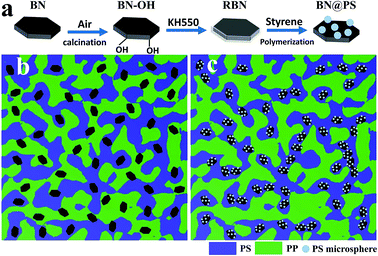 | ||
| Scheme 1 (a) Schematic diagram of the modification of BN (b) and (c) Schematic illustration of the double percolated structure. | ||
Preparation of BN@PS/PS binary composites, BN@PS/(PP/PS) ternary composites and BN/(PP/PS) ternary composites
The prepared BN@PS powder and PS pellets were melt blended to prepare BN@PS/PS binary composites by using a two-roll mixer at 130 °C for 30 min. The weight fractions of BN@PS in BN@PS/PS binary composite were 0, 5 wt%, 10 wt%, 15 wt%, 20 wt%, 30 wt% and 40 wt%. Subsequently, BN@PS/(PP/PS) ternary composites were prepared by melt blending BN@PS/PS binary composites with PP. The weight ratio of PP and PS (including the in situ polymerization PS granules) was fixed at 4![[thin space (1/6-em)]](https://www.rsc.org/images/entities/char_2009.gif) :
:![[thin space (1/6-em)]](https://www.rsc.org/images/entities/char_2009.gif) 6 (Fig. S1†) and the actual content of BN in ternary composites can be calculated by using thermal gravimetric analysis. The detailed compositions are listed in Table 1, and the processing procedures were carried out in a Haake mixer at 175 °C and 50 rpm for 10 min. BN/(PP/PS) ternary composites with different contents of BN were also fabricated by using the same processing conditions for comparison. All composites were then compression molded at 180 °C under 15 MPa to prepare testing samples. The schematic diagram of fabricating BN@PS/(PP/PS) composites and BN/(PP/PS) composites is presented in Scheme 1b and c by contrast.
6 (Fig. S1†) and the actual content of BN in ternary composites can be calculated by using thermal gravimetric analysis. The detailed compositions are listed in Table 1, and the processing procedures were carried out in a Haake mixer at 175 °C and 50 rpm for 10 min. BN/(PP/PS) ternary composites with different contents of BN were also fabricated by using the same processing conditions for comparison. All composites were then compression molded at 180 °C under 15 MPa to prepare testing samples. The schematic diagram of fabricating BN@PS/(PP/PS) composites and BN/(PP/PS) composites is presented in Scheme 1b and c by contrast.
| BN/wt% | PS/wt% | PP/wt% | |
|---|---|---|---|
| BN@PS/(PP/PS) (3.37%) | 3.37 | 58.0 | 38.63 |
| BN@PS/(PP/PS) (6.9%) | 6.9 | 55.9 | 37.2 |
| BN@PS/(PP/PS) (10.6%) | 10.6 | 53.6 | 35.8 |
| BN@PS/(PP/PS) (14.5%) | 14.5 | 51.3 | 34.2 |
Characterization
BN flakes, RBN, and BN@PS were measured with IS50 FT-IR. Thermal gravimetric analysis (TGA) was carried out using a Netzsch STA 409 PC thermogravimetric analyzer under a nitrogen atmosphere. The temperature region was from room temperature to 800 °C with a heating rate of 10 °C min−1. Morphology and microstructure of composites were observed by scanning electron microscopy (SEM, JSM-5510LV). The prepared test specimen was fractured in liquid nitrogen and then sputter-coated. To further analyze the elements in the samples and the relative amount of PS and BN in BN@PS sample, Energy Dispersive Spectrometry (EDS) was performed at an acceleration voltage of 15 eV. In addition, the fractured surfaces of BN@PS/(PP/PS) ternary composites were etched in chloroform solvent before SEM observation to remove the PS phase. Dynamic mechanical analysis (DMA) of composites was carried out by using a DMAQ800 (TA, American) instrument with a heating rate of 5 °C min−1 from 30 °C to 155 °C at 1 Hz. The thermal conductivity of the nanocomposites was measured on a DRL-III-C heat flow meter instrument (Xiangtan Xiangyi Instrument Co. Ltd) according to the standard ASTM D5470.42 Samples were prepared with a diameter of 30 mm and thickness of 2 mm. Each sample was measured three times, and the average value was calculated.Results and discussion
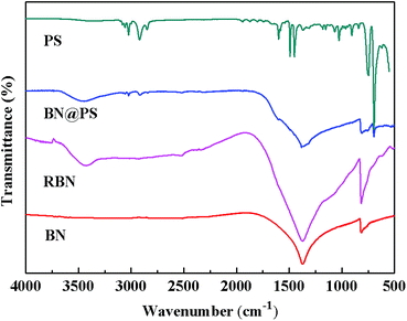
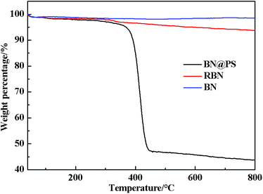
Fig. 1 shows the Fourier transform infrared (FTIR) spectra of BN, RBN, PS and BN@PS samples. Pristine BN exhibits two characteristic absorption peaks at 1369 cm−1 and 817 cm−1, which can be ascribed to the out of plane bending of B–N–B and the B–N in-plane stretching vibration, respectively. After surface modification with KH550, RBN presents two absorption peaks at 985 cm−1 and 1068 cm−1 referred to Si–O bond stretching due to the covalent combination between KH550 and BN. In addition, asymmetric and symmetric stretchings of –CH2– at 2930 cm−1 and 2850 cm−1 can also be demonstrated by the modification of KH550 on BN surfaces. The small absorption peak around 1600 cm−1 corresponds to the vibration of the benzene skeleton, indicating the generation of PS on BN surfaces for BN@PS.The TGA curves of BN, RBN, BN@PS are shown in Fig. 2. It can be seen that BN displays almost no clear weight loss from room temperature to 800 °C because of its high thermal stability. However, a slight mass loss is exhibited for RBN at 100 °C, indicating the decomposition of KH550 on the BN surface. The weight loss around 500 °C might be caused by the pyrolysis of chemically bonded silane molecules. As for BN@PS, two different degradations appear at 150–300 °C and 390–470 °C, respectively. One degradation results from the removal of weak hydroxyl groups and pyrolysis of chemically bonded silane molecules, and the other degradation is due to the thermal decomposition of PS. Approximately 45 wt% of mass loss can be observed through the TGA curve of BN@PS. Therefore, the content of BN in BN@PS is 55 wt% after calculating the experimental data. The actual content of BN in BN@PS/(PP/PS) ternary composites can also be calculated using this measurement.
BN@PS can be synthesized by incorporating modified BN during the polymerization of styrene monomer (Fig. 3a). From Fig. 3b and c, it can be seen that PS microspheres with a uniform particle size (600–800 nm) were prepared by dispersion polymerization of styrene. A uniform particle diameter distribution of PS microsphere was further demonstrated via SEM. Furthermore, good adhesion between PS microspheres with BN platelets can also be observed in Fig. 3c.
To confirm the structure of BN@PS, SEM combined with EDS mapping characterization was conducted for BN@PS powder. EDS mapping analysis was carried out on this region, which is shown as red rectangle in Fig. 4. The blue dots, red dots, and green dots corresponding to the distribution states of N, B and C indicated that the PS microspheres are successfully adsorbed on BN surface in accordance with the SEM results demonstrated in Fig. 3. The EDS analysis for the weight percentage of each element can be carried out. The results were 22.7 wt%, 45.5 wt%, 31.8 wt% corresponding to B, C and N. Therefore, the mass ratio of BN to PS was 1.2![[thin space (1/6-em)]](https://www.rsc.org/images/entities/char_2009.gif) :
:![[thin space (1/6-em)]](https://www.rsc.org/images/entities/char_2009.gif) 1, which is well correlated with the above TGA results.
1, which is well correlated with the above TGA results.
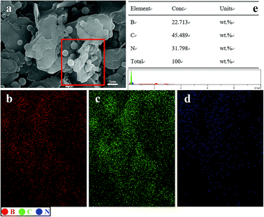 | ||
| Fig. 4 SEM micrographs, element mapping and EDS analysis of BN@PS: (a) SEM, (b) B element, (c) C element, (d) N element, (e) EDS analysis. | ||
The phase morphologies of PS/PP blends are presented in Fig. 5. The effect of different weight ratios of PS and PP on the phase morphology of PS/PP polymer blends was investigated in our laboratory (ESI, S1†). Finally, the weight ratio of PS/PP was fixed at 6![[thin space (1/6-em)]](https://www.rsc.org/images/entities/char_2009.gif) :
:![[thin space (1/6-em)]](https://www.rsc.org/images/entities/char_2009.gif) 4 to achieve the co-continuous structure. It can be clearly seen that a co-continuous structure appeared for this weight ratio of polymer blends. In addition, BN@PS could be found to be selectively localized in the PS phase due to comparative large interfacial interaction between modified BN and PS (Fig. 5b and c). Consequently, the double percolation structure of thermal conductive network was generated, leading to the enhancement of thermal conductivity for PS. In other words, the incorporation of the PP component increased the actual loadings of BN in the PS phase.
4 to achieve the co-continuous structure. It can be clearly seen that a co-continuous structure appeared for this weight ratio of polymer blends. In addition, BN@PS could be found to be selectively localized in the PS phase due to comparative large interfacial interaction between modified BN and PS (Fig. 5b and c). Consequently, the double percolation structure of thermal conductive network was generated, leading to the enhancement of thermal conductivity for PS. In other words, the incorporation of the PP component increased the actual loadings of BN in the PS phase.
 | ||
Fig. 5 SEM images of fractured surfaces for (a) PP/PS (4![[thin space (1/6-em)]](https://www.rsc.org/images/entities/char_2009.gif) : :![[thin space (1/6-em)]](https://www.rsc.org/images/entities/char_2009.gif) 6) and BN@PS/(PP/PS) composites with different contents of BN (b) 3.37 wt%, (c) 14.5 wt%. 6) and BN@PS/(PP/PS) composites with different contents of BN (b) 3.37 wt%, (c) 14.5 wt%. | ||
Dynamic mechanical properties of BN@PS/(PP/PS) composites and BN/(PP/PS) composites are given in Fig. 6 and 7. Fig. 6 shows the storage modulus of temperature with different BN contents. All curves exhibited the same tendency: the storage modulus increases with the increase in BN content. Owing to the high stiffness of the BN fillers, a large stress transferring effect from matrix to filler led to reinforcing effect on the final mechanical properties of composites. The storage modulus of BN@PS/(PP/PS) composites was higher than that of BN/(PP/PS) composites without modified BN. The possible reason is that the interfacial interaction between modified BN and PS phase was higher than that of composites without modified BN. The glass transition temperature (Tg) of PS in different composites can also be found in Fig. 7. Tg of PP/PS blends was 125 °C; it increased with BN content for BN@PS/(PP/PS) composites. When the modified BN was 10.6 wt%, Tg of BN@PS/(PP/PS) composites increased to 129 °C. By contrast, BN without treatment had negligible effect on Tg of BN/(PP/PS) composites due to random dispersion of BN in the PS or PP phase. This difference in Tg further verified the selective localization of BN in the PS phase through in situ polymerization of the styrene monomer, which complied well with the above SEM observation. The selective localization of BN in the PS phase was good for the enhancement of Tg because of large interfacial interaction between the PS chain segment and modified BN as well as the large hindrance of chain segment motion.
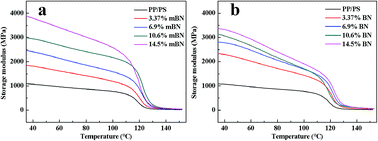 | ||
| Fig. 6 Storage modulus versus temperature of (a) BN@PS/(PP/PS) composites and (b) BN/(PP/PS) composites. | ||
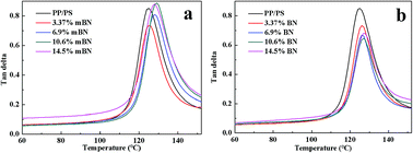 | ||
| Fig. 7 Loss factors versus temperature of (a) BN@PS/(PP/PS) composites and (b) BN/(PP/PS) composites. | ||
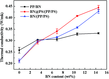
Fig. 8 shows the thermal conductivity of PP/BN, BN/(PP/PS) and BN@PS/(PP/PS) with different contents of BN. It can be seen that the thermal conductivity of these composites increased with BN content. Apparently, the thermal conductivity of PP/BN phase binary composites was inferior to that of BN@PS/(PP/PS) or BN/(PP/PS) ternary composites. Therefore, the double percolation structure of BN in PS/PP with co-continuous structure is essential for enhancing the thermal conductivity of the composites by incorporating low content of thermal conductive filler. Moreover, the thermal conductivity of BN@PS/(PP/PS) composites was higher than that of BN/(PP/PS) composites, indicating that the modification of BN could benefit the enhancement in thermal conductivity. The thermal conductivity of PS/PP blends with only 14.5 wt%-modified BN was 2 times higher than that of neat PP and 30% higher than that of PP/BN. The mechanism of the improvement in thermal conductivity of composites can be explained by the schematic description in Scheme 1. On one hand, modified BN enhanced the interfacial interaction between the fillers and PS matrix and improved the compatibility of fillers, leading to good dispersion of BN in polymer matrix. Simultaneously, the migration of BN to PP phase was inhibited due to large interfacial interaction between modified BN and PS. Therefore, the selective localization of BN resulted in the increase in weight loading for BN in the PS phase. Thus, the actual fraction of BN in the PS phase for BN@PS/(PP/PS) composites was higher than that of BN without treatment in the PS phase for BN/(PP/PS). On the other hand, the thermal interfacial resistance between fillers and matrix is the main reason for low thermal conductivity. Modified BN can reduce the interfacial resistance and enhance the heat dissipation efficiency.43 Therefore, this fabricating method is a facile way to enhance thermal conductivity through the low incorporation of modified BN. High thermal conductivity will be realized in our further study by combining two different dimensional thermal conductive fillers, which will include modified BN.
Conclusions
In this study, BN@PS/(PP/PS) ternary composites with high thermal conductivity were prepared through the double-percolation structural design. The surface modification of BN was successfully conducted by polymerization of styrene on BN. The interfacial interaction between modified BN (PS-coated BN) and the PS phase was enhanced. A double-percolation structure of BN@PS/(PP/PS) ternary composites was obtained through co-continuous PS/PP blends and selective localization of BN in the PS phase. SEM observation and DMA results showed that the selective localization of modified BN in the PS phase was realized. BN@PS/(PP/PS) ternary composites demonstrated higher thermal conductivity than BN/(PP/PS) composites. The fabricating technique of high thermal conductive polymer composites by incorporating BN@PS and combining with a double-percolation structure is a facile method to obtain high thermal conductivity materials with low filler loading.Conflicts of interest
There are no conflicts to declare.Acknowledgements
The financial support from the National Natural Science Foundation of China (No. 51273154), the Hubei Natural Science Foundation (No. 2017CFB289) and Graduate innovation fund of Wuhan Institute of Technology (No. CX2017006) is gratefully acknowledged.References
- S. Liu, B. Zhao, L. Jiang, Y. W. Zhu, X. Z. Fu, R. Sun, J. B. Xu and C. P. Wong, J. Mater. Chem. C, 2017, 6, 257–265 RSC.
- C. Pan, K. Kou, Q. Jia, Y. Zhang, G. Wu and T. Ji, Composites, Part B, 2017, 111, 83–90 CrossRef.
- L. Ren, Q. Li, J. Lu, X. Zeng, R. Sun, J. Wu, J. B. Xu and C. P. Wong, Composites, Part A, 2018, 107, 561–569 CrossRef.
- G. Wang, C. Wang, J. Zhao, G. Wang, C. B. Park and G. Zhao, Nanoscale, 2017, 9, 5996–6009 RSC.
- Y. Yao, X. Zeng, R. Sun, J. B. Xu and C. P. Wong, ACS Appl. Mater. Interfaces, 2016, 8, 15645–15653 CrossRef PubMed.
- Z.-G. Wang, F. Gong, W.-C. Yu, Y.-F. Huang, L. Zhu, J. Lei, J.-Z. Xu and Z.-M. Li, Compos. Sci. Technol., 2018, 162, 7–13 CrossRef.
- C. Yu, J. Zhang, W. Tian, X. Fan and Y. Yao, RSC Adv., 2018, 8, 21948–21967 RSC.
- Q. Wang, C. Bowen, W. Lei, H. Zhang, B. Xie, S. Qiu, M. Y. Li and S. Jiang, J. Mater. Chem. A, 2018, 6, 5040–5051 RSC.
- S. Na, D. Jiao, S. Cui, X. Hou, D. Peng and L. Shi, ACS Appl. Mater. Interfaces, 2017, 9, 2924–2932 CrossRef PubMed.
- D. Shen, Z. Zhan, Z. Liu, C. Yong, Z. Li, Y. Liu, D. Wen, K. Nishimura, C. Li and C. T. Lin, Sci. Rep., 2017, 7, 2606 CrossRef PubMed.
- B. Yin, Y. Wen, H. Jia, J. Wang, Z. Xu and L. Ding, J. Polym. Eng., 2017, 37, 785–794 Search PubMed.
- M. Wang, Z. Jiao, Y. Chen, X. Hou, L. Fu, Y. Wu, S. Li, N. Jiang and J. Yu, Composites, Part A, 2018, 109, 321–329 CrossRef.
- C. Yu, W. Gong, W. Tian, Q. Zhang, Y. Xu, Z. Lin, M. Hu, X. Fan and Y. Yao, Compos. Sci. Technol., 2018, 160, 199–207 CrossRef.
- Y. J. Kim, Y. F. Tan and S. Kim, J. Compos. Mater., 2017, 52, 2047–2053 CrossRef.
- T. M. L. Dang, C. Y. Kim, Y. Zhang, J. F. Yang, T. Masaki and D. H. Yoon, Composites, Part B, 2017, 114, 237–246 CrossRef.
- M. Tanimoto, T. Yamagata, K. Miyata and S. Ando, ACS Appl. Mater. Interfaces, 2013, 5, 4374–4382 CrossRef PubMed.
- S. Uchida, T. Murakami, T. Iwamura, R. Ishige and S. Ando, RSC Adv., 2017, 7, 15492–15499 RSC.
- D.-L. Zhang, J.-W. Zha, C.-Q. Li, W.-K. Li, S.-J. Wang, Y. Wen and Z.-M. Dang, Compos. Sci. Technol., 2017, 144, 36–42 CrossRef.
- X. Zeng, Y. Yao, Z. Gong, F. Wang, R. Sun, J. Xu and C. P. Wong, Small, 2015, 11, 6205–6213 CrossRef PubMed.
- Y. Jiang, Y. Liu, P. Min and G. Sui, Compos. Sci. Technol., 2017, 144, 63–69 CrossRef.
- M. Loeblein, S. H. Tsang, M. Pawlik, E. J. Phua, H. Yong, X. W. Zhang, C. L. Gan and E. H. Teo, ACS Nano, 2017, 11, 2033–2044 CrossRef PubMed.
- H. Huang, P. Chen, X. Zhang, Y. Lu and W. Zhan, Small, 2013, 9, 1397–1404 CrossRef PubMed.
- C. Yu, W. Gong, W. Tian, Q. Zhang, Y. Xu, Z. Lin, M. Hu, X. Fan and Y. Yao, Compos. Sci. Technol., 2018, 160, 199–207 CrossRef.
- X. Yang, Y. Guo, X. Luo, N. Zheng, T. Ma, J. Tan, C. Li, Q. Zhang and J. Gu, Compos. Sci. Technol., 2018, 164, 59–64 CrossRef.
- X. Yang, L. Tang, Y. Guo, C. Liang, Q. Zhang, K. Kou and J. Gu, Composites, Part A, 2017, 101, 237–242 CrossRef.
- Y. Li, G. Xu, Y. Guo, T. Ma, X. Zhong, Q. Zhang and J. Gu, Composites, Part A, 2018, 107, 570–578 CrossRef.
- J. Gu, C. Liang, J. Dang, W. Dong and Q. Zhang, RSC Adv., 2016, 6, 35809–35814 RSC.
- J. Gu, S. Xu, Q. Zhuang, Y. Tang and J. Kong, IEEE Trans. Dielectr. Electr. Insul., 2017, 24, 784–790 Search PubMed.
- J. Hu, Y. Huang, Y. Yao, G. Pan, J. Sun, X. Zeng, R. Sun, J. B. Xu, B. Song and C. P. Wong, ACS Appl. Mater. Interfaces, 2017, 9, 13544–13553 CrossRef PubMed.
- X. Wang and P. Wu, ACS Appl. Mater. Interfaces, 2017, 9, 19934–19944 CrossRef PubMed.
- K. Wu, Y. Li, R. Huang, S. Chai, F. Chen and Q. Fu, Compos. Sci. Technol., 2017, 151, 193–201 CrossRef.
- M. T. Pettes, H. Ji, R. S. Ruoff and L. Shi, Nano Lett., 2012, 12, 2959–2964 CrossRef PubMed.
- X. Li, L. Shao, N. Song, L. Shi and P. Ding, Composites, Part A, 2016, 88, 305–314 CrossRef.
- X. Huang, G. Liu and X. Wang, Adv. Mater., 2012, 24, 1482–1486 CrossRef PubMed.
- G. Pan, Y. Yao, X. Zeng, J. Sun, J. Hu, R. Sun, J. B. Xu and C. P. Wong, ACS Appl. Mater. Interfaces, 2017, 9, 33001–33010 CrossRef PubMed.
- S.-Y. Yang, Y.-F. Huang, J. Lei, L. Zhu and Z.-M. Li, Composites, Part A, 2018, 107, 135–143 CrossRef.
- J. Huang, Y. Zhu, L. Xu, J. Chen, W. Jiang and X. Nie, Compos. Sci. Technol., 2016, 129, 160–165 CrossRef.
- N. Song, D. Jiao, P. Ding, S. Cui, S. Tang and L. Y. Shi, J. Mater. Chem. C, 2015, 4, 305–314 RSC.
- W. Zhou, Y. Gong, L. Tu, L. Xu, W. Zhao, J. Cai, Y. Zhang and A. Zhou, J. Alloys Compd., 2017, 693, 1–8 CrossRef.
- J. Gu, N. Li, L. Tian, Z. Lv and Q. Zhang, RSC Adv., 2015, 5, 36334–36339 RSC.
- Z. Cui, A. J. Oyer, A. J. Glover, H. C. Schniepp and D. H. Adamson, Small, 2014, 10, 2352–2355 CrossRef PubMed.
- X. Yang, C. Liang, T. Ma, Y. Guo, J. Kong, J. Gu, M. Chen and J. Zhu, Adv. Compos. Hybrid Mater., 2018, 1, 207–230 CrossRef.
- Y. Jiang, X. Shi, Y. Feng, S. Li, X. Zhou and X. Xie, Composites, Part A, 2018, 107, 657–664 CrossRef.
Footnote |
| † Electronic supplementary information (ESI) available. See DOI: 10.1039/c8ra06140h |
| This journal is © The Royal Society of Chemistry 2018 |

